Page is loading ...

SAFETY GUIDELINES
ASSEMBLY
OPERATION
MAINTENANCE
TROUBLESHOOTING
REPAIR PARTS
IMPORTANT:
Read the Safety Guidelines
and All Instructions Carefully
Before Operating
Sold by Sears Canada, Inc., Toronto, Ont. M5B 2B8
Model No.
919.727320
Record in the spaces provided.
(1) The Model Number can be found on the
maintenance label on top of the motor
shroud or on the bar code label on the
rear of air tank.
(2) The Date Code Number can be found on
the bar code label on the rear of the air
tank.
(3) The Serial Number can be found on the
bar code label on the rear of the tank.
(4) The Tank Registration Number is located
on the metal data plate which is welded
onto the backside of the air tank. (This
data plate is painted the same color as the
tank.)
Retain these numbers for future reference.
Model No________________________
Serial No________________________
Date Code_______________________
Tank Registration No______________
D20417 Rev. 1 6/28/00
OWNERS MANUAL FOR
CRAFTSMAN
PERMANENTLY LUBRICATED
TANK MOUNTED
AIR COMPRESSOR
CRAFTSMAN

2 — ENG
D20417 Rev. 1 6/28/00
CAUTION indicates a potentially hazardous situation which, if
not avoided, may result in minor or moderate injury.
This manual contains information that is important for you to know and understand. This information relates to protecting
YOUR SAFETY and PREVENTING EQUIPMENT PROBLEMS. To help you recognize this information, we use the symbols
to the right. Please read the manual and pay attention to these sections.
DANGER indicates an imminently hazardous situation which, if
not avoided, will result in death or serious injury.
CAUTION used without the safety alert symbol indicates a
potentially hazardous situation which, if not avoided, may result
in property damage.
WARNING indicates a potentially hazardous situation which, if
not avoided, could result in death of serious injury.
SAFETY GUIDELINES - DEFINITIONS
WARRANTY ......................................................... 2
SAFETY GUIDELINES ......................................... 2
WARNING CHART............................................ 3-5
GENERAL INFORMATION................................... 6
GLOSSARY .......................................................... 6
SPECIFICATION CHART..................................... 7
DESCRIPTION OF OPERATION .......................... 7
TOOLS NEEDED FOR ASSEMBLY ...................... 7
ASSEMBLY .......................................................... 8
BREAK-IN PROCEDURES ................................... 8
Location of Air Compressor ............................ 8
Lubrication and Oil ......................................... 8
Grounding Instructions .................................... 8
Voltage and Circuit Protection ......................... 9
Break-in Procedure ......................................... 9
OPERATING PROCEDURES ....................................... 9
MAINTENANCE ........................................................... 10
Air Filter - Inspection and Replacement .................. 10
Check Valve -Replacement .................................... 10
Safety Valve - Inspection ........................................ 10
Motor ...................................................................... 10
Storage ................................................................... 10
TROUBLESHOOTING GUIDE ................................ 11-12
AIR COMPRESSOR DIAGRAM ................................... 14
PARTS LIST ................................................................. 15
COMPRESSOR PUMP DIAGRAM .............................. 16
PARTS LIST ................................................................. 17
SERVICE NOTES.......................................................... 18
HOW TO ORDER REPAIR PARTS ................ Back Cover
If this air compressor fails due to a defect in material or workmanship within one year from the date
of purchase, RETURN IT TO THE NEAREST SEARS SERVICE CENTER THROUGHOUT CANADA AND
SEARS WILL REPAIR IT, FREE OF CHARGE.
If this air compressor is used for commercial or rental purposes, the warranty will apply for ninety
days (90) from the date of purchase.
This Craftsman Air Compressor warranty gives you specific legal rights and you may have other
rights which vary from province to province.
Sears Canada, Inc., Toronto, Ont. M5B 2B8
FULL ONE YEAR WARRANTY ON AIR COMPRESSORS
TABLE OF CONTENTS

3 — ENG
D20417 Rev. 1 6/28/00
HAZARD
IMPORTANT SAFETY INSTRUCTIONS
RISK OF BURSTING
IT IS NORMAL FOR ELECTRICAL CONTACTS WITHIN THE
MOTOR AND PRESSURE SWITCH TO SPARK.
IF ELECTRICAL SPARKS FROM COMPRESSOR COME INTO
CONTACT WITH FLAMMABLE VAPORS, THEY MAY IGNITE,
CAUSING FIRE OR EXPLOSION.
RESTRICTING ANY OF THE COMPRESSOR VENTILATION
OPENINGS WILL CAUSE SERIOUS OVERHEATING AND
COULD CAUSE FIRE.
UNATTENDED OPERATION OF THIS PRODUCT COULD
RESULT IN PERSONAL INJURY OR PROPERTY DAMAGE.
ALWAYS OPERATE THE COMPRESSOR IN A WELL VENTI-
LATED AREA FREE OF COMBUSTIBLE MATERIALS,
GASOLINE OR SOLVENT VAPORS.
IF SPRAYING FLAMMABLE MATERIALS, LOCATE COMPRES-
SOR AT LEAST 20 FEET AWAY FROM SPRAY AREA. AN
ADDITIONAL LENGTH OF HOSE MAY BE REQUIRED.
STORE FLAMMABLE MATERIALS IN A SECURE LOCATION
AWAY FROM COMPRESSOR.
NEVER PLACE OBJECTS AGAINST OR ON TOP OF COM-
PRESSOR. OPERATE COMPRESSOR IN AN OPEN AREA AT
LEAST 12 INCHES AWAY FROM ANY WALL OR OBSTRUC-
TION THAT WOULD RESTRICT THE FLOW OF FRESH AIR TO
THE VENTILATION OPENINGS.
OPERATE COMPRESSOR IN A CLEAN, DRY, WELL VENTI-
LATED AREA. DO NOT OPERATE UNIT INDOORS OR IN ANY
CONFINED AREA.
ALWAYS REMAIN IN ATTENDANCE WITH THE PRODUCT
WHEN IT IS OPERATING.
SAVE THESE INSTRUCTIONS
IMPROPER OPERATION OR MAINTENANCE OF THIS PRODUCT COULD RESULT IN SERIOUS INJURY AND PROPERTY
DAMAGE. READ AND UNDERSTAND ALL WARNINGS AND OPERATING INSTRUCTIONS BEFORE USING THIS EQUIPMENT.
RISK OF EXPLOSION OR FIRE
AIR TANK: THE FOLLOWING CONDITIONS COULD LEAD TO A WEAKENING OF THE TANK, AND RESULT IN A
VIOLENT TANK EXPLOSION AND COULD CAUSE PROPERTY DAMAGE OR SERIOUS INJURY.
DRAIN TANK DAILY OR AFTER EACH USE. IF TANK DEVEL-
OPS A LEAK, REPLACE IT IMMEDIATELY WITH A NEW TANK OR
REPLACE THE ENTIRE COMPRESSOR.
NEVER DRILL INTO, WELD, OR MAKE ANY MODIFICATIONS
TO THE TANK OR ITS ATTACHMENTS.
THE TANK IS DESIGNED TO WITHSTAND SPECIFIC OPERATING
PRESSURES. NEVER MAKE ADJUSTMENTS OR PARTS
SUBSTITUTIONS TO ALTER THE FACTORY SET OPERATING
PRESSURES.
FOR ESSENTIAL CONTROL OF AIR PRESSURE, YOU MUST
INSTALL A PRESSURE REGULATOR AND PRESSURE GAUGE
TO THE AIR OUTLET OF YOUR COMPRESSOR. FOLLOW THE
EQUIPMENT MANUFACTURERS RECOMMENDATION AND
NEVER EXCEED THE MAXIMUM ALLOWABLE PRESSURE
RATING OF ATTACHMENTS. NEVER USE COMPRESSOR TO
INFLATE SMALL LOW-PRESSURE OBJECTS SUCH AS
CHILDREN’S TOYS, FOOTBALLS, BASKETBALLS. ETC.
1. FAILURE TO PROPERLY DRAIN CONDENSED WATER
FROM THE TANK, CAUSING RUST AND THINNING OF THE
STEEL TANK.
2. MODIFICATIONS OR ATTEMPTED REPAIRS TO THE TANK.
3. UNAUTHORIZED MODIFICATIONS TO THE UNLOADER
VALVE, SAFETY VALVE, OR ANY OTHER COMPONENTS
WHICH CONTROL TANK PRESSURE.
4. EXCESSIVE VIBRATION CAN WEAKEN THE AIR TANK
AND CAUSE RUPTURE OR EXPLOSION.
ATTACHMENTS & ACCESSORIES:
EXCEEDING THE PRESSURE RATING OF AIR TOOLS, SPRAY
GUNS, AIR OPERATED ACCESSORIES, TIRES AND OTHER
INFLATABLES CAN CAUSE THEM TO EXPLODE OR FLY
APART, AND COULD RESULT IN SERIOUS INJURY.
WHAT CAN HAPPEN
HOW TO PREVENT IT
WHAT CAN HAPPEN
HOW TO PREVENT IT

4 — ENG
D20417 Rev. 1 6/28/00
WHAT CAN HAPPEN
HOW TO PREVENT IT
RISK FROM FLYING OBJECTS
THE COMPRESSED AIR STREAM CAN CAUSE SOFT TISSUE
DAMAGE TO EXPOSED SKIN AND CAN PROPEL DIRT, CHIPS,
LOOSE PARTICLES AND SMALL OBJECTS AT HIGH SPEED,
RESULTING IN PROPERTY DAMAGE OR PERSONAL INJURY.
ALWAYS WEAR ANSI Z87.1 APPROVED SAFETY GLASSES
WITH SIDE SHIELDS WHEN USING THE COMPRESSOR.
NEVER POINT ANY NOZZLE OR SPRAYER TOWARD ANY
PART OF THE BODY OR AT OTHER PEOPLE OR ANIMALS.
ALWAYS TURN THE COMPRESSOR OFF AND BLEED PRES-
SURE FROM THE AIR HOSE AND TANK BEFORE ATTEMPTING
MAINTENANCE, ATTACHING TOOLS OR ACCESSORIES.
THE COMPRESSED AIR FROM YOUR COMPRESSOR IS NOT
SAFE FOR BREATHING! THE AIR STREAM MAY CONTAIN
CARBON MONOXIDE, TOXIC VAPORS OR SOLID PARTICLES
FROM THE TANK.
SPRAYED MATERIALS SUCH AS PAINT, PAINT SOLVENTS,
PAINT REMOVER, INSECTICIDES, WEED KILLERS, CONTAIN
HARMFUL VAPORS AND POISONS.
ALWAYS OPERATE AIR COMPRESSOR OUTSIDE IN A CLEAN,
WELL VENTILATED AREA. AVOID ENCLOSED AREAS SUCH AS
GARAGES, BASEMENTS, STORAGE SHEDS, WHICH LACK A
STEADY EXCHANGE OF AIR. KEEP CHILDREN, PETS AND
OTHERS AWAY FROM AREA OF OPERATION.
NEVER INHALE AIR FROM THE COMPRESSOR EITHER
DIRECTLY OR FROM A BREATHING DEVICE CONNECTED TO
THE COMPRESSOR.
WORK IN AN AREA WITH GOOD CROSS-VENTILATION. READ
AND FOLLOW THE SAFETY INSTRUCTIONS PROVIDED ON
THE LABEL OR SAFETY DATA SHEETS FOR THE MATERIAL
YOU ARE SPRAYING. USE A NIOSH/MSHA APPROVED
RESPIRATOR DESIGNED FOR USE WITH YOUR SPECIFIC
APPLICATION.
HAZARD
WHAT CAN HAPPEN
HOW TO PREVENT IT
RISK TO BREATHING
YOUR AIR COMPRESSOR IS POWERED BY ELECTRICITY.
LIKE ANY OTHER ELECTRICALLY POWERED DEVICE, IF IT IS
NOT USED PROPERLY IT MAY CAUSE ELECTRIC SHOCK.
REPAIRS ATTEMPTED BY UNQUALIFIED PERSONNEL CAN
RESULT IN SERIOUS INJURY OR DEATH BY ELECTROCU-
TION.
ELECTRICAL GROUNDING: FAILURE TO PROVIDE ADEQUATE
GROUNDING TO THIS PRODUCT COULD RESULT IN SERIOUS
INJURY OR DEATH FROM ELECTROCUTION. SEE GROUND-
ING INSTRUCTIONS.
NEVER OPERATE THE COMPRESSOR OUTDOORS WHEN IT IS
RAINING OR IN WET CONDITIONS.
NEVER OPERATE COMPRESSOR WITH COVER COMPONENTS
REMOVED OR DAMAGED.
ANY ELECTRICAL WIRING OR REPAIRS REQUIRED ON THIS
PRODUCT SHOULD BE PERFORMED BY AUTHORIZED
SERVICE CENTER PERSONNEL IN ACCORDANCE WITH
NATIONAL AND LOCAL ELECTRICAL CODES.
MAKE CERTAIN THAT THE ELECTRICAL CIRCUIT TO WHICH
THE COMPRESSOR IS CONNECTED PROVIDES PROPER
ELECTRICAL GROUNDING, CORRECT VOLTAGE AND
ADEQUATE FUSE PROTECTION.
WHAT CAN HAPPEN
HOW TO PREVENT IT
RISK OF ELECTRICAL SHOCK

5 — ENG
D20417 Rev. 1 6/28/00
LES PIÈCES MOBILES TELLES QUE LA POULIE, LE VOLANT-MOTEUR ET LA
COURROIE PEUVENT ENTRAÎNER DES BLESSURES GRAVES SI ELLES ENTRENT
EN CONTACT AVEC UNE PARTIE DU CORPS OU DES VÊTEMENTS.
EN TENTANT DE FAIRE FONCTIONNER LE COMPRESSEUR AVEC DES PIÈCES
MANQUANTES OU ENDOMMAGÉES, OU DE RÉPARER LE COMPRESSEUR
SANS LES GARDES DE PROTECTION, ON S’EXPOSE AUX PIÈCES MOBILES,
CE QUI PEUT ENTRAÎNER DES BLESSURES GRAVES.
NE JAMAIS FAIRE FONCTIONNER LE COMPRESSEUR SANS LES GARDES
OU LES COUVERCLES OU LORSQUE CEUX-CI SONT ENDOMMAGÉS.
TOUTE RÉPARATION REQUISE SUR CET APPAREIL DEVRAIT ÊTRE EFFECTUÉE
PAR LE PERSONNEL D’UN CENTRE DE SERVICE APRÈS-VENTE AUTORISÉ.
DANGER
RISQUE RELIÉ AUX PIÈCES MOBILES
RISQUE
PRÉVENTION
LE FAIT DE TOUCHER AUX SURFACES DE MÉTAL EXPOSÉES TELLES QUE LA
TÊTE DU COMPRESSEUR OU LES TUBES DE SORTIE PEUT CAUSER DE GRAVES
BRÛLURES À LA PEAU.
LA TÊTE DU COMPRESSEUR ET LES TUBES DEVIENNENT TRÈS CHAUDS LORS DU
FONCTIONNEMENT.
NE JAMAIS TOUCHER AUX PIÈCES DE MÉTAL EXPOSÉES DU MOTEUR OU
DU COMPRESSEUR DURANT OU IMMÉDIATEMENT APRÈS LE FONCTIONNEMENT.
LE MOTEUR ET LE COMPRESSEUR DEMEURENT CHAUDS PENDANT
PLUSIEURS MINUTES APRÈS LEUR FONCTIONNEMENT.
NE PAS TENTER D’ATTEINDRE LES COMPOSANTES DERRIÈRE LES GARDES DE
PROTECTION ET NE PAS EFFECTUER DE L’ENTRETIEN AVANT D’AVOIR LAISSÉ
REFROIDIR L’APPAREIL.
RISQUE
PRÉVENTION
UN COMPRESSEUR PORTATIF PEUT TOMBER D’UNE TABLE, D’UN ÉTABLI OU
D’UN TOIT. L’IMPACT PEUT CAUSER DES DOMMAGES AU COMPRESSEUR ET
DES BLESSURES CORPORELLES OU LA MORT DE L’UTILISATEUR.
TOUJOURS S’ASSURER DE LA STABILITÉ DU COMPRESSEUR AVANT DE LE
FAIRE FONCTIONNER AFIN DE PRÉVENIR TOUT MOUVEMENT ACCIDENTEL DE
L’APPAREIL. NE JAMAIS UTILISER UN COMPRESSEUR SUR UN TOIT OU
DANS UNE POSITION ÉLEVÉE ; UTILISER PLUTÔT UN BOYAU D’AIR
SUPPLÉMENTAIRE POUR ATTEINDRE LES ENDROITS ÉLEVÉS.
RISQUE
PRÉVENTION
RISQUE DE BRÛLURES
ESW-99 — 9/26/99
RISQUE DE CHUTE
DES FUITES OU DES DÉVERSEMENTS D’HUILE PEUVENT SE PRODUIRE
ET ENTRAÎNER DES RISQUES D’INCENDIE, OU DES PROBLÈMES AUX
VOIES RESPIRATOIRES, DES BLESSURES GRAVES OU LA MORT. DES
FUITES D’HUILE ENDOMMAGENT LES TAPIS, LA PEINTURE ET TOUTE
AUTRE SURFACE DES VÉHICULES OU DES REMORQUES.
RISQUE
PRÉVENTION
TOUJOURS PLACER LE COMPRESSEUR SUR UN TAPIS DE PROTECTION
POUR ÉVITER L’ENDOMMAGEMENT DU VÉHICULE PAR DES FUITES.
RETIRER LE COMPRESSEUR DU VÉHICULE IMMÉDIATEMENT À
L’ARRIVÉE.
RISQUE DE DOMMAGES À LA PROPRIÉTÉ PENDANT LE
TRANSPORT DU COMPRESSEUR
(incendie, inhalation, dommages aux surfaces du véhicule)

6 — ENG
D20417 Rev. 1 6/28/00
An inline air filter which removes moisture and dirt from
compressed air should be used where applicable.
An inline regulator can be used if a more precise
adjustment of air pressure is needed downstream.
CFM: Cubic Feet per Minute.
SCFM: Standard Cubic Feet per Minute; a unit of mea-
sure of air delivery.
PSI: Pounds per Square Inch; a unit of measure of pres-
sure.
ASME: American Society of Mechanical Engineers; made,
tested, inspected and registered to meet the standards
of the ASME.
Cut-In Pressure: While the motor is off, air tank pres-
sure drops as you continue to use your accessory. When
the tank pressure drops to a certain low level and the
pressure switch lever is in "Auto", the motor will restart
automatically. The low pressure at which the motor auto-
matically restarts is called “cut-in pressure.”
You have purchased an air compressor unit consisting
of a one cylinder, single-stage air compressor pump
and air tank. Included are wheels, regulator, gauges,
and handle.
This air compressor requires no oil. Now you can enjoy
all the benefits of having an air compressor without
ever having to purchase, add or change oil.
Your air compressor can be used for operating paint
spray guns, air tools, blow guns, nailers/staplers, air
brushes, and inflator kits. An air pressure regulator is
required for most of the applications.
Cut-Out Pressure: When you turn on your air compres-
sor and it begins to run, air pressure in the air tank be-
gins to build. It builds to a certain high pressure before
the motor automatically shuts off - protecting your air tank
from pressure higher than its capacity. The high pres-
sure at which the motor shuts off is called “cut-out pres-
sure.”
CSA: Electrical products sold in Canada are required to
be certified to the applicable CSA standard (s). Canadian
Standards Association (CSA) is a standards writing and
safety testing organization. Products that are CSA certi-
fied have been evaluated and tested and found to meet
or exceed the applicable CSA standard (s) for safety and
electrical performance.
GENERAL INFORMATION
GLOSSARY
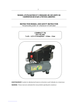
SPECIFICATION CHART
Model No.
Bore
Stroke
Voltage - Single Phase
Minimum Branch Circuit Requirement
Fuse Type
Amperage at Maximum Pressure
Air Tank
/
Capacity
Approximate Cut-in Pressure
Approximate Cut-out Pressure
SCFM @ 40 psi
SCFM @ 90 psi
919.727320
2 3/8"
1.35"
120
15 amps
Time Delay
15.0
ASME
/
25 gal. (U.S.)
100
130
7.8
5.5

7 — ENG
D20417 Rev. 1 6/28/00
Air Compressor Pump: To compress air, the piston
moves up and down in the cylinder. On the downstroke,
air is drawn in through the air intake valves. The exhaust
valves remain closed. On the upstroke of the piston, air
is compressed. The intake valves close and compressed
air is forced out through the exhaust valves, through the
outlet tube, through the check valve and into the air tank.
Check Valve: When the air compressor is operating, the
check valve is “open”, allowing compressed air to enter
the air tank. When the air compressor reaches “cut-out”
pressure, the check valve “closes”, allowing air pres-
sure to remain inside the air tank.
Pressure Switch: The pressure switch is fitted with a
small lever. It is labeled "Auto/O" for automatic run or
off. In the "O" position, the motor will not run. In the "Auto"
position, it automatically starts the motor when the air
tank pressure drops below the factory set “cut-in” pres-
sure. It stops the motor when the air tank pressure reaches
the factory set “cut-out” pressure.
Pressure Release Valve: The pressure release valve lo-
cated on the side of the pressure switch is designed to
automatically release compressed air trapped within the
compressor head and outlet tube. This short release of
air will occur when the air compressor reaches "cut-out"
pressure or the unit is shut off. If the air is not released,
the motor will not be able to start when next required.
Flow Valve: The flow valve allows air to flow from the
head as the motor is getting “up to speed”. Once the
motor reaches normal operating speed, the flow valve
closes and the pump begins to compress air, thus re-
quiring less amp draw on initial start.
Safety Valve: If the pressure switch does not shut off the
air compressor at its cut-out pressure setting, the safety
valve will protect the tank against high pressure by “pop-
ping out” at its factory set pressure (slightly higher than
the pressure switch cut-out setting).
DESCRIPTION OF OPERATION
TOOLS NEEDED FOR ASSEMBLY
Regulator: The air pressure coming from the air tank is
controlled by the regulator. The regulator control knob is
a vibration proof design. Lift the regulator knob to en-
gage and depress the knob to lock. Turn the regulator
knob clockwise to increase pressure and counter-clock-
wise to decrease pressure. To avoid minor readjustment
after making a change in pressure setting, always ap-
proach the desired pressure from a lower pressure. When
reducing from a higher to a lower setting, first reduce to
some pressure less than that desired, then bring up to
the desired pressure. Depending on the air requirements
of each particular accessory, the outlet regulated air pres-
sure may have to be adjusted while operating the acces-
sory.
Regulator Gauge: The outlet pressure gauge indicates
the air pressure available at the outlet side of the regula-
tor. This pressure is controlled by the regulator and is
always less than or equal to the tank pressure. See “Op-
erating Procedures”.
Tank Pressure Gauge: The tank pressure gauge indi-
cates the reserve air pressure in the tank.
Cooling System: This compressor contains an advanced
design cooling system. At the heart of this cooling sys-
tem is an engineered fan. It is perfectly normal for this
fan to blow air through the vent holes in large amounts.
You know that the cooling system is working when air is
being expelled.
Drain Valve: This valve is located at the bottom of the
tank. To drain accumulated moisture from the tank, pull
on the safety valve until tank pressure is 15 PSI. Un-
screw the drain valve and allow the water to drain.
• a 9/16" socket and an open end wrench for attaching
the wheels
• a 3/8" open end wrench or socket to tighten handle
screws

8 — ENG
D20417 Rev. 1 6/28/00
Location of the Air Compressor
Locate the air compressor in a clean, dry and well venti-
lated area. The air filter must be kept clear of obstruc-
tions which could reduce air delivery of the air compres-
sor. The air compressor should be located at least 12"
away from the wall or other obstructions that will interfere
with the flow of fresh intake and cooling air.
Lubrication and Oil
This unit needs no lubrication or oiling.
Grounding Instructions
RISK OF ELECTRICAL SHOCK. In the event of a
short circuit, grounding reduces the risk of shock
by providing an escape wire for the electric
current. This air compressor must be properly
grounded.
This portable air compressor is equipped with a cord hav-
ing a grounding wire with an appropriate grounding plug.
The plug must be used with an outlet that has been in-
stalled and grounded in accordance with all local codes
and ordinances. The outlet must have the same configu-
ration as the plug. DO NOT USE AN ADAPTER.
Inspect the plug and cord before each use. Do not use if
there are signs of damage.
IMPROPER GROUNDING CAN RESULT IN
ELECTRICAL SHOCK.
Do not modify the plug that has been provided. If it
does not fit the available outlet, the correct outlet
should be installed by a qualified technician.
1. Attach the handle to the compressor saddle by
inserting the handle
inside
the compressor saddle
and lining up the two bolt holes on each side. Install
the four screws, two on each side. Tighten securely.
2. Install one shoulder bolt and one nut for each wheel.
Tighten securely. The compressor will sit level if the
wheels are properly installed.
3. Clean and dry underside of air tank leg opposite
wheels. Remove the protective paper strip from the
adhesive backed rubber foot strip. Attach the rubber
foot strip to the bottom of leg. Press firmly into place.
ASSEMBLY
Installing Wheels, Handles, Rubber Foot
Strip
THE WHEELS AND HANDLE DO NOT PROVIDE
ADEQUATE CLEARANCE, STABILITY OR SUP-
PORT FOR PULLING THE UNIT UP AND DOWN
STAIRS OR STEPS. THE UNIT MUST
BE LIFTED, OR PUSHED UP A RAMP.
BREAK-IN PROCEDURES
If repairing or replacing cord or plug, the grounding wire
must be kept separate from the current-carrying wires.
Never connect the grounding wire to a flat blade plug
terminal. The grounding wire has insulation with an outer
surface that is green with or without yellow stripes.
If these grounding instructions are not completely under-
stood, or if in doubt as to whether the compressor is
properly grounded, have the installation checked by a
qualified electrician.
Voltage and Circuit Protection
Refer to page 5 (Specification Chart) for the voltage and
circuit protection requirements of your compressor. Use
only a fuse or circuit breaker that is the same rating as
the branch circuit the air compressor is operated on. If
the compressor is connected to a circuit protected by
fuses, use only dual element time delay fuses.
Refer to Parts List Manual for your compressor. Certain
air compressor models can be operated on a 15 amp
circuit if:
1. Voltage supply to circuit is normal.

9 — ENG
D20417 Rev. 1 6/28/00
This procedure is required only once, before the air com-
pressor is put into service.
1. Set the pressure switch "AUTO/O" lever in the
"O" position for "Off".
2. Plug the power cord into the correct branch circuit
receptacle.
3. Do not attach hose to outlet. Leave the outlet open
to the atmosphere.
4. Turn the regulator
clockwise
, opening it fully, to
prevent air pressure build-up in the tank.
5. Move the "AUTO/O" lever to "AUTO". The com-
pressor will start.
6. RUN THE COMPRESSOR FOR 15 MINUTES.
Make sure the regulator is open and there is no tank
pressure build-up.
7. After 15 minutes, close the regulator by turning it
counterclockwise
. The air tank will fill to cut-out
pressure and then the motor will stop.
2. Circuit is not used to supply any other electrical needs
(lights, appliances, etc.)
3. Extension cords comply with a 15 amp circuit breaker
or 15 amp time delay fuse.
4. Circuit is equipped with a 15 amp circuit breaker or
15 amp time delay fuse.
If any of the above conditions cannot be met, or if opera-
tion of the compressor repeatedly causes interruption of
power, it may be necessary to operate it from a 20 amp
circuit. It is not necessary to change the cord set.
Extension Cords
It is preferable to use extra air hose instead of an exten-
sion cord to avoid voltage drop and power loss to the
motor, and to prevent overheating.
If an extension cord must be used, be sure it is:
• 12 gauge (AWG) or heavier. (Wire size increases as
gauge number decreases. 10 AWG and 8 AWG
may also be used. DO NOT USE 14 OR 16 AWG.)
• a three-wire extension cord that has a three-connec
tor grounding plug, and a three-slot receptacle that
will accept the plug.
• no longer than 50 feet
• in good condition
Break-in Procedure
Serious damage may result if the following
break-in instructions are not closely fol-
lowed.
OPERATING PROCEDURES
6. Always operate the air compressor in well-
ventilated areas; free of gasoline or other solvent
vapors. Do not operate the compressor near the
spray area.
WHEN YOU ARE FINISHED:
7. Set the “AUTO/O” lever to “O”.
8. Turn the regulator
counterclockwise
and set the
outlet pressure to zero.
9. Remove the air tool or accessory.
10. Open the regulator and allow the air to slowly
bleed from the tank. Close the regulator when
tank pressure is approximately 20 psi.
11. Drain water from air tank.
WATER WILL CONDENSE IN THE AIR TANK. IF
NOT DRAINED, WATER WILL CORRODE AND
WEAKEN THE AIR TANK CAUSING A RISK OF
AIR TANK RUPTURE.
NOTE:
If drain cock valve is plugged, release all air
pressure. The valve can then be removed,
cleaned, then reinstalled.
12. After the water has been drained, close the drain
valve. The air compressor can now be stored.
1. Before attaching air hose or accessories, make
sure the "AUTO/O" lever is set to “O” and the air
regulator is closed.
2. Attach hose and accessories.
TOO MUCH AIR PRESSURE CREATES A
HAZARDOUS RISK OF BURSTING. CARE-FULLY
FOLLOW STEPS 3 AND 5 BELOW EACH TIME
THE COMPRESSOR IS USED.
Compressed air from the outfit may contain water
condensation. Do not spray unfiltered air at an
item that could be damaged. Some air operated
tools or devices may require filtered air. Read the
instructions for the air tool or device.
3. Check the manufacturer’s maximum pressure rating
for air tools and accessories. The regulator outlet
pressure must never exceed the maximum
pressure rating.
4. Turn the "AUTO/O" lever to “AUTO” and allow tank
pressure to build. Motor will stop when tank
pressure reaches “cut-out” pressure.
5. Open the regulator by turning it clockwise. Adjust
the regulator to the correct pressure setting. Your
compressor is ready for use.

10 — ENG
D20417 Rev. 1 6/28/00
Keep the air filter clean at all times. Do not operate the com-
pressor with the air filter removed.
A dirty air filter will not allow the compressor to operate at full
capacity. Before you use the compressor, check the air filter to
be sure it is clean.
Check Valve Cleaning - Replacement
Risk of personal injury. Manifold assembly con-
tains compressed air which can be hazardous.
Manifold gets hot during operation.
Before servicing:
• Unplug or disconnect electrical supply to
compressor.
• Bleed tank of pressure.
• Allow compressor to cool.
1. Release all air pressure from air tank and unplug outfit.
2. Remove shroud. (Key Nos. 1 and 2)
3. Loosen the top and bottom nuts and remove the outlet
tube. (Key Nos. 31, 33, and 34)
4. Remove the pressure release tube, fitting, and
connector. (Key Nos. 25, 26 and 27)
5. Unscrew the check valve (turn counterclockwise) using
a socket wrench. (Key No. 17)
6. Check that the valve disc moves freely inside the check
valve and that the spring holds the disc in the upper,
closed position. The check valve may be cleaned with a
solvent, such as paint and varnish remover.
7. Apply a Teflon based pipe sealant to the check valve
threads. Reinstall the check valve (turn clockwise).
8. Replace the pressure release tube and fitting.
9. Replace the outlet tube and tighten top and bottom
nuts.
10. Replace the shroud.
ALL MAINTENANCE AND REPAIR OPERATIONS NOT LISTED MUST BE DONE BY A QUALIFIED SERVICE TECHNICIAN.
UNIT CYCLES AUTOMATICALLY WHEN POWER IS ON. WHEN DOING MAINTENANCE, YOU MAY BE EXPOSED TO
VOLTAGE SOURCES, COMPRESSED AIR OR MOVING PARTS. PERSONAL INJURIES CAN OCCUR. BEFORE
PERFORMING ANY MAINTENANCE OR REPAIR, UNPLUG THE COMPRESSOR AND BLEED OFF ALL AIR PRES-
SURE.
MAINTENANCE
Air Filter - Inspection and Replacement
Hot surfaces. Risk of burn. Compressor heads
are exposed when filter cover is removed. Allow
compressor to cool prior to servicing.
Filter
Filter Retainer
Safety Valve - Inspection
If the safety valve does not work properly,
over-pressurization may occur, causing air tank
rupture or an explosion. Before starting compres-
sor, pull the ring on the safety valve to make sure
that the safety valve operates freely. If the valve is
stuck or does not operate smoothly, it must be
replaced with the same type of valve.
Motor
The motor has an automatic reset thermal overload protector. If
the motor overheats for any reason, the overload protector will
shut off the motor. The motor must be allowed to cool down
before restarting. The compressor will automatically restart
after the motor cools.
If the overload protector shuts the motor off frequently, check
for a possible voltage problem. Low voltage can also be sus-
pected when:
1. The motor does not get up to full power or speed.
2. Fuses blow out when starting the motor; lights dim
and remain dim when motor is started and is running.
Storage
Before you store the air compressor, make sure you do the
following:
1. Review the Maintenance and “Operating Procedures”
sections and perform maintenance as necessary. Be
sure to drain water from the air tank.
2. Protect the electrical cord and air hose from damage
(such as being stepped on or run over). Wind them
loosely around the compressor handle.
Store the air compressor in a clean and dry location.

11 — ENG
D20417 Rev. 1 6/28/00
PROBLEM
CAUSE
Excessive tank pressure - safety
valve pops off.
Air leaks at fittings or hose.
Air leaks at pressure switch
release valve.
Air leaks in air tank or at air tank
welds.
Air leaks between head and valve
plate.
Pressure reading on the regu-
lated pressure gauge drops when
an accessory is used.
Air leak from safety valve.
Knocking noise
Move the pressure switch lever to the “O”
position. If the compressor doesn’t shut off,
disconnect from the electrical outlet source
and return to a Sears Service Center to re-
place the pressure switch.
Return the compressor to Sears Service Center
to check and adjust, or replace switch.
Tighten fittings using teflon tape where air
can be heard escaping. Check fittings with
soapy water solution. DO NOT OVER-
TIGHTEN.
Return to Sears Service Center for replace-
ment of pressure switch.
Check to see if the pin in the bottom of the
pressure release valve is stuck. If it does not
move freely, return to the Service Center for
replacement of pressure switch.
A defective check valve results in a constant
air leak at the pressure release valve when
there is pressure in the tank and the com-
pressor is shut off. Remove and clean or re-
place check valve. DO NOT OVERTIGHTEN.
Air tank must be replaced. Do not repair the
leak. Return compressor to Sears Service
Center.
Torque head screws to 7-10 ft. lbs. If this
does not stop leak, replace seal.
If there is an excessive amount of pressure
drop when the accessory is used, adjust the
regulator.
NOTE
Adjust the regulated pressure under flow con-
ditions (while accessory is being used).
Operate safety valve manually by pulling on
ring. If valve still leaks, it should be
replaced .
Remove and clean, or replace.
CORRECTION
Pressure switch does not shut off
motor when compressor reaches
cut-out pressure.
Pressure switch cut-out too high.
Tube or hose fittings are not tight
enough.
Defective pressure switch release valve.
Defective or dirty check valve.
Defective air tank.
Leaking seal.
It is normal for some pressure drop
to occur.
Possible defect in safety valve.
Defective check valve.
DO NOT DRILL INTO, WELD OR OTHER-
WISE MODIFY AIR TANK OR IT WILL
WEAKEN. THE TANK CAN RUPTURE OR
EXPLODE.
PERFORMING REPAIRS MAY EXPOSE VOLTAGE SOURCES, MOVING PARTS OR COMPRESSED AIR SOURCES.
PERSONAL INJURY MAY OCCUR. PRIOR TO ATTEMPTING ANY REPAIRS, UNPLUG THE COMPRESSOR AND
BLEED OFF TANK AIR PRESSURE.
TROUBLESHOOTING GUIDE

12 — ENG
D20417 Rev. 1 6/28/00
CORRECTION
Compressor is not supply-
ing enough air to operate
accessories.
Compressor is not large enough
for air requirement.
Possible defective motor or
capactior.
Check valve stuck open, putting
pressure on head.
Pressure release valve on pressure
switch has not unloaded head
pressure.
Paint spray on internal motor
parts.
Broken exhaust valve.
Dirty or damaged regulator
internal parts.
Regulator knob continuous
air leak. Regulator will not
shut off at air outlet.
Fuse blown, circuit breaker tripped.
Let motor cool off and overload switch will
auto- matically reset.
1. Check fuse box for blown fuse and replace, if
necessary. Reset circuit breaker. Do not use a
fuse or circuit breaker with higher rating than
that specified for your particular branch circuit.
2. Check for proper fuse; only Time Delay fuses
are acceptable.
3. Check for low voltage conditions and/or
proper extension cord.
4. Disconnect the other electrical appliances
from circuit or operate the compressor on its
own branch circuit.
5. Check for loose electrical connections.
Return to Sears Service Center for inspection or
replacement, if necessary.
Bleed the line by pushing the lever on the pressure
switch to the "O" position; if the valve does not
open, replace it.
Inspect and replace if necessary.
Replace regulator.
Remove and clean, or replace the check valve.
Have compressor checked at Sears Service Center.
Do not operate the compressor in the paint spray
area. See flammable vapor warning.
Clean or replace air intake filter. Do not operate
the air compressor in any paint spray or drywall
sanding area.
Restricted air intake filter.
Check and replace if required.Hole in hose.
Check valve restricted.
Tighten fittings.
Motor will not run or restart. Present tank pressure exceeds
pressure switch "cut-in" pressure.
Motor will start automatically when tank pressure
drops below "cut-in" pressure of pressure switch.
Remove and clean, or replace.
Air leaks.
Motor overload protection switch
has tripped.
CAUSEPROBLEM
Check the accessory air requirement. If it is higher
than the SCFM or pressure supplied by your air
compressor, you need a larger compressor.

CRAFTSMAN
OWNERS MANUAL FOR
PERMANENTLY LUBRICATED
TANK MOUNTED
AIR COMPRESSOR
Sold By Sears Canada, Inc., Toronto, Ont. M5B 2B8
MODEL NO.
The model number of your Sears Air Compressor can be
found
on the maintenance label on the top of the shroud or on the
bar code label on the rear of the air tank.
HOW TO ORDER
REPAIR PARTS
WHEN ORDERING REPAIR PARTS, ALWAYS GIVE THE
FOLLOWING INFORMATION:
• PART NUMBER • PART DESCRIPTION
• MODEL NUMBER • NAME OF ITEM
All parts listed may be ordered from any Sears Service Center
and most Sears stores.
If the parts you need are not stocked locally, your order will be
electronically transmitted to a Sears Repair Parts Distribution
Center for handling.
SERVICE
SERVICE AND REPAIR PARTS
CALL 1-800-665-4455*
Keep this number handy should you require a service call or
need to order repair parts.
If ordering parts make sure you have the name, make and
model no. of the merchandise and the name and number of
the part you wish to order.
*If calling locally, please use one of the following num-
bers:
Regina - 566-5124 Montreal - 333-5740
Toronto - 744-4900 Halifax - 454-2444
Kitchener - 894-7590 Ottawa - 738-4440
Vancouver - 420-8211

4 — FR
D20417 Rev. 1 6/28/00
RISQUE
PRÉVENTION
RISQUE DE PROJECTION D’OBJETS
LE JET D’AIR COMPRIMÉ PEUT CAUSER DES LÉSIONS AUX TISSUS DE
LA PEAU EXPOSÉE ET PEUT PROJETER DE LA SALETÉ, DES COPEAUX, DES
PARTICULES LIBRES ET DE PETITS OBJETS À HAUTE VITESSE, CE QUI
RISQUE DE CAUSER DES DOMMAGES À LA PROPRIÉTÉ OU DES BLESSURES.
PORTER TOUJOURS DES LUNETTES DE PROTECTION HOMOLOGUÉES
ANSI Z87.1 AVEC DES ÉCRANS LATÉRAUX LORS DE L’UTILISATION DU
COMPRESSEUR.
NE JAMAIS DIRIGER LA BUSE OU LE PULVÉRISATEUR VERS SOI, VERS
D’AUTRES PERSONNES OU VERS DES ANIMAUX.
TOUJOURS METTRE LE COMPRESSEUR HORS FONCTION ET PURGER LA
PRESSION DU BOYAU D’AIR ET DU RÉSERVOIR AVANT D’ENTAMER
L’ENTRETIEN OU D’ATTACHER DES OUTILS OU ACCESSOIRES.
L’AIR COMPRIMÉ DE VOTRE COMPRESSEUR D’AIR N’EST PAS SÉCURITAIRE
POUR L’INHALATION. LE JET D’AIR PEUT CONTENIR DU MONOXYDE DE
CARBONE, DES VAPEURS TOXIQUES OU DES PARTICULES SOLIDES DU
RÉSERVOIR.
LES MATIÈRES VAPORISÉES TELLES QUE LA PEINTURE, LES SOLVANTS DE
PEINTURE, LES DÉCAPANTS, LES INSECTICIDES ET LES HERBICIDES
CONTIENNENT DES VAPEURS NOCIVES ET TOXIQUES.
TOUJOURS UTILISER LE COMPRESSEUR D’AIR À L’EXTÉRIEUR, DANS UN
ENDROIT PROPRE ET BIEN AÉRÉ. ÉVITER DES ENDROITS CLOS TELS QUE
GARAGES, SOUS-SOLS ET HANGARS D’ENTREPOSAGE QUI NE SONT PAS
DOTÉS DE SYSTÈMES D’ÉCHANGE D’AIR. GARDER LES ENFANTS, LES
ANIMAUX DOMESTIQUES ET AUTRES, LOIN DE LA ZONE DE TRAVAIL.
NE JAMAIS INHALER L’AIR ÉMIS PAR LE COMPRESSEUR, QUE CE SOIT
DIRECTEMENT OU AU MOYEN D’UN DISPOSITIF RESPIRATEUR BRANCHÉ AU
COMPRESSEUR.
TRAVAILLER DANS UN ENDROIT OÙ IL Y A UNE BONNE VENTILATION
TRANSVERSALE. BIEN LIRE ET RESPECTER LES DIRECTIVES DE SÉCURITÉ
INDIQUÉES SUR L’ÉTIQUETTE OU LA FICHE SIGNALÉTIQUE DE LA MATIÈRE
QUI EST VAPORISÉE. PORTER UN RESPIRATEUR HOMOLOGUÉ PAR LE
NIOSH/MSHA ET CONÇU POUR L’APPLICATION EN QUESTION.
DANGER
RISQUE
PRÉVENTION
RISQUE PAR INHALATION
VOTRE COMPRESSEUR D’AIR EST ALIMENTÉ PAR ÉLECTRICITÉ. COMME
AVEC TOUS LES APPAREILS ÉLECTRIQUES, SI L’APPAREIL N’EST PAS
UTILISÉ DE FAÇON APPROPRIÉE, IL PEUT CAUSER DES CHOCS
ÉLECTRIQUES.
TOUTE RÉPARATION EFFECTUÉE PAR UNE PERSONNE NON QUALIFIÉE
PEUT ENTRAÎNER DES BLESSURES GRAVES OU LA MORT PAR
ÉLECTROCUTION.
MISE À LA TERRE : LE DÉFAUT D’ÉTABLIR UNE MISE À LA TERRE
APPROPRIÉE POUR CET APPAREIL PEUT ENTRAÎNER DES BLESSURES
GRAVES OU LA MORT PAR ÉLECTROCUTION. VOIR LES DIRECTIVES DE
MISE À LA TERRE.
NE JAMAIS FAIRE FONCTIONNER LE COMPRESSEUR À L’EXTÉRIEUR
LORSQU’IL PLEUT OU DANS DES CONDITIONS HUMIDES.
NE JAMAIS FAIRE FONCTIONNER LE COMPRESSEUR SANS LES
COUVERCLES OU LORSQUE CEUX-CI SONT ENDOMMAGÉS.
TOUT CÂBLAGE ÉLECTRIQUE OU TOUTE RÉPARATION REQUIS SUR CET
APPAREIL DEVRAIT ÊTRE EFFECTUÉ PAR LE PERSONNEL D’UN CENTRE
DE SERVICE APRÈS-VENTE AUTORISÉ, CONFORMÉMENT AUX CODES
ÉLECTRIQUES NATIONAUX ET LOCAUX.
S’ASSURER QUE LE CIRCUIT ÉLECTRIQUE ALIMENTANT LE COMPRESSEUR
FOURNIT UNE MISE À LA TERRE ÉLECTRIQUE APPROPRIÉE, UNE
TENSION APPROPRIÉE ET UNE PROTECTION ADÉQUATE PAR FUSIBLES.
RISQUE
PRÉVENTION
RISQUE DE CHOC ÉLECTRIQUE

5 — FR
D20417 Rev. 1 6/28/00
LES PIÈCES MOBILES TELLES QUE LA POULIE, LE VOLANT-MOTEUR ET LA
COURROIE PEUVENT ENTRAÎNER DES BLESSURES GRAVES SI ELLES
ENTRENT EN CONTACT AVEC UNE PARTIE DU CORPS OU DES VÊTEMENTS.
EN TENTANT DE FAIRE FONCTIONNER LE COMPRESSEUR AVEC DES
PIÈCES MANQUANTES OU ENDOMMAGÉES, OU DE RÉPARER LE
COMPRESSEUR SANS LES GARDES DE PROTECTION, ON S’EXPOSE AUX
PIÈCES MOBILES, CE QUI PEUT ENTRAÎNER DES BLESSURES GRAVES.
NE JAMAIS FAIRE FONCTIONNER LE COMPRESSEUR SANS LES GARDES
OU LES COUVERCLES OU LORSQUE CEUX-CI SONT ENDOMMAGÉS.
TOUTE RÉPARATION REQUISE SUR CET APPAREIL DEVRAIT ÊTRE
EFFECTUÉE PAR LE PERSONNEL D’UN CENTRE DE SERVICE APRÈS-
VENTE AUTORISÉ.
DANGER
RISQUE RELIÉ AUX PIÈCES MOBILES
RISQUE
PRÉVENTION
LE FAIT DE TOUCHER AUX SURFACES DE MÉTAL EXPOSÉES TELLES QUE
LA TÊTE DU COMPRESSEUR OU LES TUBES DE SORTIE PEUT CAUSER DE
GRAVES BRÛLURES À LA PEAU.
LA TÊTE DU COMPRESSEUR ET LES TUBES DEVIENNENT TRÈS CHAUDS LORS
DU FONCTIONNEMENT.
NE JAMAIS TOUCHER AUX PIÈCES DE MÉTAL EXPOSÉES DU MOTEUR
OU DU COMPRESSEUR DURANT OU IMMÉDIATEMENT APRÈS LE
FONCTIONNEMENT. LE MOTEUR ET LE COMPRESSEUR DEMEURENT
CHAUDS PENDANT PLUSIEURS MINUTES APRÈS LEUR FONCTIONNEMENT.
NE PAS TENTER D’ATTEINDRE LES COMPOSANTES DERRIÈRE LES GARDES DE
PROTECTION ET NE PAS EFFECTUER DE L’ENTRETIEN AVANT D’AVOIR LAISSÉ
REFROIDIR L’APPAREIL.
RISQUE
PRÉVENTION
UN COMPRESSEUR PORTATIF PEUT TOMBER D’UNE TABLE, D’UN ÉTABLI OU
D’UN TOIT. L’IMPACT PEUT CAUSER DES DOMMAGES AU COMPRESSEUR
ET DES BLESSURES CORPORELLES OU LA MORT DE L’UTILISATEUR.
TOUJOURS S’ASSURER DE LA STABILITÉ DU COMPRESSEUR AVANT DE LE
FAIRE FONCTIONNER AFIN DE PRÉVENIR TOUT MOUVEMENT ACCIDENTEL DE
L’APPAREIL. NE JAMAIS UTILISER UN COMPRESSEUR SUR UN TOIT OU
DANS UNE POSITION ÉLEVÉE ; UTILISER PLUTÔT UN BOYAU D’AIR
SUPPLÉMENTAIRE POUR ATTEINDRE LES ENDROITS ÉLEVÉS.
RISQUE
PRÉVENTION
RISQUE DE BRÛLURES
ESW-99 — 9/26/99
RISQUE DE CHUTE
DES FUITES OU DES DÉVERSEMENTS D’HUILE PEUVENT SE
PRODUIRE ET ENTRAÎNER DES RISQUES D’INCENDIE, OU DES
PROBLÈMES AUX VOIES RESPIRATOIRES, DES BLESSURES GRAVES
OU LA MORT. DES FUITES D’HUILE ENDOMMAGENT LES TAPIS, LA
PEINTURE ET TOUTE AUTRE SURFACE DES VÉHICULES OU DES
REMORQUES.
RISQUE
PRÉVENTION
TOUJOURS PLACER LE COMPRESSEUR SUR UN TAPIS DE
PROTECTION POUR ÉVITER L’ENDOMMAGEMENT DU VÉHICULE PAR
DES FUITES. RETIRER LE COMPRESSEUR DU VÉHICULE
IMMÉDIATEMENT À L’ARRIVÉE.
RISQUE DE DOMMAGES À LA PROPRIÉTÉ PENDANT LE
TRANSPORT DU COMPRESSEUR
(incendie, inhalation, dommages aux surfaces du véhicule)
/