Page is loading ...

ST60 Speed
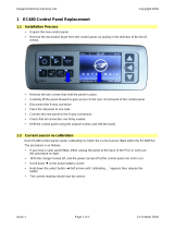
Instrument
Owner’s
Handbook
Document number: 81037-4
Date: 1st August 2002
PDF test 81037_4.book Page 5 Friday, July 26, 2002 11:08 AM

Raymarine, ST60 and SeaTalk are trademarks of Raymarine Limited
© Handbook contents copyright Raymarine Limited 2002
PDF test 81037_4.book Page 6 Friday, July 26, 2002 11:08 AM

i
Important information
Safety notices
WARNING: Product installation & operation
This equipment must be installed and operated in accordance with
the Raymarine instructions provided. Failure to do so could result in
personal injury, damage to your boat and/or poor product
performance.
WARNING: Electrical safety
Make sure you have switched off the power supply before you start
installing this product.
WARNING:
Although we have designed this product to be accurate and reliable,
many factors can affect its performance. Therefore, it should serve
only as an aid to navigation and should never replace commonsense
and navigational judgement. Always maintain a permanent watch
so you can respond to situations as they develop.
EMC conformance
All Raymarine equipment and accessories are designed to the best
industry standards for use in the recreational marine environment.
The design and manufacture of Raymarine equipment and accessories
conform to the appropriate Electromagnetic Compatibility (EMC)
standards, but correct installation is required to ensure that performance
is not compromised.
Handbook information
To the best of our knowledge, the information in this handbook was
correct when it went to press. However, Raymarine cannot accept
liability for any inaccuracies or omissions it may contain.
In addition, our policy of continuous product improvement may change
specifications without notice. Therefore, Raymarine cannot accept
liability for any differences between the product and the handbook.
PDF test 81037_4.book Page i Friday, July 26, 2002 11:08 AM

ii ST60 Speed Instrument Owner’s Manual
PDF test 81037_4.book Page ii Friday, July 26, 2002 11:08 AM

iii
Contents
Important information ............................................................................. i
Safety notices ................................................................................. i
EMC conformance ........................................................................ i
Handbook information .................................................................. i
Introduction .......................................................................................... vii
Data inputs ..................................................................................vii
SeaTalk .................................................................................vii
Stand alone operation ...........................................................viii
Remote control ..........................................................................viii
Mounting options .......................................................................viii
Parts supplied ...............................................................................ix
Chapter 1: Operation .........................................................................................1
1.1 Getting started ............................................................................... 1
Displayed information .................................................................. 1
1.2 Normal operation .......................................................................... 1
Speed information ........................................................................ 1
Current speed .......................................................................... 1
Maximum speed ..................................................................... 2
Average speed ......................................................................... 2
Velocity made good (to windward) ......................................... 3
Speed over ground .................................................................. 3
Log, trip and water temperature .................................................... 3
Log .......................................................................................... 3
Trip .......................................................................................... 4
Water temperature ................................................................... 4
Timers ........................................................................................... 4
Race-start timers ..................................................................... 4
1.3 Display settings ............................................................................. 6
Illumination .................................................................................. 6
Contrast ......................................................................................... 6
1.4 Pop-up Pilot .................................................................................. 6
1.5 Remote control ............................................................................. 7
Chapter 2: Maintenance and Faultfinding ......................................................9
2.1 Maintenance ................................................................................. 9
Servicing and safety ...................................................................... 9
Instrument ..................................................................................... 9
Transducer .................................................................................... 9
Cabling ........................................................................................ 10
2.2 Fault finding ................................................................................ 10
Preliminary procedures ............................................................... 10
PDF test 81037_4.book Page iii Friday, July 26, 2002 11:08 AM

iv ST60 Speed Instrument Owner’s Manual
Fixing faults ................................................................................ 10
Technical support ........................................................................ 11
World wide web .................................................................... 11
Telephone help line ............................................................... 11
Help us to help you ................................................................ 11
Chapter 3: Installation .....................................................................................13
3.1 Planning your installation ........................................................... 13
Site requirements ........................................................................ 13
Transducer ............................................................................ 13
Instrument ............................................................................. 15
EMC Installation Guidelines ...................................................... 16
Suppression Ferrites .............................................................. 17
Connections to Other Equipment .......................................... 17
3.2 Procedures .................................................................................. 17
Unpacking ................................................................................... 17
Fitting the instrument .................................................................. 18
Surface mounting .................................................................. 18
Flush mounting ..................................................................... 19
Bracket mounting .................................................................. 22
Fitting transducer ........................................................................ 22
Running transducer cable ...................................................... 22
Connecting the instrument .......................................................... 23
Types of connection .............................................................. 23
Signal connections ................................................................ 24
Power supply connections .................................................... 24
Chapter 4: Calibration .....................................................................................27
4.1 Introduction ................................................................................ 27
EMC conformance ...................................................................... 27
Speed readings ............................................................................ 27
4.2 User calibration ........................................................................... 28
Procedure .................................................................................... 28
Set speed units ....................................................................... 28
Set resolution ........................................................................ 28
Set log units ........................................................................... 28
Setting the correct speed ....................................................... 28
Set temperature units ............................................................. 29
Temperature calibration ........................................................ 29
Timer buzzer ......................................................................... 29
Pop-up pilot ........................................................................... 32
Leaving User calibration ....................................................... 32
PDF test 81037_4.book Page iv Friday, July 26, 2002 11:08 AM

v
4.3 Intermediate calibration .............................................................. 32
Speed calibration ........................................................................ 33
Leaving Intermediate calibration ................................................ 36
4.4 Dealer calibration ....................................................................... 36
User calibration on/off ................................................................ 36
Response settings ........................................................................ 38
Boat show mode .......................................................................... 38
Factory defaults .......................................................................... 38
Leaving Dealer calibration ......................................................... 38
PDF test 81037_4.book Page v Friday, July 26, 2002 11:08 AM

vi ST60 Speed Instrument Owner’s Manual
PDF test 81037_4.book Page vi Friday, July 26, 2002 11:08 AM

vii
Introduction
Thank you for purchasing a Raymarine product. We are sure your ST60
instrument will give you many years of trouble-free operation.
This handbook describes how to install and use the Raymarine ST60
Speed instrument. This instrument provides accurate speed, log, trip and
timer information, on a high quality Liquid Crystal Display (LCD). The
instrument is constructed in a rugged weather-proofed case to provide
reliable performance, even under the most demanding conditions.
Data inputs
The ST60 Speed instrument receives data either from an appropriate
speed transducer and/or from a SeaTalk instrumentation system.
SeaTalk
SeaTalk enables a number of compatible instruments to operate as a
single, integrated navigational system. Instruments in a SeaTalk system
are linked by means of a single cable, which feeds both power and data.
Instruments can therefore be added to the system by plugging them into
the network. SeaTalk is flexible enough to adapt to any number of
compatible instruments without requiring a central processor. SeaTalk
can also communicate via an interface, with non-SeaTalk equipment
using the internationally-accepted National Marine Electronics
Association (NMEA) protocol.
D4322-3
PDF test 81037_4.book Page vii Friday, July 26, 2002 11:08 AM

viii ST60 Speed Instrument Owner’s Manual
In a SeaTalk system, each instrument can be either a master or dedicated
repeater unit. A master instrument is directly connected to a transducer
(the device that provides the raw data), and provides data and control for
the service it is providing, to all other equipment on the SeaTalk network.
A slave instrument is not directly connected to a transducer but repeats
information provided by other equipment in the SeaTalk network.
The ST60 Speed instrument can fulfil both master and repeater roles.
Stand alone operation
In Stand alone operation, the ST60 Speed instrument is connected only to
the relevant transducer and does not display information from, or provide
information to, any other instruments.
Remote control
When connected to SeaTalk, the ST60 Speed instrument can be
controlled remotely by a SeaTalk Remote Keypad Unit, to provide
instant remote access to the various display readouts.
Mounting options
If you do not want to surface mount your ST60 instrument, options are
available for:
• Flush mounting. If you have ordered the flush mounting option a low-
profile bezel and four fixing screws are also provided.
• Bracket mounting.
PDF test 81037_4.book Page viii Friday, July 26, 2002 11:08 AM

ix
Parts supplied
Unpack your ST60 instrument and check that the following items are
present:
• Item 1, ST60 Speed instrument fitted with standard bezel for
surface mounting.
• Item 2, Fixing studs (2).
• Item 3, Thumb nuts (2).
• Item 4, Gasket.
• Item 5, Speed transducer, plus bung (not illustrated).
• Item 6, SeaTalk interconnection cable.
• Item 7, Power cable.
• Item 8, Instrument Cover.
• Item 9, Owner’s Handbook. A Warranty document and fitting
templates are included in this Handbook.
• Item 10, Cue Card.
Spare spade terminals are also provided, to re-terminate the transducer
cable if it has to be cut to facilitate installation.
Note: Theabove packinglist isforan ST60Speed system.Where an
instrumentis purchasedseparately,a transducer isnot included.
PDF test 81037_4.book Page ix Friday, July 26, 2002 11:08 AM

x ST60 Speed Instrument Owner’s Manual
D4439-3
ST60
Speed
Instrument
Owner's
Handbook
1
4
8
32
32
5
6
7
9
10
PDF test 81037_4.book Page x Friday, July 26, 2002 11:08 AM

Chapter 1: Operation 1
Chapter 1: Operation
1.1 Getting started
Displayed information
Your ST60 Speed instrument provides the following:
• Speed information.
• Log, trip and water temperature information.
• Count-up and race-start timers.
CAUTION:Calibration requirement
The ST60 Speed instrument is calibrated to default settings when
supplied. To ensure optimum performance on your boat, this
product MUST be calibrated before use. Do NOT use the product
until it has been calibrated using the procedures in Chapter 4,
Calibration.
1.2 Normal operation
Use the flow charts in this Chapter to operate your ST60 Speed
instrument. The flow charts show the sequence of key presses and
displays for the various operating tasks. All key presses are momentary
unless otherwise stated.
Speed information
The speed key gives access to current speed, maximum speed, average
speed, velocity made good (VMG) and speed over ground (SOG)
information. Refer to the Using speed key flow diagram to access the
information you want.
Current speed
Speed measurement units can be either knots (KTS), miles per hour (MPH)
or kilometres per hour (KMH). The required units are selected during user
calibration (see Chapter4,Calibration).
PDF test 81037_4.book Page 1 Friday, July 26, 2002 11:08 AM

2 ST60 Speed Instrument Owner’s Manual
Maximum speed
The maximum speed is reset at power up. It can also be reset manually by
pressing the reset key for 3 seconds. The display shows the maximum
recorded speed since the last reset. This screen times-out to current speed
if no user action occurs for 7 seconds.
Average speed
The average speed is reset at power up. It can also be reset manually by
pressing the reset key for 3 seconds. The display shows the average
speed calculated since the last reset. This screen times-out to current
speed if no user action occurs for 7 seconds.
speed
speed
speed
speed
speed
Current
speed
Maximum
speed
Average speed
Velocity made
good
Speed over
ground
7 second
timeout
7 second
timeout
speed
Using the speed key
D4363-2
to reset
Press for
3 s
reset
PDF test 81037_4.book Page 2 Friday, July 26, 2002 11:08 AM

Chapter 1: Operation 3
Velocity made good (to windward)
Velocity made good (VMG) information is available if your ST60 Speed
instrument is part of a SeaTalk system to which a SeaTalk-compatible
wind instrument is also connected.
Speed over ground
Speed over ground (SOG)information is available if your ST60 Speed
instrument is part of a SeaTalk system to which a suitable GPS is also
connected.
Log, trip and water temperature
The trip key gives access to log, trip and water temperature information.
Refer to the Usingtripkeyflow diagram to access the information you
want.
Log
The Log screen shows the total distance covered by the vessel since the
ST60 Speed instrument was fitted.
trip
trip
trip
for 3 s to return
TRIP value to 0
Using trip key
D4364-2
Log
Trip distance
Water
temperature
trip
Press
reset
PDF test 81037_4.book Page 3 Friday, July 26, 2002 11:08 AM

4 ST60 Speed Instrument Owner’s Manual
Trip
The trip distance is reset at power up and may also be reset manually, by
pressing the reset key for 3 seconds. The display shows the distance
covered since the last reset.
Note: Thetripdistancecanbe resetonlyifthe instrumentisa master,
i.e. connected toaspeed transducer.
Water temperature
The water temperature is shown in either degrees Celsius or Fahrenheit,
as set during calibration (see Chapter 4,Calibration).
Timers
The timer key gives access to a count-up timer and to two race-start
timers. Times are either in seconds (S)orminutes(M), depending on the
counter values.
Refer to the Using timerkey flow diagram to display the required timer.
Once you have selected the required timer display, press the reset key to
start the timer running. When a timer is running, the delimiter (i.e. ‘.’or
‘:’) flashes. For lap timing, press the reset key. To stop and reset a timer
to the start value, hold down the reset key for 1 second.
Once a timer is running, you can leave the timer page and select any other
display. The counter will continue to run in the background.
Race-start timers
You can set each race-start timer to any whole-minute value from 1 to 15
minutes.
Note: When the instrument is first installed, the race-start timersare set
to 4 and5 minutesrespectively.
To set a race-start timer:
1. Use the timer key as shown in the Using timer key flow diagram to
select the required race-start timer.
2. Simultaneously press the timer and reset keys to enter the race-start
timer adjust mode.
3. Use either the timer or reset key to set the required value.
4. Simultaneously press the timer and reset keys to save the value and
leave the race-start timer adjust mode
PDF test 81037_4.book Page 4 Friday, July 26, 2002 11:08 AM

Chapter 1: Operation 5
If you are using one of the race-start timers and the timer buzzer is
enabled, the buzzer will:
• Double-beep every minute.
• Beep three times at the start of the last 30 seconds.
• Beep once for each of the last 10 seconds.
• Beep for 2 seconds at zero.
The timer buzzer is enabled or disabled as part of the calibration
procedure (see Chapter4, Calibration).
Note: Afterarace-starttimerhascounted-downtozero,itwillthenstart
countingup.
D4365-3
Count-up
timer
Race-start
timer 1
Race-start
timer 2
timer
or for 1 s to reset timer to the start value.
Press
either momentarily
to start timer, or for lap time (when running)
reset
timer
to decrease the value
reset
to increase the value
timer
timer
timer
To enter/leave
adjust mode, press
timer
reset
and
momentarily
Race-start timer adjust
To set a different value, press
timer
reset
and
momentarily
To enter/leave
adjust mode, press
Using timer key
PDF test 81037_4.book Page 5 Friday, July 26, 2002 11:08 AM

6 ST60 Speed Instrument Owner’s Manual
1.3 Display settings
Illumination
When the instrument is first powered up, the display illumination is set to
its lowest (courtesy) level to facilitate initial access to the keys. To adjust
the level of illumination:
1. Hold down the speed key for approximately one second, to enter the
illumination-adjust mode.
2. There are four preset illumination levels. Press the speed key to
cycle through the these levels until you reach the level you want.
3. Press any other key to leave the illumination-adjust mode.
Note: Thedisplay willtime outto normaloperation7 seconds afterthe
last keypress.
Contrast
To adjust the display contrast:
1. Hold down the speed key for approximately two seconds, to enter
the contrast-adjust mode.
2. There are four preset contrast settings. Press the speed keytocycle
through the these settings until you achieve optimum display quality.
3. Press any other key to leave the contrast-adjust mode.
Note: Thedisplay willtime outto normaloperation7 seconds afterthe
last keypress.
1.4 Pop-up Pilot
A Pop-up Pilot facility enables instruments connected to SeaTalk to con-
stantly monitor any changes to the autopilot mode and to the course set-
tings. If one of these parameters changes, the new value is immediately
displayed on the ST60 instrument for 5 seconds, after which time the dis-
play reverts to the previous display.
This facility can be enabled or disabled during User calibration (see
Chapter4, Calibration).
PDF test 81037_4.book Page 6 Friday, July 26, 2002 11:08 AM

Chapter 1: Operation 7
1.5 Remote control
When it is connected to SeaTalk, the ST60 Speed instrument can be
controlled remotely with a SeaTalk Remote Keypad Unit. Remote
control of an instrument is indicated by a REMOTE legend on the display,
to indicate that the keypad has control.
Details on how to use the remote control facility can be found in the
SeaTalkRemote Keypad Owner’s Handbook.
PDF test 81037_4.book Page 7 Friday, July 26, 2002 11:08 AM

8 ST60 Speed Instrument Owner’s Manual
PDF test 81037_4.book Page 8 Friday, July 26, 2002 11:08 AM
/