
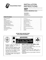
Revision: P-UD&APD (02-20) PN270285R17
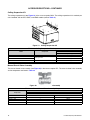
MODELS APD AND UDAP: STANDARD POWER VENT FAN TYPE
MODEL UDBP: STANDARD POWER VENT BLOWER TYPE
MODEL UDAS: SEPARATED COMBUSTION FAN TYPE
MODEL UDBS: SEPARATED COMBUSTION BLOWER TYPE
Supersedes: P-UD&APD (07-19) PN270285R16
IMPORTANT
1. Always include complete model and serial number so that any specification change can be considered for parts replacement.
It can save time and expense.
2. In keeping with our policy of continuous product improvement, we reserve the right to alter any information shown here.
Specifications are subject to change without notice.
3. We reserve the right to substitute functional replacements.
4. Order by Part Number (PN) not by option designation.
REPLACEMENT PARTS FOR UNIT HEATERS
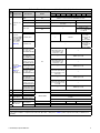
TABLE OF CONTENTS
WARRANTY (ALL MODELS) ..................................................................2
REFERENCES .............................................................................2
RATING PLATE .............................................................................2
SERIAL NUMBERS .........................................................................3
ELECTRICAL COMPONENTS .................................................................4
BLOWER COMPONENTS ...................................................................13
CABINET COMPONENTS ...................................................................22
VENTER AND FLUE WRAPPER COMPONENTS .................................................25
HEAT EXCHANGER AND BURNER ASSEMBLY COMPONENTS ....................................28
VENTING AND COMBUSTION AIR KIT COMPONENTS (MODELS UDAS AND UDBS) ..................31
ACCESSORIES/OPTIONS ...................................................................33
THERMOSTATS AND THERMOSTAT ACCESSORIES .............................................39

2
P-UD&APD (02-20) PN270285R17
WARRANTY (ALL MODELS)
• One-year limited warranty on the heater.
• Nine-year extended limited warranty on the heat exchanger, burner, and flue collection box assembly.
• Four-year extended limited warranty on all electrical and mechanical operating components (with the exception
of blower belts).
• Contact your distributor for details.
REFERENCES
Table 1. Related Technical Manuals Available from Factory Distributor
Type Form PN
Installation/operation (all power vent and separated combustion unit heaters) D300519 I-UDA&APD 195673
Vent installation (all power vent fan and blower type unit heaters) I-UD&APD Series V-PV 195675
Vent installation (separated combustion fan and blower type unit heaters) I-UD-V-SC 195676
Vent installation (power vent fan type unit heater with option AV6, common vent) I-UD-V-CV 195677
High-altitude kit installation I-UD&APD Series HA 197081
Gas conversion kit installation CP-UD&APD Series GC 197209
Installation/operation (all power vent and separated combustion blower type unit heaters) I-UDB 202658
Replacement parts P-UD&APD 263995
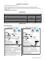
RATING PLATE
Sample Rating Plates
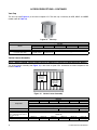
Standard Power Fan Type Unit
MADE IN MEXICO
UNIT HEATER NRTL
CATEGORY [ Z ]
ANSI Z83.8 [ A ] CSA 2.6 [ A’ ] UNIT HEATER
CSA .10.96 U.S. (2nd Ed.) UNIT HEATERS FOR RESIDENTIAL INSTALLATION
MODEL [ B ] [ C ]
SERIAL NO.
[ D ] VOLTS [ D ] PH [ D ] HZ MAXIMUM TOTAL INPUT [ D ] AMPS
TYPE OF GAS: [ E ]
FOR USE AT 0-2000 FEET, 0-610 METERS OF ALTITUDE.
ORIFICE SIZE [ F ] DRILL HAS BEEN FACTORY ADJUSTED
SEA LEVEL
NORMAL INPUT
[ J ] BTU/HR
THERMAL OUTPUT CAPACITY
[ L ] BTU/HR
MINIMUM INPUT(-2 MODELS)
[ M ] BTU/HR
NORMAL MANIFOLD PRESSURE
[ G ] IN.W.C.
MIN. PERMISSIBLE GAS SUPPLY PRESSURE
FOR PURPOSE OF INPUT ADJUSTMENT.
[ H ] IN.W.C.
CLEARANCES TO COMBUSTIBLE CONSTRUCTION: TOP-[ N ] “,
FLUE CONNECTION-6ʺ, CONTROL SIDE-18ʺ, OPP. SIDE-[ P ] “,
BOTTOM-1ʺ, FRONT-36ʺ.
FOR ALTERNATE INSTALLATIONS USE THE LATEST EDITIONS OF
THE APPROPRIATE STANDARD LISTED BELOW:
FOR AIRCRAFT HANGARS USE STANDARD ANSI/NFPA 409
FOR PARKING STRUCTURES USE STANDARD ANSI/NFPA 88A
FOR REPAIR GARAGES USE STANDARD ANSI/NFPA 88B
THIS UNIT IS NOT FOR USE WITH DUCTS.
THIS UNIT IS NOT FOR USE WITH FILTERS.
IN THE EVENT THE FLAME ROLLOUT SENSOR CAUSES THE
HEATER TO SHUT OFF, DETERMINE AND CORRECT THE CAUSE.
FAILURE TO DO SO COULD RESULT IN PERSONAL INJURY OR
DEATH. TO RESET, DEPRESS THE BUTTON ON THE SENSOR
LOCATED ON THE BURNER BOX ASSEMBLY.
MADE IN MEXICO
NRTL
UNIT HEATER
CATEGORY [ Z ]
ANSI Z83.8 [ A ] CSA 2.6 [ A’ ] UNIT HEATER
MODEL [ B ] [ C ]
SERIAL NO.
[ K ] HP
[ D ] VOLTS [ D ] PH [ D ] HZ MAXIMUM TOTAL INPUT [ D ] AMPS
TYPE OF GAS: [ E ]
FOR USE AT 0-2000 FEET, 0-610 METERS OF ALTITUDE.
ORIFICE SIZE [ F ] DRILL
SEA LEVEL
NORMAL INPUT
[ J ] BTU/HR
THERMAL OUTPUT CAPACITY
[ L ] BTU/HR
MINIMUM INPUT(-2 MODELS)
[ M ] BTU/HR
NORMAL MANIFOLD PRESSURE
[ G ] IN.W.C.
MIN. PERMISSIBLE GAS SUPPLY PRESSURE
FOR PURPOSE OF INPUT ADJUSTMENT.
[ H ] IN.W.C.
TEMPERATURE RISE RANGE FROM [ Q ] DEG. F. TO [ R ] DEG. F.
MAXIMUM EXTERNAL STATIC PRESSURE [ S ] IN. W.C.
CLEARANCES TO COMBUSTIBLE CONSTRUCTION: TOP-[ N ] “, FLUE
CONNECTION-6ʺ, CONTROL SIDE-18ʺ, OPP. SIDE-[ P ] “, BOTTOM-1ʺ, FRONT-36ʺ
FOR ALTERNATE INSTALLATIONS USE THE LATEST EDITIONS OF THE
APPROPRIATE STANDARD LISTED BELOW:
FOR AIRCRAFT HANGARS USE STANDARD ANSI/NFPA 409
FOR PARKING STRUCTURES USE STANDARD ANSI/NFPA 88A
FOR REPAIR GARAGES USE STANDARD ANSI/NFPA 88B
INSTALLATION OF THIS UNIT IN AIRCRAFT HANGERS IN ACCORDANCE WITH
THE REQUIREMENTS OF THE ENFORCING AUTHORITIES AND IN PUBLIC
GARAGES IN ACCORDANCE WITH THE CAN/CGA-B149 (.1 OR .2 ) CODES.
THIS UNIT IS NOT FOR USE WITH FILTERS.
THIS UNIT MAY BE USED WITH DUCTS.
Standard Power Blower Type Unit

3
P-UD&APD (02-20) PN270285R17
Rating Plate Key
A = Date of ANSI standard
A’ = Date of CSA standard
B = Model number
C = Month and year of manufacture
D = Voltage, phase, 60 Hertz, maximum total input amps
E = Natural gas or propane
F = Orice size
G = Manifold pressure (3.5 IN WC natural gas, 10 IN WC propane)
H = Minimum gas supply pressure (5 IN WC natural gas, 11 IN WC propane)
J = BTU normal input sea level
K = Blower motor horsepower
L = BTU thermal output sea level
M = BTU minimum input sea level
N = Top clearance
P = Left side clearance
Q = Temperature rise from (°F)
R = Temperature rise to (°F)
S = Maximum external static pressure (IN WC)
Z = Category
SERIAL NUMBERS
Serial number format changed in June of 2015. Use the following information to decode system serial numbers:
Decoding a System Serial Number for ALL Models BEFORE June 2015
Serial number sample: BLK 79 6E N 00000
Elements key number: 1 I 2 I 3 I 4 I 5
Key:
1 = Date code (refer to Table 2)
2 = Type of ignition system
3 = Type of gas valve
4 = Gas (N = natural, L = propane)
5 = Consecutive number
Decoding a System Serial Number for ALL Models AFTER May 2015
Serial number sample: BOG 3060 00000
Elements key number: 1 | 2 | 3
Key:
1 = Date code (refer to Table 2)
2 = Plant of manufacture (3060 = Mercer, 3062 = Monterrey)
3 = Consecutive number

4
P-UD&APD (02-20) PN270285R17
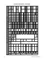
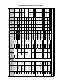
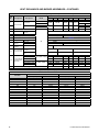
Table 2. Serial Number Date Codes (Month and Year)
Year
Month
JAN FEB MAR APR MAY JUN JUL AUG SEP OCT NOV DEC
2002
BBA BBB BBC BBD BBE BBF BBG BBH BBI BBJ BBK BBL
2003
BCA BCB BCC BCD BCE BCF BCG BCH BCI BCJ BCK BCL
2004
BDA BDB BDC BDD BDE BDF BDG BDH BDI BDJ BDK BDL
2005
BEA BEB BEC BED BEE BEF BEG BEH BEI BEJ BEK BEL
2006
BFA BFB BFC BFD BFE BFF BFG BFH BFI BFJ BFK BFL
2007
BGA BGB BGC BGD BGE BGF BGG BGH BGI BGJ BGK BGL
2008
BHA BHB BHC BHD BHE BHF BHG BHH BHI BHJ BHK BHL
2009
BIA BIB BIC BID BIE BIF BIG BIH BII BIJ BIK BIL
2010
BJA BJB BJC BJD BJE BJF BJG BJH BJI BJJ BJK BJL
2011
BKA BKB BKC BKD BKE BKF BKG BKH BKI BKJ BKK BKL
2012
BLA BLB BLC BLD BLE BLF BLG BLH BLI BLJ BLK BLL
2013
BMA BMB BMC BMD BME BMF BMG BMH BMI BMJ BMK BML
2014
BNA BNB BNC BND BNE BNF BNG BNH BNI BNJ BNK BNL
2015
BOA BOB BOC BOD BOE BOF BOG BOH BOI BOJ BOK BOL
2016
BPA BPB BPC BPD BPE BPF BPG BPH BPI BPJ BPK BPL
2017
BQA BQB BQC BQD BQE BQF BQG BQH BQI BQJ BQK BQL
2018
BRA BRB BRC BRD BRE BRF BRG BRH BRI BRJ BRK BRL
2019
BSA BSB BSC BSD BSE BSF BSG BSH BSI BSJ BSK BSL
2020
BTA BTB BTC BTD BTE BTF BTG BTH BTI BTJ BTK BTL
SERIAL NUMBERS—CONTINUED
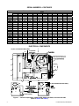
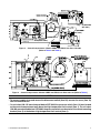
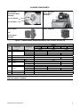
ELECTRICAL COMPONENTS
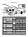
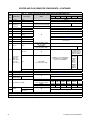
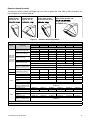
Figure 1. Control Compartment—Models APD, UDAP, and UDAS, Unit Sizes 030–400
(Refer to Table 3 and Table 4)
Separated Combustion unit
has a collar for combustion
4
14 (AFTER
AUG 2003)
14 (030–125 BEFORE SEP 2003)
8
1
2
3
19
12
16
17
20
18
14 (150–400 BEFORE SEP 2003)
13
7
13 (OPTIONAL)
5
6
9
10
7
10

5
P-UD&APD (02-20) PN270285R17
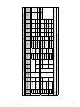
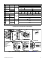
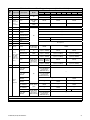
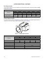
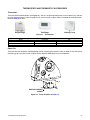
Figure 2. Control Compartment—Models UDBP and UDBS, Unit Sizes 150–400
(Refer to Table 3 and Table 4)
Figure 3. Control Compartment—Models UDBP and UDBS, Unit Sizes 030–125 (Refer to Table 3)
NOTE:
• To connect supply wires and access the disconnect switch (item 20), remove the cover (item 18)
from the electrical box.
• On unit sizes 030-125 manufactured before SEP 2003, the pressure switch (item 14) was located
on the control compartment wall above the high temperature limit control (item 1). On unit sizes
150-400 manufactured before SEP 2003, the pressure switch was located on the control mounting
bracket (item 5) at the bottom high temperature limit control (item 1).
Top View Separated
Combustion Blower
Type Control
Bracket Assy
Top View Power
Vent Blower Type
Control Bracket
Assy
10
14 (BEFORE
SEP 2003)
18 (UDBS ONLY)
7
16
17
5
6
14 (BEFORE
SEP 2003)
Starter or Contactor
10
7
Starter or Contactor
(UDBS only)
Capacitor
19 (UDBS ONLY)
20 (UDBS ONLY)
9
8
14
15
1
2
3
Orifice
1
2
3
8
16
17
14
15
18 (UDBS ONLY)18 (UDBS ONLY)
20 (UDBS ONLY)
19 (UDBS ONLY)
9
5
6
7
10

6
P-UD&APD (02-20) PN270285R17
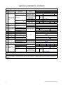
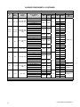
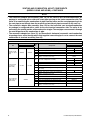
Table 3. Electrical Components (Unit Sizes 030–125)
Item
No.
Component Description Model
Unit Size
030 045 060 075 100 125
PN
1
High temperature
limit control, auto
reset*
180°F
APD, UDAP, UDAS
— 45602 —
200°F, yellow
— 85449
Low noise: APD-45LN,
UDAP-45LN
(both with option AL2B)
— 85449 —
UDBP, UDBS — 85449 —
220°F, blue
APD, UDAP, UDAS 96512 —
UDBP, UDBS
— 96512 — 96512 —
275°F, green 201961 — 201961
2 Plate Limit control All 170025
3 Bracket Limit control
APD, UDAP, UDAS 170026
UDBP, UDBS 201771
4
Flame rollout
switch, manual
reset*
210°F/−31°F, violet
APD, UDAP, UDAS
197033 —
225°F/−31°F, red — 196949 —
250°F/−31°F, yellow — 196950
5 Bracket Control mounting
All
195551
6 Gasket Control mounting bracket 195664
7 Circuit board
DSI ignition control, UTC
1097-210, serial No. code 79
195265
7A
Fuse**
Circuit board 201685
8 Sensor Flame 195292
9 Ignitor Electrode assembly 1024503 175272
10 Transformer
25VA, 115V APD, UDAP, UDAS 175265
40 VA, 115V
APD, UDAP, UDAS
(each with option CL31)
194808
40 VA, 208–230V/1PH 194536
11 Stepdown transformer Refer to Table 4
12
Fan motor (for
spacing, refer to
Table 5)
115V, open
APD, UDAP, UDAS
196240 196241 196242 196243 196244
208/230V, open***
196826 195302
115V, TEFC
APD, UDAP, UDAS
(each with option AL14)
203310 203724
115V
Low noise: APD-45LN,
UDAP-45LN
(both with option AL2B)
— 203030 —
13 Capacitor, fan motor Refer to Table 4
*Color listed is the color of the identifying dot on the label.
**May be replaced with field-supplied type ATC or ATO 3-amp fuse (color code: violet).
***When inventory of the 208/230V fan motors is depleted, they will no longer be available as replacement parts. A replacement 115V
motor and the installation of stepdown transformer kit option CG1 or CG2 (refer to Table 7) will be required. Check with your Distributor for
availability.
ELECTRICAL COMPONENTS—CONTINUED

7
P-UD&APD (02-20) PN270285R17
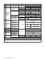
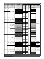
Table 3. Electrical Components (Unit Sizes 030–125)
Item
No.
Component Description Model
Unit Size
030 045 060 075 100 125
PN
14
Pressure switch,
0–6000 feet,
H/W #IS2 (for
elevations above
6000 feet, refer
to Table 23)*
0.4 IN WC, green
APD, UDAP 197030 — 197030
UDBP 197030 — 197030
UDBS 197030 — 197030 —
0.45 IN WC, pink UDAS, UDBS — 197032
0.5 IN WC, orange
APD, UDAP — 196388 —
APD-CV, UDAP-CV
(both with option AV6)
— 196388 —
UDBP — 196388 —
UDBS — 196388 — 196388 —
0.55 IN WC, white
APD-CV, UDAP-CV
(both with option AV6)
— 196362 —
0.6 IN WC, light blue
— 197029 —
UDBS — 197029 —
0.65 IN WC, yellow
APD-CV, UDAP-CV
(both with option AV6)
197028 —
UDAS 197028 —
15
Gas valve
(refer to Serial
Numbers and to
Table 6 for codes
in parentheses)
One-stage, natural gas,
1/2 × 1/2
(MH VR8215T1239)
All
260603 (6E)
One-stage, propane,
1/2 × 1/2
(MH VR8215T5214)
263999 (9E)
Two-stage, natural gas,
1/2 × 1/2
(MH VR8205N2921)
— 197066 (Y8 or 4A)
Two-stage, propane,
1/2 × 1/2
(MH VR8205N2913)
— 197064 (Y6 or 2A)
16 Terminal board 24V, 5-pole 196813
17 Gasket Terminal board
UDAS, UDBS
196327
18 Cover Electrical box 201945
19 Door switch
Interlock
(Carling PN TA22B-TLB-B)
217262
20
Disconnect
switch
For units manufactured
after SEP 2006
101902
For units manufactured
before OCT 2006
201946
21
Wiring harness
(not shown)
9-pin terminal
APD, UDAP, UDAS 197148 197199 197149
UDBP, UDBS 203523 203524 203525
22 5-pin terminal All 195653
*Color listed is the color of the identifying dot on the label.
**May be replaced with field-supplied type ATC or ATO 3-amp fuse (color code: violet).
***When inventory of the 208/230V fan motors is depleted, they will no longer be available as replacement parts. A replacement 115V
motor and the installation of stepdown transformer kit option CG1 or CG2 (refer to Table 7) will be required. Check with your Distributor for
availability.
—Continued

8
P-UD&APD (02-20) PN270285R17
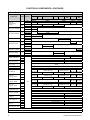
ELECTRICAL COMPONENTS—CONTINUED
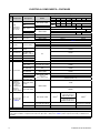
Table 4. Electrical Components (Unit Sizes 150–400)
Item
No.
Component Description Model
Unit Size
150 175 200 225 250 300 350 400
PN
1
High
temperature
limit control,
auto reset*
160°F, red
APD, UDAP, UDAS
— 82091 — 82091 —
180°F 45602
— 45602 — 45602 — 45602
UDBP, UDBS — 45602 —
200°F, yellow
APD, UDAP, UDAS — 85449 —
UDBP, UDBS
— 85449
240°F, silver — 202048 — 202048 —
250°F, orange — 201962 —
2 Plate Limit control All 170025
3 Bracket Limit control
APD, UDAP, UDAS 170026
UDBP, UDBS 201771 202701
4 Flame rollout switch Refer to Table 3
5 Bracket Control mounting
APD, UDAP, UDAS 195294
UDBP 202736
UDBS 195294
6 Gasket
Control mounting
bracket
All
195669
7 Circuit board
DSI ignition control,
UTC 1097-210,
serial No. code 79
195265
7A
Fuse**
Circuit board 201685
8 Sensor Flame 195292
9 Ignitor Electrode assembly 175272
10 Transformer
25VA, 115V APD, UDAP, UDAS 175265
40 VA, 115V
APD, UDAP, UDAS
(each with option CL31)
194808
40 VA,
208–230V/1PH
All
194536
40 VA,
208–230V/3PH
UDBP, UDBS 194536
25VA, 115V
APD, UDAP, UDAS
(each with
options D10 & D14)
175265
40VA, 115V 194808
40 VA,
208V–230V/1PH
194536 (quantity = 2)
11
Stepdown
transformer
(not located
in control
compartment—
hangs on
outside of
heater cabinet)
480V supply 120V,
1/2 kVA
UDBP, UDBS
11100
575V supply 120V 202056
12
Fan motor (for
spacing, refer
to Table 5)
115V, open APD, UDAP, UDAS
196245
†
271461
†
(units manufactured
after 19 SEP 2013)
196247
†
271585
(units manufactured
before 20 SEP 2013)
115V, TEFC
APD, UDAP, UDAS
(each with option AL14)
196824
196825
(must be Fasco REV D)
208/230V, open***
APD, UDAP, UDAS 195302 195303
*Color listed is the color of the identifying dot on the label.
**May be replaced with field-supplied type ATC or ATO 3-amp fuse (color code: violet).
***When inventory of the 208/230V fan motors is depleted, they will no longer be available as replacement parts. A replacement 115V
motor and the installation of stepdown transformer kit option CG1 or CG2 (refer to Table 7) will be required. Check with your Distributor for
availability.
†
Requires a new capacitor when replacing motor. Refer to item 13.

9
P-UD&APD (02-20) PN270285R17
Table 4. Electrical Components (Unit Sizes 150–400)
Item
No.
Component Description Model
Unit Size
150 175 200 225 250 300 350 400
PN
13
Capacitor, fan
motor
115V & 208/230V,
7.5μF
All 195643, for units manufactured before JUL 2019
115V, 7.5μF All (with option AL14) 195643 —
115V, 10μF All
207448, for units manufactured beginning
JUL 2019
—
115V, 15μF
All (with option AL14)
—
217031
All
217031, for units
manufactured beginning
JUL 2019
14
Pressure
switch, 0–6000
feet, H/W #IS2
(for elevations
above 6000
feet, refer to
Table 23)*
0.4 IN WC, green
All
197030 —
1.1 IN WC, blue — 201158
201158,
for units
manufactured
after
22 JUL 2009
1.4 IN WC, red —
201159,
for units
manufactured
before
23 JUL 2009
15
Gas valve
(refer to Serial
Numbers
and to
Table 6 for
codes in
parentheses)
One-stage, natural
gas, 1/2 × 1/2
(MH VR8215T1239)
260603
(6E, replacement for
serial number code
Y2, Z7, X7, or Z3)
—
One-stage, natural
gas, 3/4 × 3/4
(MH VR8305K4241)
— 196981 (Y3 or Z8)
One-stage,
propane, 1/2 × 1/2
(MH VR8215T5214)
263999
(9E, replacement for
serial number code
Y4, Z9, X9, or Z5)
—
One-stage,
propane, 3/4 × 3/4
(MH VR8305K4258)
— 196983 (Y5 or 1A)
Two-stage, natural
gas, 1/2 × 1/2
(MH VR8205N2921)
197066
(Y8 or 4A, replacement
for serial number code
X8 or Z4)
—
Two-stage, natural
gas, 3/4 × 3/4
(MH VR8305N4297)
— 197067 (Y9 or 5A)
Two-stage,
propane, 1/2 × 1/2
(MH VR8205N2913)
197064
(Y6 or 2A, replacement
for serial number code
Y1or Z6)
—
Two-stage,
propane, 3/4 × 3/4
(MH VR8305N4289)
— 197065 (Y7 or 3A)
16 Terminal board 24V, 5-pole 196813
17 Gasket Terminal board
UDAS, UDBS
196327
18 Cover Electrical box 201945
19 Door switch
Interlock (Carling
PN TA22B-TLB-B)
217262
20 Disconnect switch 101902 (replaced 202054)
21
Wiring harness
(not shown)
9-pin terminal
APD, UDAP, UDAS 201417 201418 201419
UDBP, UDBS 203526 203527 203528
22 5-pin terminal All 195656
*Color listed is the color of the identifying dot on the label.
**May be replaced with field-supplied type ATC or ATO 3-amp fuse (color code: violet).
***When inventory of the 208/230V fan motors is depleted, they will no longer be available as replacement parts. A replacement 115V
motor and the installation of stepdown transformer kit option CG1 or CG2 (refer to Table 7) will be required. Check with your Distributor for
availability.
—Continued

10
P-UD&APD (02-20) PN270285R17
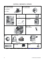
ELECTRICAL COMPONENTS—CONTINUED
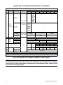
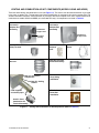
Figure 4. Individual Electrical Components (See Locations in Figure 1, Figure 2, and Figure 3)
Item 1: High Temperature
Limit Control, Auto Reset
Item 2: Bracket
Item 3: Plate
Item 4: Flame Rollout
Switch, Manual Reset
Item 7: Circuit Board Item 8: Flame Sensor
Item 9: Ignitor
Item 10: Transformer
Item 13: Fan
Motor Capacitor
Item 12: Fan Motor
Item 11: Stepdown
Transformer
Item 15: Gas Valve
Single-Stage Two-Stage
Item 14: Pressure
Switch
Item 16: Terminal Board
Item 19: Interlock
Door Switch
Item 20: Disconnect
Switch

11
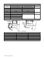
P-UD&APD (02-20) PN270285R17
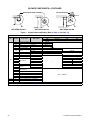
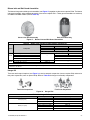
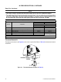
Table 5. Fan Blade/Motor Spacing and Fan Guard Type
Unit Size
Wire Fan Guard Type
Setscrew Torque
(inch-pounds ±10)
Standard Guard
(0.5-Inch (13-mm) Spacing)
Option AZ8 Guard
(0.334-Inch (8.5-mm) Spacing)
A = Fan Spacing (Inches (mm))*
030 1 (25)
80
045 9/16 (14) 1-1/16 (27)
045-LN 3/4 (19) —
060 1-1/2 (38) 1-3/4 (44)
075 2-1/8 (54) 1-1/2 (38)
100 2-3/8 (60)
120
125 2-5/16 (59) 2-1/8 (54)
150 2-3/8 (60)
— 130
175 2-1/8 (54)
200 1-5/8 (41)
225, 250, & 300 2 (51)
350 1-7/8 (48)
400 1-3/8 (35)
*See Figure 5.
A
Fan Blade
Sizes
030–250
Motor
Setscrew
A
Sizes
300–400
Motor
Fan
Blade
Setscrew
Figure 5. Fan Spacing
Table 6. Gas Valve Serial Numbers
PN Serial Number Code Replacement for Serial Number Code
196981 Y3 or Z8
196983 Y5 or 1A
197064 Y6 or 2A Y1 or Z6
197065 Y7 or 3A
197066 Y8 or 4A X8 or Z4
197067 Y9 or 5A
260603 6E Y2, Z7, X7, or Z3
263999 9E Y4, Z9, X9, or Z5
NOTE: Refer to Serial Numbers for code definitions.

12
P-UD&APD (02-20) PN270285R17
ELECTRICAL COMPONENTS—CONTINUED
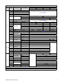
Table 7. Stepdown Transformer Kit Components (Same as Option CG1, CG2, or CG4)
Component
Model* Option**
Unit Size
030 045 060, 075 100 125
150, 175,
200
225, 250
300, 350,
400
PN
Stepdown
transformer kit
package
A
CG1 260919 260920 260921 260922 260923
CG2, CG4 197150 197151 197152 197153 197154
B
CG1 260924 260925 260926
—
CG2, CG4 202976 202977 202978
Transformer, 0.25kVA A
CG1 260927
—
CG2, CG4 11279
Transformer, 0.5kVA
A
CG1
—
260928
—
CG2, CG4 11100
B
CG1 260928
—
CG2, CG4 11100
Transformer, 0.75kVA A
CG1
—
260929
—
CG2, CG4 11217
Transformer, 1kVA
A
CG1
—
223462
—
CG2, CG4 16065
B
CG1
—
223462
—
CG2, CG4 16065
Transformer, 1.5kVA A
CG1
—
260930
CG2, CG4 197085
Transformer, 2kVA B
CG1
—
260931
—
CG2, CG4 202979
Common Parts
Bracket, transformer
A
All
197079 197080
B 197079 —
Gasket,
transformer bracket
A 236155
B 236155 —
Capscrew, hex head,
3/8 × 1 long
A
32253
Lockwasher, 3/8 5197
Flat washer, 3/8 6593
BX cable, 3/8
A
45097
(38ʺ long)
174394 (46ʺ long) 63292 (49ʺ long)
10460
(56ʺ long)
201465
(70ʺ long)
B 45097 (38ʺ long) 174394 (46ʺ long) 63292 (49ʺ long) —
Black wire,
14-gauge, 105°C
A
32520
(54ʺ long)
7208 (62ʺ long) 123150 (65ʺ long)
48862
(72ʺ long)
201466
(86ʺ long)
B 32520 (54ʺ long) 7208 (62ʺ long) 123150 (65ʺ long) —
White wire,
14-gauge, 105°C
A
201243
(54ʺ long)
201242 (62ʺ long) 123152 (65ʺ long)
48861
(72ʺ long)
201467
(86ʺ long)
B 201243 (54ʺ long) 201242 (62ʺ long) 123152 (65ʺ long) —
Green wire
14-gauge, 105°C
A
201241
(54ʺ long)
201240 (62ʺ long) 201468 (65ʺ long)
201462
(72ʺ long)
201469
(86ʺ long)
B 201241 (54ʺ long) 201240 (62ʺ long) 201468 (65ʺ long) —
Bushing, anti-short
A 16358 (quantity = 2)
B 16358 (quantity = 2) —
Connector, straight
A 16199
B 16202 (T&B #302) —
Connector,
90-degree
A 1417 (T&B #XC-290)
B 1417 (T&B #XC-290) —
Cable clamp, 1/2
A 16227 (Heyco #3328)
B 16227 (Heyco #3328) —
Screw, sheet metal,
#10 × 1/2
A 11813 (quantity = 3)
B 11813 (quantity = 3) —
Wire connector, 73B
A 16354 (Ideal #3-0253, quantity = 10)
B 16354 (Ideal #3-0253, quantity = 10) —
*A = models APD, UDAP, and UDAS. B = models UDBP and UDBS.
**Option CG1 is for 208V supply 120V, option CG2 is for 230V supply 120V, and option CG4 is for 460V supply 120V.

13
P-UD&APD (02-20) PN270285R17
BLOWER COMPONENTS
Table 8. Direct-Drive Blower Motor Assembly Components (Unit Sizes 030–125)
Item
No.
Component Description
Unit Size
030 045 060 075 100 125
PN
1 Motor assembly Direct-drive 202731 202732 202733
1A Motor
1/6-HP 201760 —
1/3-HP — 201761 —
3/4-HP — 201762
1B Motor band 51221
1C Support arm 51223 (quantity = 3) 220629 (quantity = 3)
1D Capscrew, hex head 1/4-20 × 1-1/2 long 51231
1E Nut, keps 1/4-20 7328
1F BX cable
3/8 × 30 long 2889 —
3/8 × 43 long — 174387
1G Bushing Anti-short (2) 16358
2 Capacitor
370V, 5µF 101917 —
370V, 7.5µF — 101918 15MFD
370V, 15µF — 201763
2A End cap Capacitor 82113
2B Bracket Capacitor strap 82114
Figure 6. Individual Blower Components (Refer to Table 8, Table 9, and Table 10)
NOTE: Motors that don’t list a contactor in Table 9 or Table 10 require a starter. If a contactor is
listed, the starter is optional.
Item 1: Direct-
Drive Blower Motor
Assembly
Item 2: Capacitor
Item 1A: Motor
Item 5: ContactorItem 3: Starter
and
Item 4: Starter
Overload
Item 1: Belt-Drive
Blower Motor
Assembly

14
P-UD&APD (02-20) PN270285R17
Table 9. Open-Type Belt-Drive Blower Motor Assembly (Unit Sizes 150–400)
Item 1A: Motor Item 3: Starter Item 4: Starter Overload Item 5: Contactor
HP
Full
Load
Amps
(FLA)
Manufacturer’s
Model
Frame
Size
Shaft
Size
(Inches)
Service
Factor
Power
Factor
Efficiency
Voltage/
Phase
PN
GE
Model
PN
Min
Amps
Max
Amps
GE
Model
PN
GE
Model
PN
1/4
4.6
BF2024 48/56
1/2
1.35 — 120/1
210611
CL00A310T-J 151146 4.00 6.30 RTA1-L 151191 42AF35AF 119626
2.3 1.15 63 59.0%
208/1 CL00A310T-L 151150
1.80 2.70 RTA1-J 151189 42AF35AG 119627
240/1 CL00A310T-S 151147
1.1
M3003 K48 1.35 72
74.0%
208/3 115864 CL00A310T-L 151150
1.00 1.50 RTA1-G 151187
—1.4 240/3
115864
CL00A310T-S 151147
0.75 81.0% 480/3 CL00A310T-J 151146 0.65 1.10 RTA1-F 151186
1/3
6.0
BF2034 48/56
1.35
—
120/1
202091
CL00A310T-J 151146 4.00 6.30 RTA1-L 151191 42AF35AF 119626
3.0
208/1 CL00A310T-L 151150
2.50 4.10 RTA1-K 151190 42AF35AG 119627
240/1 CL00A310T-S 151147
1.4
M3007 K48
208/3
115863
CL00A310T-L 151150 1.80 2.70 RTA1-J 151189
—1.6 240/3 CL00A310T-S 151147 1.30 1.90 RTA1-H 151188
0.8 480/3 CL00A310T-J 151146 0.65 1.10 RTA1-F 151186
1/2
8.8
BF2054 56Z
5/8
1.15
120/1
102627
CL00A310T-J 151146 8.00 12.00 RTA1-N 151193 42AF35AF 119626
5.1 208/1 CL00A310T-L 151150
4.00 6.30 RTA1-L 151191
42AF35AG 119627
4.4 240/1 CL00A310T-S 151147
2.5
H880 LA56
1.25
208/3
159183
CL00A310T-L 151150 1.80 2.70 RTA1-J 151189
3.0 240/3 CL00A310T-S 151147 2.50 4.10 RTA1-K 151190
1.5 480/3
CL00A310T-J 151146
1.30 1.90 RTA1-H 151188 42AF35AF 119626
0.9 H991 H56 575/3 202089 0.65 1.10 RTA1-F 151186 — —
3/4
11.0
AOS-C426V1 B56
1.25
120/1
93548
CL01A310T-J 151151 10.00 16.00 RTA1-P 151194 42AF35AF 119626
5.5 208/1 CL00A310T-L 151150
4.00 6.30 RTA1-L 151191
42AF35AG 119627
5.4 240/1 CL00A310T-S 151147
2.9
312P696 D56
208/3
36951
CL00A310T-L 151150
2.50 4.10 RTA1-K 151190
2.6 240/3 CL00A310T-S 151147
1.3 480/3
CL00A310T-J 151146
1.00 1.50 RTA1-G 151187 42AF35AF 119626
1.0 H992 H56 575/3 202090 0.65 1.10 RTA1-F 151186 — —
1
13.0
C523 H56 1.25
120/1
13685
CL01A310T-J 151151 10.00 16.00 RTA1-P 151194 42AF35AF 119626
7.5 208/1 CL00A310T-L 151150
5.50 8.50 RTA1-M 151192
42AF35AG 119627
6.5 240/1 CL00A310T-S 151147
3.4
AOS-H882L 56H
1.15 —
79.0%
208/3
36580
CL00A310T-L 151150
2.50 4.10 RTA1-K
151190
3.7 240/3 CL00A310T-S 151147 151190
2.0 480/3 CL00A310T-J
151146
1.80 2.70 RTA1-J 151189 42AF35AF 119626
1.4 AOS-H959 JA56 82.5% 575/3 158175 CL00A310T-J 1.00 1.50 RTA1-G 151187 — —
BLOWER COMPONENTS—CONTINUED

P-UD&APD (02-20) PN270285R17
15
Table 9. Open-Type Belt-Drive Blower Motor Assembly (Unit Sizes 150–400)
Item 1A: Motor Item 3: Starter Item 4: Starter Overload Item 5: Contactor
HP
Full
Load
Amps
(FLA)
Manufacturer’s
Model
Frame
Size
Shaft
Size
(Inches)
Service
Factor
Power
Factor
Efficiency
Voltage/
Phase
PN
GE
Model
PN
Min
Amps
Max
Amps
GE
Model
PN
GE
Model
PN
1.5
15.0
C621 56
5/8
1.2 86.4 77.2%
120/1
194202
CL02A310T-J 151156 10.00 16.00 RTA1-P 151194 42AF35AF 119626
7.8 208/1 CL00A310T-L 151150
5.50 8.50 RTA1-M 151192
42AF35AG 119627
7.5 240/1 CL00A310T-S 151147
5.6
AOS-H884L UA56
1.15
66.4 78.6%
208/3
115859
CL00A310T-L 151150
4.00 6.30 RTA1-L
151191
5.0 240/3 CL00A310T-S 151147 151191
2.8 480/3
CL00A310T-J 151146
2.50 4.10 RTA1-K 151190 42AF35AF 119626
2.0 AOS-H960 LA56H 7/8 85.3 84.0% 575/3 158162 1.80 2.70 RTA1-J 151189 — —
2
24.6
AOS-
RB1204AV1
56H 5/8
1
—
120/1
202581
CL04A310M-J 151165 21.00 26.00 RTA1-U 151197 42AF35AF 119626
12.3
1.15
208/1 CL01A310T-L 151155
10.00 16.00 RTA1-P 151194
42AF35AG 119627
240/1 CL01A310T-S 151152
7.0
AOS-H886 56HZ
7/8
67 79.0%
208/3
159327
CL00A310T-L 151150
5.50 8.50 RTA1-M 151192
6.6 240/3 CL00A310T-S 151147
3.5 480/3 CL00A310T-J
151146
2.50 4.10 RTA1-K 151190 42AF35AF 119626
2.6 AOS-H965V1 L56 86 84.0% 575/3 158176 CL00A310T-J 1.80 2.70 RTA1-J 151189
—
3
13.7
AOS-B735 L56 5/8
1.15
94.5 80.3%
208/1
111560
CL02A310T-L 151159
10.00 16.00 RTA1-P 151194
12.4 240/1 CL01A310T-S 151152
9.0
AOS-H845 P56Z
7/8
—
208/3
159185
CL00A310T-L 151150
8.00 12.00 RTA1-N 151193 42AF35AG 119627
8.6 240/3 CL00A310T-S 151147
4.3 480/3
CL00A310T-J 151146
4.00 6.30 RTA1-L 151191 42AF35AF 119626
3.6 AOS-H954 N56Z 80.3 83.8% 575/3 120019 2.50 4.10 RTA1-K 151190
—
5
13.4
AOS-196033J
Y56HZ 7/8
87.2 85.0%
208/3
113371
CL01A310T-L 151155
10.00 16.00 RTA1-P 151194
13.2 240/3 CL01A310T-S 151152
6.6 480/3
CL00A310T-J 151146
5.50 8.50 RTA1-M 151192
5.4 AOS-H956 85.9 85.3% 575/3 120020 4.00 6.30 RTA1-L 151191
—Continued

16
P-UD&APD (02-20) PN270285R17
BLOWER COMPONENTS—CONTINUED
Table 10. TEFC-Type Belt-Drive Blower Motor Assembly Components (Unit Sizes 150–400)
Item 1A: Motor Item 3: Starter Item 4: Starter Overload Item 5: Contactor
HP
Full
Load
Amps
(FLA)
Manufacturer’s
Model
Frame
Size
Shaft
Size
(Inches)
Service
Factor
Power
Factor
Efficiency
Voltage/
Phase
PN
GE
Model
PN
Min
Amps
Max
Amps
GE
Model
PN
GE
Model
PN
1/4
3.8
Regal Beloit
C664
H56
5/8
1
—
120/1
16074*
CL00A310T-J 151146 2.50 2.50 RTA1-K 151190 42AF35AF 119626
2.0
1.35
208/1 CL00A310T-L 151150
1.90 2.70 RTA1-J 151189
42AF35AG 119627
1.9 240/1 CL00A310T-S 151147
1.1
USMTR
T14S2A
56 1 61.9 72.1%
208/3
271443**
CL00A310T-L 151150
1.00
1.90
RTA1-G 151187
240/3 CL00A310T-S 151147 1.50
0.5 480/3 CL00A310T-J
151146
0.40 0.65 RTA1-D 151184
42AF35AF 119626
1/3
4.6 AOS-906L
N48
1/2
1
68.5 72.1% 120/1 115861 CL00A310T-J 4.00 6.30 RTA1-L 151191
2.3
AOS-C151 67.2 69.5%
208/1
159501
CL00A310T-L 151150
1.80 2.70 RTA1-J 151189 42AF35AG 119627
2.4 240/1 CL00A310T-S 151147
1.2
AOS-H261 L48 1.15 — 79.5%
208/3
105567
CL00A310T-L 151150
1.00 1.50 RTA1-G 151187
—240/3 CL00A310T-S 151147
0.6 480/3 CL00A310T-J
151146
0.40 0.65 RTA1-D 151184
1/2
7.2
AOS-C613 J56
5/8
1.15 —
120/1
159184
CL00A310T-J 5.50 8.50 RTA1-M 151192 42AF35AF 119626
3.5 208/1 CL00A310T-L 151150
2.50 4.10 RTA1-K 151190
42AF35AG 119627
3.6 240/1 CL00A310T-S 151147
2.3
AOS-H274 H56 1 59.5 74.8%
208/3
16077
CL00A310T-L 151150
1.80 2.70 RTA1-J 151189
2.0 240/3 CL00A310T-S 151147
1.0 480/3
CL00A310T-J 151146 0.65 1.10 RTA1-F 151186
42AF35AF 119626
0.7 AOS-H276 J56 1.15 76.4 77.0% 575/3 105568 —
3/4
11.0
AOS-F353 F56
1
66 65.7%
120/1
115860
CL01A310T-J 151151 10.00 16.00 RTA1-P 151194 42AF35AF 119626
5.4 208/1 CL00A310T-L 151150
4.00 6.30 RTA1-L 151191
42AF35AG 119627
5.5 240/1 CL00A310T-S 151147
2.0
AOS-H580 KA56 73.5 81.1%
208/3
20371
CL00A310T-L 151150
1.80 2.70 RTA1-J 151189
2.2 240/3 CL00A310T-S 151147
1.1 480/3
CL00A310T-J 151146
1.00 1.50 RTA1-G 151187 42AF35AF 119626
0.8 AOS-H461 L56 1.15 78.3 82.0% 575/3 105569 0.65 1.10 RTA1-F 151186 —
1
12.0
AOS-159105
L56
1.15 74.3 70.6%
120/1
174993
CL01A310T-J 151151 10.00 16.00 RTA1-P 151194 42AF35AF 119626
6.2 208/1 CL00A310T-L 151150
5.50 8.50 RTA1-M 151192
42AF35AG 119627
6.0 L56 240/1 CL00A310T-S 151147
3.3
WEG-00118E D56 1 74.4 80.2%
208/3
271444**
CL00A310T-L 151150
2.50 4.10 RTA1-K 151190
3.1 240/3 CL00A310T-S 151147
1.6 480/3
CL00A310T-J 151146
1.30 1.90 RTA1-H 151188 42AF35AF 119626
1.4 AOS-H525 56 1.15 71.6 80.4% 575/3 105570 1.00 1.50 RTA1-G 151187 —
*Replacement motor for USMTR T14CA2J19: both have a shaft size of 5/8 (original AOS motor shaft size was 1/2). Replacement overload for USMTR T14CA2J19 motor is now PN
151192.
**Requires a starter. Consult the factory for a wiring diagram or serial number to determine the appropriate starter and overload.

P-UD&APD (02-20) PN270285R17
17
Table 10. TEFC-Type Belt-Drive Blower Motor Assembly Components (Unit Sizes 150–400)
Item 1A: Motor Item 3: Starter Item 4: Starter Overload Item 5: Contactor
HP
Full
Load
Amps
(FLA)
Manufacturer’s
Model
Frame
Size
Shaft
Size
(Inches)
Service
Factor
Power
Factor
Efficiency
Voltage/
Phase
PN
GE
Model
PN
Min
Amps
Max
Amps
GE
Model
PN
GE
Model
PN
1.5
16.4
AOS-C686 TK56H
5/8
—
120/1
94347
CL02A310T-J 151156 14.50 18.00 RTA1-S 151196 42AF35AF 119626
9.5 208/1 CL00A310T-L 151150
8.00 12.00 RTA1-N 151193
42AF35AG 119627
8.2 240/1 CL00A310T-S 151147
4.3
WEG-00158E D56 1 80.9 82.4%
208/3
271445**
CL00A310T-L 151150
4.00 6.30 RTA1-L 151191
4.4 240/3 CL00A310T-S 151147
2.2 480/3 CL00A310T-J
151146
1.80 2.70 RTA1-J 151189 42AF35AF 119626
1.7 AOS-T59027 145T 7/8 1.15 85.7 84.0% 575/3 105665 CL00A310T-J 1.30 1.90 RTA1-H 151188 —
2
8.3 L3516M 56HZ
7/8 1.15
99 78.0% 240/1 205881 CL00A310T-I 151147
5.50 8.50 RTA1-M 151192
42AF35AG 119627
7.6
WEST-NP0024
145T 77.5 84.0%
208/3
158165
CL00A310T-L 151150
—
5.6 240/3 CL00A310T-S 151147 4.00 6.30 RTA1-L 151191
2.8 480/3
CL00A310T-J 151146
2.50 4.10 RTA1-K 151190
2.2 AOS-T59028 575/3 158166 1.80 2.70 RTA1-J 151189
3
7.7
M3559T
145T 85.5 85.5%
208/3
159330
CL00A310T-L 151150
5.50 8.50 RTA1-M 151192
7.0 240/3 CL00A310T-S 151147
3.5 480/3
CL00A310T-J 151146 2.50 4.10 RTA1-K 151190
2.8 B-EM3559T-5 575/3 111571
*Replacement motor for USMTR T14CA2J19: both have a shaft size of 5/8 (original AOS motor shaft size was 1/2). Replacement overload for USMTR T14CA2J19 motor is now PN
151192.
**Requires a starter. Consult the factory for a wiring diagram or serial number to determine the appropriate starter and overload.
—Continued

18
P-UD&APD (02-20) PN270285R17
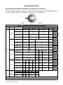
Table 11. Drives, Pulleys, and Belts for Open-Type Motors
HP
Motor
Option
Voltage
Option
Drive (AM/EM)
Option
Motor Pulley
Blower Pulley* Belt**
PN Model
Bore
Size
(Inches)
PN Model
PN
(Length (Feet))
1/4, 1/3 AL2, AL3
AK1, AK2, AK3,
AK5, AK6, AK7
1, 2 4074 1VL34
1/2
111609 AK 99
201809 (3.8)
3, 4
13491 1VL40
5, 6, 7 19111 AK 84
8, 9, 10, 11, 12 18797 AK 64
13, 14, 15, 16, 17 135200 AK 51
1/2, 3/4,
1, 1-1/2
AL4, AL5,
AL6, AL7
AK1, AK2, AK3,
AK5, AK6, AK7
AK8
1, 2 13580 1VL34
5/8
111609 AK 99
3, 4
7962 1VL40
5, 6, 7 19111 AK 84
8, 9, 10, 11, 12 18797 AK 64
13, 14, 15, 16, 17 135200 AK 51
18. 19, 20, 21, 22, 23,24, 25
105476 1VL44
206125 AK 44
26, 27, 28, 29 135201 AK 39
2 AL8
AK1, AK2, AK3,
AK8
1, 2 13580 1VL34
111609 AK 99
3, 4
7962 1VL40
5, 6, 7 19111 AK 84
8, 9, 10, 11, 12 18797 AK 64
13, 14, 15, 16, 17 135200 AK 51
18. 19, 20, 21, 22, 23,24, 25
105476 1VL44
206125 AK 44
26, 27, 28, 29, 30 135201 AK 39
3 AL9 AK2, AK3
9, 10, 11, 12
7962 1VL40
202652 AK124
13, 14, 15, 16, 17, 18, 19 202653 AK94
20, 21, 22, 23, 24, 25, 26 10583 AK69
2 AL8 AK5, AK6, AK7
1, 2 110125 1VP34
7/8
111609 AK 99
3, 4
106748 1VL40
5, 6, 7 19111 AK 84
8, 9, 10, 11, 12 18797 AK 64
13, 14, 15, 16, 17 135200 AK 51
18. 19, 20, 21, 22, 23,24, 25
106758 1VL44
206125 AK44
26, 27, 28, 29, 30 135201 AK39
3, 5 AL9, AL10
AK5, AK6, AK7,
AK8
9, 10, 11, 12
106748 1VL40
101414 BK130
202655 (3.8)
13, 14, 15, 16, 17 202654 BK105
18, 19, 20, 21, 22
37451 1VM50
16153 AK104
201809 (3.8)23, 24, 25, 26, 27, 28, 29 19111 AK84
30, 31, 32, 33, 34, 35, 36 105483 AK69
5 AL10 AK2, AK3
9, 10, 11, 12 7963 2VP42
1-1/8
30621 2AK124 201809 (7.6)
13, 14, 15, 16, 17 111681 1VP50
202652 AK124
201809 (3.8)
18, 19, 20, 21, 22 161444 1VP56
23, 24, 25, 26, 27, 28, 29
111681 1VP50
19111 AK84
30, 31, 32, 33, 34, 35, 36 105483 AK69
*Bore size = 1 inch.
**Assume 17 belt links per foot. Belt PN 201809 is Fenner #0408030. Belt PN 202655 is Fenner #0408050.
BLOWER COMPONENTS—CONTINUED

P-UD&APD (02-20) PN270285R17
19
Table 12. Drives, Pulleys, and Belts for TEFC-Type Motors
HP
Motor
Option
Voltage
Option
Drive (AM)
Option
Motor Pulley
Blower Pulley* Belt**
PN Model
Bore
Size
(Inches)
PN Model
PN
(Length (Feet))
1/3 AL20
AK1, AK2, AK3,
AK5, AK6, AK7
1, 2 4074 1VL34
1/2
111609 AK 99
201809 (3.8)
3, 4
13491 1VL40
5, 6, 7 19111 AK 84
8, 9, 10, 11, 12 18797 AK 64
13, 14, 15, 16, 17 135200 AK 51
1/4 AL19
1, 2 13580 1VL34
5/8
111609 AK 99
3, 4
7962 1VL40
5, 6, 7 19111 AK 84
8, 9, 10, 11, 12 18797 AK 64
13, 14, 15, 16, 17 135200 AK 51
18, 19, 20, 21, 22, 23, 24, 25
105476 1VL44
206125 AK44
26, 27, 28, 29 135201 AK39
1/2, 3/4, 1
AL21,
AL22,
AL23
AK1, AK2, AK3,
AK5, AK6, AK7,
AK8
1, 2 13580 1VL34
111609 AK 99
3, 4
7962 1VL40
5, 6, 7 19111 AK 84
8, 9, 10, 11, 12 18797 AK 64
13, 14, 15, 16, 17 135200 AK 51
1-1/2 AL24
AK1, AK2, AK3,
AK5, AK6, AK7
1, 2 13580 1VL34
111609 AK 99
3, 4
7962 1VL40
5, 6, 7 19111 AK 84
8, 9, 10, 11, 12 18797 AK 64
13, 14, 15, 16, 17 135200 AK 51
18, 19, 20, 21, 22, 23, 24, 25
105476 1VL44
206125 AK44
26, 27, 28, 29 135201 AK39
AK8
1, 2 110125 1VP34
7/8
111609 AK 99
3, 4
106748 1VL40
5, 6, 7 19111 AK 84
8, 9, 10, 11, 12 18797 AK 64
13, 14, 15, 16, 17 135200 AK 51
18, 19, 20, 21, 22, 23, 24, 25
106758 1VL44
206125 AK44
26, 27, 28, 29 135201 AK39
2 AL25
AK5, AK6, AK7,
AK8
1, 2 110125 1VP34
111609 AK 99
3, 4
106748 1VL40
5, 6, 7 19111 AK 84
8, 9, 10, 11, 12 18797 AK 64
13, 14, 15, 16, 17 135200 AK 51
18, 19, 20, 21, 22, 23, 24, 25
106758 1VL44
206125 AK44
26, 27, 28, 29 135201 AK39
3
AL26
AK5, AK6, AK7,
AK8
9, 10, 11, 12
106748 1VL40
7/8
101414 BK130
202655 (3.8)
13, 14, 15, 16, 17 202654 BK105
18, 19, 20, 21, 22
37451 1VM50
16153 AK104
201809 (3.8)23, 24, 25, 26, 27, 28, 29 19111 AK84
30, 31, 32, 33, 34, 35, 36 105483 AK69
AL26 AK1, AK2
9, 10, 11, 12 7963 2VP42
1-1/8
30621 2AK124 201809 (7.6)
13, 14, 15, 16, 17 111681 1VP50
202652 AK124
201809 (3.8)
18, 19, 20, 21, 22 161444 1VP56
23, 24, 25, 26, 27, 28, 29
111681 1VP50
19111 AK84
30, 31, 32, 33, 34, 35, 36 105483 AK69
5 AL27
AK3, AK5, AK6,
AK7, AK8
9, 10, 11, 12 7963 2VP42 30621 2AK124 201809 (7.6)
13, 14, 15, 16, 17 111681 1VP50
202652 AK124
201809 (3.8)
18, 19, 20, 21, 22 161444 1VP56
23, 24, 25, 26, 27, 28, 29
111681 1VP50
19111 AK84
30, 31, 32, 33, 34, 35, 36 105483 AK69
*Bore size = 1 inch.
**Assume 17 belt links per foot. Belt PN 201809 is Fenner #0408030. Belt PN 202655 is Fenner #0408050.

20
P-UD&APD (02-20) PN270285R17
BLOWER COMPONENTS—CONTINUED
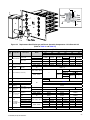
2A 42
UNIT SIZES 030–075 UNIT SIZES 100–125
DIRECT-DRIVE MOTOR ASSEMBLY BELT- DRIVE MOTOR
UNIT SIZES 150–400
2
4
9–19
Figure 7. Blower Backs and Blowers (Refer to Table 13 and Table 14)
Table 13. Blower Backs and Blowers (Unit Sizes 030–125)
HP Item No. Component Description
Unit Size
030 045–075 100 125
PN (Quantity)*
All
1 Restrictor assembly 201408
—
1A Restrictor 194512
1B Angle Restrictor 100892 (3)
1C Screw Sheet metal 195638 (3)
2 Blower assembly 201401
—
2A Blower
9 × 6 82111
10 × 10 — 201770
2B Mounting angle Blower 201740 (2)
—
2C Screw Tek, #10 × 1/2 long 37661 (6)
3 Corner post Blower back
—
196239
4 Back assembly Blower adapter 201403
4A
Adapter back
Bottom 202050 202050
4B Top 196032 196032
4C Left side 197253 197253
4D Right side 197254 197254
4E Screw 195638 (20)
4F
Air baffle
Horizontal 196344 (2)
4G Vertical 196345 196345
4H
Support bracket
Refer to Table 14
4I
4J Bolt
4K Nut
5 Key
6 Blower shaft
7 Blower bearing
1/4–3/4 8 Bracket assembly, motor adjustment
1–5 9–19 Mounting hardware for unit sizes 150–400
*Quantity is one (1) inless otherwise indicated.
NOTE: Items 1, 3, 5, 6, 7, and 8 are not shown in Figure 7.
Page is loading ...
Page is loading ...
Page is loading ...
Page is loading ...
Page is loading ...
Page is loading ...
Page is loading ...
Page is loading ...
Page is loading ...
Page is loading ...
Page is loading ...
Page is loading ...
Page is loading ...
Page is loading ...
Page is loading ...
Page is loading ...
Page is loading ...
Page is loading ...
Page is loading ...
Page is loading ...
Page is loading ...
Page is loading ...
-
 1
1
-
 2
2
-
 3
3
-
 4
4
-
 5
5
-
 6
6
-
 7
7
-
 8
8
-
 9
9
-
 10
10
-
 11
11
-
 12
12
-
 13
13
-
 14
14
-
 15
15
-
 16
16
-
 17
17
-
 18
18
-
 19
19
-
 20
20
-
 21
21
-
 22
22
-
 23
23
-
 24
24
-
 25
25
-
 26
26
-
 27
27
-
 28
28
-
 29
29
-
 30
30
-
 31
31
-
 32
32
-
 33
33
-
 34
34
-
 35
35
-
 36
36
-
 37
37
-
 38
38
-
 39
39
-
 40
40
-
 41
41
-
 42
42


Reznor UDBS User manual
- Type
- User manual
Ask a question and I''ll find the answer in the document
Finding information in a document is now easier with AI
Related papers
-
Reznor UDBP Installation guide
-
Reznor UEAS Installation guide
-
Reznor UDAS Installation guide
-
-
-
-
-
Reznor RDDA Installation guide
-
Reznor APD Installation guide
-
Other documents
-
FMI BTC-8 Operating instructions
-
-
Mammoth APD Installation guide
-
 Adp SEP-250 Installation Instructions Manual
-
-
Unbranded APD Installation guide
-
Thomas & Betts RGM 405 User manual
-
-
 FRU L Shaped Computer Desk Installation guide
-

