Form I-UD&APD Series-HA (1-16), Page 2
IMPORTANT: When the heater is installed, as part of startup, be certain to adjust the valve outlet pressure and
to attach the high altitude adjustment label that is shipped with the heater. Adjustment instructions and derated
input rates and capacities are in the heater installation manual.
Installation
Instructions
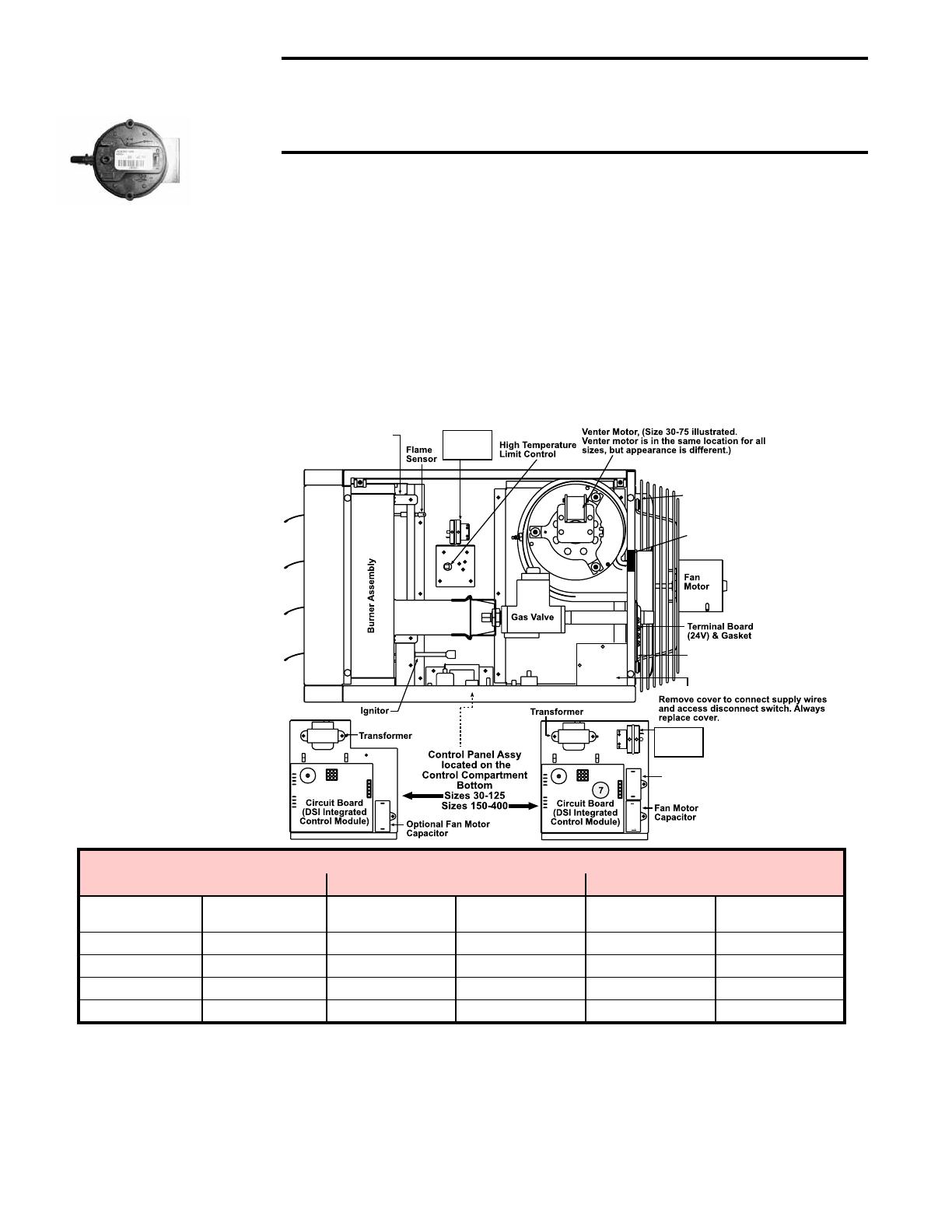
Figure 1
Pressure Switch
Manifold Pressure Settings by Altitude above 6,000 ft (1,830 M)
Altitude Natural Gas (inches w.c.) Propane Gas (Inches w.c.)
Feet Meters
Single & Two Stage
High Fire
Two Stage Low Fire
Single & Two Stage
High Fire
Two Stage Low Fire
6,001 - 7,000 1,831 - 2,135 2.6 1.3 7.4 3.7
7,001 - 8,000 2,136 - 2,440 2.5 1.3 7.1 3.5
8,001 - 9,000 2,441 - 2,745 2.4 1.2 6.7 3.4
9,001 - 10,000 2,746 - 3,045 2.3 1.2 6.7 3.4
WARNING: The instructions in this sheet are designed to prepare
a heater for high altitude operation prior to installation. If your
heater is installed, for your safety, turn off the gas and electric
before servicing.
The high altitude kit is to be selected and installed by a qualied service person
in accordance with these instructions and in compliance with all codes and
requirements of authorities having justication. The qualied agency performing
this work assumes responsibility for this installation.
1. In the control compartment, locate the pressure switch (See FIGURES 1 & 2).
2. Sizes 30 - 125: On the back wall of the control compartment.
Sizes 150 - 400: On the bracket on the bottom of the control compartment.
3. Mark & disconnect the two wires attached to the pressure switch.
4. Locate the two screws holding the switch mounting bracket. Remove the
screws (save screws) and the pressure switch.
5. Using the same screws, install the high altitude pressure switch. Attach the
sensing tube and wires.
Flame Rollout Switch
(Std Power Vent & Separated
Combustion Unit Heaters -
Sizes 30-125)
Pressure
Switch
Sizes 30-125
Pressure
Switch
Sizes 150-400
Venter Motor
Capacitor
Separated Combustion unit
has a collar for combustion
air pipe (not shown)
Interlock Door Switch ONLY
in Separated Combustion
unit
Disconnect Switch ONLY in
Separated Combustion unit
Electric Box - Separated Combustion unit
Figure 2
Pressure Switch Location
(UDAP unit is illustrated)
Pressure switch is in the
same location for all models
Speci
cations & illustrations subject to change without notice and without incurring obligations.
© Nortek Global HVAC, LLC 2016. All rights reserved.
All marks are the property of their respective organizations.
O’Fallon, MO I Printed in U.S.A. (1/16)
D300517 Form I-UD&APD Series-HA (1-16), PN 197081R4

