PENBERTHY MODEL FHS AUTOMATIC LIQUID HEATING SYSTEM
INSTALLATION, OPERATION AND MAINTENANCE INSTRUCTIONS
Emerson.com/FinalControl
Before installation, these instructions must be read carefully and understood.
© 2018 Emerson. All Rights Reserved. VCIOM-04059-EN 19/04
PRODUCT WARRANTY
Emerson warrants its Penberthy products
as designed and manufactured to be free
of defects in the material and workmanship
for a period of one year after the date of
installation or eighteen months after the date
of manufacture, whichever is earliest. Emerson
will, at its option, replace or repair any products
which fail during the warranty period due to
defective material or workmanship.
Prior to submitting any claim for warranty
service, the owner must submit proof of
purchase to Emerson and obtain written
authorization to return the product. Thereafter,
the product shall be returned to Emerson with
freight prepaid.
This warranty shall not apply if the product has
been disassembled, tampered with, repaired
or otherwise altered outside of the Emerson
factory, or if it has been subject to misuse,
neglect or accident.
The responsibility of Emerson hereunder
is limited to repairing or replacing the
product at its expense. Emerson shall not be
liable for loss, damage or expenses
related
directly or indirectly to the installation or use
of its products, or from any other cause or
for consequential damages. It is expressly
understood that Emerson is not responsible
for damage or injury caused to other products,
buildings, personnel or property, by reason of
the installation or use of its products.
This is Emerson's sole warranty and in lieu of
all other warranties, expressed or implied which
are hereby excluded, including in particular all
warranties of merchantability or fitness for a
particular purpose.
This document and the warranty contained
herein may not be modified and no other
warranty, expressed or implied, shall be made
by or on behalf of Emerson unless made in
writing and signed by the company's general
manager or director of engineering.
TABLE OF CONTENTS
Product warranty ................................................ 1
1 About the manual..................................... 2
2 Introduction ............................................. 2
2.1 Features and specifications ........................ 2
2.2 Design ratings at max. and min.
operatingtemperatures .............................. 2
2.3 Application data ........................................... 2
3 Inspection and performance
confirmation ............................................ 2
3.1 Receiving inspection .................................... 2
3.2 User's rating inspection .............................. 2
4 Installation ............................................... 3
4.1 Mounting ....................................................... 3
4.2 Effect of related piping and precautions .... 3
5 Operation ................................................. 3
5.1 Pre-operational check ................................. 3
5.2 Operating ...................................................... 4
5.3 Shutdown ...................................................... 4
6 Maintenance ............................................ 4
6.1 Preventative maintenance ........................... 4
6.2 Maintenance procedures ............................ 4
6.3 Troubleshooting ........................................... 4
7 Disassembly - reassembly ...................... 5
8 Disposal at end of useful life ................... 6
9 Telephone assistance .............................. 6
10 Exploded parts drawing ........................... 7
Tables and figures
Table 1 -
Design ratings
at max. and min.
operatingtemperatures ................... 2
Figure 1 - Installation ......................................... 3
Figure 2 - Reassembly ...................................... 5
Figure 3 - Valve body .......................................... 6
Figure 4 - Exploded parts drawing .................... 7
Figure 5 - Exploded parts drawing (valve) ........ 8

2
PENBERTHY MODEL FHS AUTOMATIC LIQUID HEATING SYSTEM
INSTALLATION, OPERATION AND MAINTENANCE INSTRUCTIONS
2 INTRODUCTION
2.1 Features and specifications
Penberthy model FHS automatic liquid heating
system is a complete, pre-engineered package
including: a steam ring heater, steam inline
check valve, temperature controller, steam flow
control valve, dial thermometer, steam strainer
and associated piping.
The model FHS is designed to maintain a preset
outlet temperature by controlling the amount
of steam condensed into the inlet liquid as it
passes through the steam ring heater.
2.2 Design ratings at maximum and minimum
operating temperatures
1. Steam valve: 150 psig (1.03 MPa) at -20°F
(-29°C) to +370°F (188°C)
2. Heater and wetted parts as stated in Table 1
below.
To determine maximum allowable working
pressure for a specific temperature within the
design limits stated above, the user must refer
to relevant data sheets or, when provided, the
specifically stated design limits on a product
proposal.
TABLE 1 - DESIGN RATINGS AT MAX. AND MIN. OPERATING TEMPERATURES
Material Rating
Bronze
200 psig [1.38 MPa] at -20°F [-29°C] to +150°F [66°C]
125 psig [0.86 MPa] at +400°F [204°C]
316 SS
200 psig [1.38 MPa] at -150°F [-101°C] to +150°F [66°C]
125 psig [0.86 MPa] at +400°F [204°C]
1 ABOUT THE MANUAL
This manual has been prepared as an aid and
guide for personnel involved in installation or
maintenance. All instructions must be read and
understood thoroughly before attempting any
installation, operation or maintenance.
IMPORTANT
Emerson does not have any control over the
manner in which its FHS is handled, installed or
used. Emerson cannot and will not guarantee
that an FHS is suitable for or compatible with the
user's specific application.
WARNING
Always wear safety glasses when installing,
servicing or operating an FHS automatic liquid
heating system. Failure to follow any instruction
could possibly result in a malfunction of the FHS
automatic liquid heating system resulting in
severe physical injury or property damage.
2.3 Application data
The Penberthy FHS is designed to operate
at liquid line pressures from 10 to 100 psig
(70to690 kPaG), steam pressures from 30to
150 psig (205 to 1035 kPaG) and at an air supply
pressure of 18 psig ± 1 psig (125±5kPaG).
Note: For specific application data within the
above ranges, the user should consult the
product proposal for the specific model and
size FHS, or should request the supply of the
applicable technical data sheet.
WARNING
Under no circumstances should these design
ratings or application data be exceeded.
Exceeding design ratings or application data limits
may cause severe physical injury or property
damage.
3 INSPECTION AND PERFORMANCE
CONFIRMATION
3.1 Receiving inspection
Upon receipt of the FHS, check all components
carefully for damage incurred in shipping. If
damage is evident or suspected, do not attempt
installation. Notify the carrier immediately and
request a damage inspection.
3.2 User's rating inspection
The user should confirm that:
1. The FHS size and model, stamped on
the nameplate (163), conforms to the
description on the user's purchase order.
2. The operating conditions described in
the purchase order agree with the actual
operating conditions at the installation site.
3. The actual operating conditions at the
installation site are within the application
data shown on the relevant technical data
sheet or product proposal referred to above.
4. The materials of construction of the FHS are
compatible with both the contained fluid and
the surrounding atmosphere in the specific
application.
IMPORTANT
If the size, model or performance data of the
FHS as received does not conform with any of the
criteria above, do not proceed with installation.
Contact an authorized Penberthy distributor for
assistance.

3
PENBERTHY MODEL FHS AUTOMATIC LIQUID HEATING SYSTEM
INSTALLATION, OPERATION AND MAINTENANCE INSTRUCTIONS
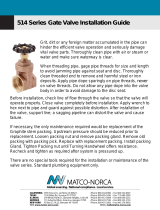
FIGURE 1
Liquid
inlet
Liquid
outlet
Air connection
Steam
inlet
4.2 Effect of related piping and precautions
1. The FHS should be installed with piping and
fittings which provide minimum resistance
to flow. Pipe line friction losses must always
be a consideration when estimating FHS
performance.
2. It is recommended that provisions be made
for pressure gauge connections near the
liquid inlet and outlet, and the steam inlet
connections of the FHS. If performance
problems occur during operation, it may
be necessary to install pressure gauges to
identify the problem.
3. Steam must not have over 20°F (-7°C) of
superheat, or performance will differ from
that published in the relevant technical data
sheet or product proposal referred to above.
4. The steam line must be clean, insulated and
as short as possible to prevent condensation
and line friction losses.
5. Do not impose system piping loads on an
FHS. The unit is designed to be supported
by the liquid inlet and outlet and steam inlet
piping.
6. Provide the steam line with a hand-operated
valve for maintenance and emergency shut-
off. The steam line should be provided with a
steam trap.
7. Provide an air line with an air pressure
regulator capable of maintaining
18 psig (125 kPaG) air pressure. Also, it is
recommended that an air pressure gauge
be installed in this line.
5 OPERATION
5.1 Pre-operational check
1. Ensure that all installation procedures have
been completed.
2. Ensure that any restrictions in the discharge
line have been removed.
3. Ensure that discharge line valves are fully
open.
4. Ensure that the manually operated steam
line valve is fully closed.
5. Ensure that the temperature controller
knob is set to the lowest possible reading
by turning it counterclockwise as far as it
willgo.
6. Ensure that the air pressure regulator valve
is shut off.
Note: When the control valve is completely
installed and connected and ready to be put
into operation, it is necessary for the user to
check for correct travel, freedom of friction,
and correct action (air-to-open) to match the
temperature controller. If adjustments are
necessary, follow all instructions printed in the
installation instruction manual prepared for the
specific actuator by its manufacturer.
4 INSTALLATION
Installation should only be undertaken by
qualified, experienced personnel who are
familiar with this equipment and have read
and understand thoroughly all the instructions
in this manual. The user should refer to the
relevant technical data sheet or product
proposal to obtain dimensional information for
the specific size and model of FHS.
Check Figure 1 for the location of the liquid inlet
and outlet, steam inlet and air inlet connections
to insure correct hook up.
4.1 Mounting
Although the FHS can be oriented in any
position, it is recommended to position the
steam valve actuator horizontally. In this
manner, the thermometer dial will be upright,
the steam piping and steam ring heater will
be in a position to favor removal of condensate
at start up, the steam line strainer will point
downward, and the temperature controller will
be located as recommended by the controller
manufacturer.

4
PENBERTHY MODEL FHS AUTOMATIC LIQUID HEATING SYSTEM
INSTALLATION, OPERATION AND MAINTENANCE INSTRUCTIONS
6 MAINTENANCE
WARNING
Maintenance should only be undertaken by
qualified, experienced personnel who are
familiar with this equipment and have read and
understood thoroughly all the instructions in this
manual.
DO NOT proceed with any maintenance unless the
FHS has been relieved of all pressure or vacuum,
has been allowed to reach ambient temperature
and has been drained or purged of all fluids.
Failure to follow these instructions may cause
severe personal injury or property damage.
5.3 Shutdown
1. Turn the manually operated steam line valve
off in order to first lower the steam line
pressure as much as possible before shut
down.
2. Set the temperature controller knob to
the lowest possible reading by turning it
counterclockwise as far as it will go. This
will cause the steam flow control valve to
close fully.
3. Turn the air pressure regulator valve off
fully.
4. Gradually turn the operating liquid flow off
fully.
WARNING
Failure to maintain the liquid flow throughout
the shutdown procedure may cause live steam
to drive into the liquid piping, resulting in severe
personal injury or property damage.
6.1 Preventative maintenance
The user must create maintenance schedules,
safety manuals and inspection details for each
specific installation of an automatic liquid
heating system.
On all installations, the following items should
be evaluated regularly by the user for purposes
of maintenance:
1. FHS components for corrosion and to
remove debris build up.
2. Piping and fittings for corrosion and to
remove debris build up.
3. All connections to maintain tightness and
eliminate leaks.
4. Air pressure regulator to maintain 18 psig
(125 kPaG).
5. Outlet liquid temperature to maintain
desired setting.
6. Steam line strainer to remove debris
buildup.
7. Temperature controller response and
sensitivity.
The user must determine an appropriate
maintenance schedule necessary for his or her
own specific application upon evaluation of their
operating experience. Realistic maintenance
schedules can only be determined with full
knowledge of the services and application
situation involved.
6.2 Maintenance procedures
1. For servicing the actuator, the user must
follow all steps and precautions printed in
the installation instruction manual prepared
for the specific actuator by its manufacturer.
2. For servicing the steam flow control
valve, the user must follow all steps and
precautions in Section 7.
3. For servicing the steam ring heater, the
user must follow all steps and precautions
printed in the installation manual prepared
for the specific steam ring heater.
4. For servicing the temperature controller,
the user must follow all steps and
precautions printed in the installation
manual prepared for the specific controller
by its manufacturer.
5.2 Operating
1. Turn operating liquid valve fully on and
establish full flow. Keep it on throughout the
entire operation process.
WARNING
Failure to maintain the liquid flow while operating
the FHS with steam can cause live steam to be
driven into the liquid piping, resulting in severe
personal injury or property damage.
2. Turn on the air pressure regulator and
adjust the air pressure knob to 18 psig
(125kPaG).
3. Set the knob of the temperature controller
at 120°F (49°C) and check for proper
operation of the steam valve, which should
be fully open in about 20 seconds time.
Ifthe steam valve does not open in about
20seconds, adjustment of the temperature
controller is necessary. Follow all steps
and precautions printed in the installation
instruction manual prepared for the specific
controller by its manufacturer.
4. Bleed out trapped air inside the pipe
cross where the thermometer is installed
by slightly loosening the thermometer
connection until liquid begins to drip out,
then retighten the thermometer in place.
5. Slowly and partially open the manually
operated steam line valve to first check for
leaks. If leaks are evident, close the valve,
allow the line to cool off, tighten connections
and repeat the procedure until all leaks are
stopped.
6. Turn the temperature controller knob to
100°F (38°C) to allow steam to flow while
checking for leaks. If leaks are evident,
shut off the steam supply, allow the line to
cool off, tighten connections and repeat the
procedure until all leaks are stopped.
7. Fully open the operated steam valve
manually.
8. Turn the temperature controller knob
gradually to the desired outlet liquid
temperature and allow the FHS to
stabilize. Compare the knob setting with
the thermometer reading and adjust if
necessary.
There are two distinct operating noise levels
typical of the FHS, within specific operating
conditions. For detailed information on these
operating conditions, request Emerson to
supply the relevant technical data sheet.
6.3 Troubleshooting (see Table 2)
TABLE 2 - TROUBLESHOOTING
Problem Cause Solution
Surges in liquid flow. Pumping action. Increase pressure discharge.
Surges in outlet temperature. Temperature controller overshoot. Desensitize controller. Refer to temperature
controller installation manual.

5
7 DISASSEMBLY - REASSEMBLY
WARNING
Do not proceed with removal of the FHS from
connecting piping unless the FHS has been
relieved of all pressure or vacuum, has been
allowed to reach ambient temperature and has
been drained or purged of all fluids. Failure
to follow these instructions may cause severe
personal injury.
1. Preparation
Secure a workbench sufficiently sized to lay
out parts as they are removed.
2. Removal of valve sub-assembly from the FHS
may be accomplished as follows:
a. Loosen and remove the air line connection
(60) from the valve actuator.
b. Connect the air hose to the air connection of
the actuator (239) and pressurize (0-12 psig,
0-85 kPaG) to open the valve 20-80%.
c. Loosen the stem connector nut (4) and stem
packing nut (26).
d. Unscrew the valve stem (17) from the
diaphragm actuator stem connector,
turning counterclockwise to remove.
e. Remove the valve position indicating disc
(43) from the stem.
f. Loosen the yoke nut (4B) and remove from
the valve bonnet (20).
g. Remove the actuator diaphragm from the
valve (75).
h. Reduce the air pressure in the actuator to
0psig and remove the air line.
i. Remove the valve from connecting piping.
j. Place the valve on a work bench, inlet side
down, with the stem pointing up.
k. While holding the valve body firmly, loosen
and remove the four (4) cap screws (100),
and free the bonnet from the body (11) of the
valve.
l. Grasp the valve piston (217) at the lower
end and slide the stem downward out of the
bonnet carefully.
FIGURE 2
Threads to
diaphragm
actuator rod
Valve
packing
Steam
pressure
Stem
(pistonend)
PENBERTHY MODEL FHS AUTOMATIC LIQUID HEATING SYSTEM
INSTALLATION, OPERATION AND MAINTENANCE INSTRUCTIONS
IMPORTANT
When sliding the stem out of the bonnet, care
must be taken to avoid damaging the packing
assembly with the threads of the valve stem.
m. Using a stiff wire with a short hook on its
end, remove all gaskets (7, 7A, 7B, 7C) cage
(29) and seat (16) from inside body.
Note: It may be required to lightly tap the
side of the body with a hammer to loosen and
remove the seat.
n. Discard all removed gaskets. Do not re-use
gaskets under any circumstances.
WARNING
Gaskets are deformed permanently by
compression and, if re-used, can cause leaks
resulting in release of live steam causing severe
personal injury or property damage.
o. Inspect the valve seat and piston for wear or
damage and replace if necessary.
3. Packing box maintenance must be performed
as follows:
IMPORTANT
The valve stem must be out of the bonnet before
attempting to remove the packing so that the
stem is not damaged accidentally. If the packing
is not to be replaced be careful when moving the
valve stem through the packing, so that the stem
threads do not damage the packing.
a. Remove the packing nut (26) and packing
gland (19) from the bonnet (20).
b. Using a stiff wire with a short hook on its
end, draw the packing rings (211) out of the
bonnet.
4. Reassembly procedures for replacing stem
packing.
a. Slide the valve stem through the packing
box of the bonnet.
b. Carefully slide a full set of new packing
rings over the valve stem (see Figure2)
making sure that the packing is not
damaged by the threads of the stem.
c. Replace the packing gland and packing nut
and tighten finger tight.
IMPORTANT
The stem packing nut should only be screwed
down finger tight. When necessary to compress
the packing more, tighten the packing nut by hand
again.

6
8 DISPOSAL AT END OF USEFUL LIFE
Penberthy FHS' are used in a variety of fluid
applications. By following the appropriate
federal and industry regulations, the user
must determine the extent of preparation
and treatment the FHS must incur before its
disposal. A Material Safety Data Sheet (MSDS)
may be required before disposal services accept
certain components.
Metal, glass and polymers should be recycled
whenever possible. Refer to order and relevant
data sheet for materials of construction.
5. Reassembly of valve sub-assembly.
a. Assemble the components as shown in
Figure 5 and per instructions below.
b. With the valve body resting on a work bench,
inlet side down, insert the seat gasket and
seat inside body making certain that the
seat is properly seated.
c. Insert the cage over the top ring of the seat.
d. Place the two (2) gaskets over the top ring of
the cage in proper order.
e. Insert the bonnet/body gasket into the body.
f. Make certain that the stem is properly
installed in the bonnet (refer to Section 4 -
Installation) and replace the bonnet into the
body.
g. Hold the valve firmly and replace the cap
screws through the bonnet and wrench
tighten.
h. Replace the valve body into the piping
system using a PTFE tape or equivalent on
all male tapered pipe threads as shown in
Figure 3.
i. Connect air hose and regulator to
diaphragm actuator and pressurize to fully
open valve (100%).
j. Place the actuator yoke over the threads of
the valve bonnet, making sure to place the
yoke nut and valve position indicating disc
over the stem while doing this.
k. Thread the valve stem into the actuator
connector rod approximately 6 full turns.
l. Tighten the yoke nut down finger tight and
check to see if the yoke is seated against the
valve bonnet.
m. If the yoke is not seated against the valve
bonnet, thread the valve stem further into
the actuator connector rod until the yoke
is seated against the valve bonnet, then
tighten the yoke nut in place.
n. Tighten the stem connector nut against the
valve position disc and actuator connector
rod.
o. Slowly reduce the air pressure to the
actuator to close the valve. At 0psig
(0kPaG), the valve position indication disc
should indicate that the valve is closed. If
the disc goes below the 0% open mark on
the actuator scale, this indicates improper
adjustment.
p. To adjust the disc position, increase the
air pressure to the actuator to raise the
valve 20-40% open. Then loosen the stem
connector nut a few turns and turn the stem
counterclockwise one turn, tighten the stem
connector nut and release the air pressure.
This procedure should be repeated until the
indicating disc is exactly indicating 0% open
for the valve.
q. Remove the air hose from actuator
r. Reconnect the air line connection to the
actuator.
s. Refer to Section 5 - Operation, when
returning the FHS to service.
FIGURE 3
PENBERTHY MODEL FHS AUTOMATIC LIQUID HEATING SYSTEM
INSTALLATION, OPERATION AND MAINTENANCE INSTRUCTIONS
9 TELEPHONE ASSISTANCE
If you are having difficulty with your FHS,
contact your local Penberthy distributor. So that
we may assist you more effectively, please have
as much of the following information available
as possible when you call:
- Model number
- Name of the company from whom you
purchased the FHS
- Invoice number and date
- Process conditions (pressure, flow rates, tank
shape, etc.)
- A brief description of the problem
- Trouble shooting procedures that failed
If attempts to solve your problem fail, you may
request to return your
FHS
to the factory for
intensive testing. You must obtain a Return
Authorization (R.A.) number from Emerson
before returning anything. Failure to do so will
result in the unit being returned to you without
being tested, freight collect. To obtain an R.A.
number, the following information (in addition to
that above) is needed:
- Reason for return
- Person to contact at your company
- 'Ship-to' address
There is a minimum charge for evaluation
of non-warranty units. You will be contacted
before any repairs are initiated should the cost
exceed the minimum charge. If you return a
unit under warranty, but it is not defective, the
minimum charge will apply.
Tape
Direction
of wrap
1-2
threads

7
239
4B
43
4
75
79
76
79
99
79
75A
79
4A
79A
60
91
148
65
171
206
137
73
100
63
10 EXPLODED PARTS DRAWING
FIGURE 4
PARTS LIST
Ref. nr Item
4 Nut
4A Nut
4B Nut jet
43 Disc
60 Fitting
63 Cross
65 Controller
73 Bracket
75 Valve
75A Valve
76 Strainer
79 Nipple
79A Nipple
91 Thermometer
99 Union
100 Screw
137 Bolt
148 Bushing
171 Tubing
206 Elbow
239 Actuator
Steam ring
heater
PENBERTHY MODEL FHS AUTOMATIC LIQUID HEATING SYSTEM
INSTALLATION, OPERATION AND MAINTENANCE INSTRUCTIONS

8
17
4
7C
7B
217
7A
16
29
7
100A
163
20
11
211
100
26
19
Neither Emerson, Emerson Automation Solutions, nor any of their affiliated entities assumes responsibility for the selection, use or maintenance of any product.
Responsibility for proper selection, use, and maintenance of any product remains solely with the purchaser and end user.
Penberthy is a mark owned by one of the companies in the Emerson Automation Solutions business unit of Emerson Electric Co. Emerson Automation Solutions,
Emerson andthe Emerson logo are trademarks and service marks of Emerson Electric Co. All other marks are the property of their respective owners.
The contents of this publication are presented for informational purposes only, and while every effort has been made to ensure their accuracy, they are not to be
construed as warranties or guarantees, express or implied, regarding the products or services described herein or their use or applicability. All sales are governed by
our terms and conditions, which are available upon request. We reserve the right to modify or improve the designs or specifications of such products at any time without
notice.
Emerson.com/FinalControl
PENBERTHY MODEL FHS AUTOMATIC LIQUID HEATING SYSTEM
INSTALLATION, OPERATION AND MAINTENANCE INSTRUCTIONS
FIGURE 5
Valve (75)
PARTS LIST
Ref. nr Item
4 Nut
7 Gasket
7A Gasket
7B Gasket
7C Gasket
11 Body
16 Seat
17 Stem
19 Gland
20 Bonnet
26 Nut, stem packing
29 Cage
100 Screw
100A Screw
163 Nameplate
211 Packing
217 Piston
/