
Frymaster, a member of the Commercial Food Equipment Service Association, recommends using
CFESA Certified Technicians.
24-Hour Service Hotline 1-800-551-8633
AUGUST 2006
www.frymaster.com E-mail: [email protected]
*8196150*
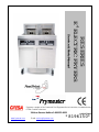
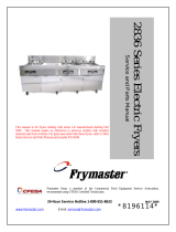
RE SERIES
E
4
ELECTRIC FRYERS
Service & Parts Manual

i
NOTICE
IF, DURING THE WARRANTY PERIOD, THE CUSTOMER USES A PART FOR THIS ENODIS
EQUIPMENT OTHER THAN AN UNMODIFIED NEW OR RECYCLED PART PURCHASED DIRECTLY
FROM FRYMASTER DEAN, OR ANY OF ITS AUTHORIZED SERVICE CENTERS, AND/OR THE
PART BEING USED IS MODIFIED FROM ITS ORIGINAL CONFIGURATION, THIS WARRANTY WILL
BE VOID. FURTHER, FRYMASTER DEAN AND ITS AFFILIATES WILL NOT BE LIABLE FOR ANY
CLAIMS, DAMAGES OR EXPENSES INCURRED BY THE CUSTOMER WHICH ARISE DIRECTLY OR
INDIRECTLY, IN WHOLE OR IN PART, DUE TO THE INSTALLATION OF ANY MODIFIED PART
AND/OR PART RECEIVED FROM AN UNAUTHORIZED SERVICE CENTER.
DANGER
Copper wire suitable for at least 167°F (75°C) must be used for power connections.
DANGER
The electrical power supply for this appliance must be the same as indicated on the rating and
serial number plate located on the inside of the fryer door.
DANGER
This appliance must be connected to the voltage and phase as specified on the rating and serial
number plate located on the inside of the fryer door.
DANGER
All wiring connections for this appliance must be made in accordance with the wiring diagrams
furnished with the equipment. Wiring diagrams are located on the inside of the fryer door.
DANGER
Do not store or use gasoline or other flammable vapors and liquids in the vicinity of this or any
other appliance.
WARNING
Do not attach accessories to this fryer unless fryer is secured from tipping. Personal injury may
result.
WARNING
Frymaster fryers equipped with legs are for permanent installations. Fryers fitted with legs
must be lifted during movement to avoid damage and possible bodily injury. For a moveable or
portable installation, Frymaster optional equipment casters must be used.
Questions? Call 1-800-551-8633 or email at [email protected].
WARNING
Do not use water jets to clean this equipment.
WARNING
This equipment is intended for indoor use only. Do not install or operate this equipment in
outdoor areas.

ii
DANGER
Adequate means must be provided to limit the movement of this appliance without depending
on or transmitting stress to the electrical conduit. A restraint kit is provided with the fryer. If
the restraint kit is missing contact your local Frymaster Factory Authorized Service Center
(FASC) for part number 826-0900.
DANGER
Prior to movement, testing, maintenance and any repair on your Frymaster fryer, disconnect all
electrical power from the fryer.
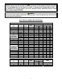
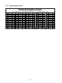
ELECTRICAL POWER SPECIFICATIONS
Three (3) Phase Requirements
MINIMUM SIZE AMPS PER LEG
kW VOLTAGE PHASE
WIRE
SERVICE
AWG mm
2
L1 L2 L3
14 208 3 3 6 16 39 39 39
14 240 3 3 6 16 34 34 34
14 480 3 3 8 10 17 17 17
14 220/380 3 4 6 16 21 21 21
14 240/415 3 4 6 16 20 20 21
14 230/400 3 4 6 16 21 21 21
208 3 3 6 16 39 39 39
240 3 3 6 16 34 34 34
220/380 3 4 6 16 21 21 21
ALL
EPRI 14kW
(SOLID STATE)
240/415 3 4 6 16 20 20 20
17 208 3 3 6 16 48 48 48
17 240 3 3 6 16 41 41 41
17 480 3 3 6 16 21 21 21
17 220/380 3 4 6 16 26 26 26
17 240/415 3 4 6 16 24 24 24
17 230/400 3 4 6 16 25 25 25
208 3 3 6 16 48 48 48
240 3 3 6 16 41 41 41
220/380 3 4 6 16 26 26 26
ALL
EPRI 17kW
(SOLID STATE)
240/415 3 4 6 16 24 24 24
22 208 3 3 4 25 61 61 61
22 240 3 3 4 25 53 53 53
22 480 3 3 6 16 27 27 27
22 220/380 3 4 6 16 34 34 34
22 240/415 3 4 6 16 31 31 31
22 230/400 3 4 6 16 32 32 32
Single Phase Requirements
MINIMUM SIZE
kW VOLTAGE PHASE
WIRE
SERVICE
AWG mm
2
AMPS
14 208 1 2 3 34 68
14 240 1 2 4 25 59
14 480 1 2 8 10 30

iii
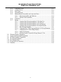
RE SERIES E
4
ELECTRIC FRYERS
TABLE OF CONTENTS
CAUTIONARY STATEMENTS........................................................................................................ i
ELECTRICAL POWER SPECIFICATIONS................................................................................. ii
CHAPTER 1: Service Procedures
1.1 General ..............................................................................................................................1-1
1.2 Replacing a Controller.......................................................................................................1-1
1.3 Replacing Component Box Components..........................................................................1-1
1.4 Replacing a High-Limit Thermostat..................................................................................1-3
1.5 Replacing a Temperature Probe........................................................................................1-3
1.6 Replacing a Heating Element............................................................................................1-5
1.7 Replacing Contactor Box Components.............................................................................1-6
1.8 Replacing a Frypot ............................................................................................................1-7
1.9 Built-In Filtration System Service Procedures..................................................................1-9
1.9.1 Filtration System Problem Resolution ...............................................................1-9
1.9.2 Replacing the Filter Motor, Filter Pump and Related Components.................1-10
1.9.3 Replacing the Filter Transformer or Filter Relay.............................................1-12
1.10 Basket Lift Service Procedures .......................................................................................1-12
1.11 Interface Board Diagnostic Chart....................................................................................1-15
1.12 Probe Resistance Chart....................................................................................................1-16
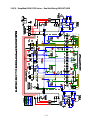
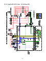
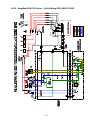
1.13 Wiring Diagrams.............................................................................................................1-17
1.13.1.1 Basket Lift Wiring 208-250V...........................................................................1-17
1.13.1.2 Basket Lift Wiring 100-120V...........................................................................1-18
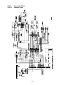
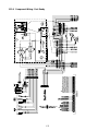
1.13.2.1 Component Wiring Standard............................................................................1-19
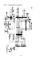
1.13.2.2 Component Wiring Fryer and Half ..................................................................1-20
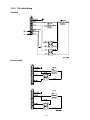
1.13.3 Tilt Switch Wiring............................................................................................1-21
1.13.4 Component Wiring – Fast Ready..................................................................... 1-22
1.13.5 Fast Ready Computer Wiring...........................................................................1-23
1.13.6 Contactor Box-Delta Configuration................................................................. 1-24
1.13.7 Contactor Box-WYE Configuration.................................................................1-25
1.13.8 Terminal Block Wiring ....................................................................................1-26
1.13.9 Oil Disposal Wiring..........................................................................................1-27
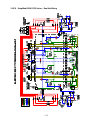
1.13.10 Simplified RE14/17/22 Full-Vat Delta Wiring................................................1-28
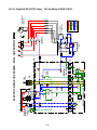
1.13.11 Simplified RE14/17/22 Dual-Vat Delta Wiring...............................................1-29
1.13.12 Simplified RE14/17/22 Full-Vat Export WYE Wiring....................................1-30
1.13.13 Simplified RE14/17/22 Dual-Vat Export WYE Wiring...................................1-31
1.13.14 Simplified RE14/17/22 Full-Vat EPRI Wiring................................................1-32
1.13.15 Simplified RE14/17/22 Full-Vat EPRI Export WYE Wiring..........................1-33
CHAPTER 2: Parts List
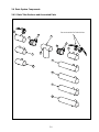
2.1 Accessories........................................................................................................................2-1
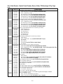
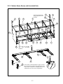
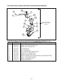
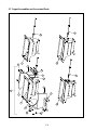
2.2 Basket Lift Assembly and Associated Parts......................................................................2-2
2.3 Cabinetry...........................................................................................................................2-4
2.3.1 Backs, Control Panel Frames, Doors, Sides, Tilt Housings and Top Caps........2-4
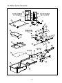
2.3.2 Cabinet Bases, Braces and Associated Parts......................................................2-7
2.4 Drain System Components................................................................................................2-9
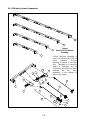
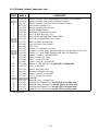
2.4.1 Drain Tube Sections and Associated Parts.........................................................2-9
2.4.2 Drain Valves and Associated Parts (Units with Built-In Filtration) ................2-11
2.4.3 Drain Valves and Associated Parts (Units without Built-In Filtration) ...........2-15
2.5 Electronics and Electrical Components...........................................................................2-16

iv
RE SERIES E
4
ELECTRIC FRYERS
TABLE OF CONTENTS cont.
2.5.1 Component Boxes ............................................................................................2-16
2.5.2 Contactor Boxes............................................................................................... 2-18
2.5.3 Fuse Boxes .......................................................................................................2-22
2.5.4 Terminal Blocks............................................................................................... 2-23
2.5.5 Heating Element Assemblies and Associated Parts.........................................2-24
2.5.5.1 Element Assemblies and Hardware.................................................. 2-24
2.5.5.2 Element Tube Assemblies................................................................2-26
2.5.6 Controllers........................................................................................................2-27
2.5.7 Wiring............................................................................................................... 2-28
2.5.7.1 Contactor Box Wiring Assemblies 12-Pin Dual Vat........................2-28
2.5.7.2 Contactor Box Wiring Assemblies 12-Pin Full Vat.........................2-29
2.5.7.3 Contactor Box Wiring Assemblies 6-Pin Left Element...................2-30
2.5.7.4 Contactor Box Wiring Assemblies 9-Pin Right Element.................2-30
2.5.7.5 Main Wiring Harnesses.................................................................... 2-31
2.5.7.6 Component Box, Filter Pump and Basket Lift Wiring Harnesses ...2-33
2.5.7.7 Component Box to Filter Pump Harness..........................................2-34
2.5.7.8 Basket Lift Harness.......................................................................... 2-34
2.5.7.9 Interface Board to Controller Wiring Harness 15-Pin......................2-34
2.6 Filtration System Components........................................................................................ 2-35
2.7 Frypots and Associated Components..............................................................................2-38
2.8 Oil Return System Components......................................................................................2-40
2.9 Oil Disposal Plumbing ....................................................................................................2-42
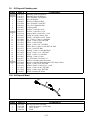
2.10 Oil Disposal Wand ..........................................................................................................2-43
2.11 Wiring and Pin Connectors .............................................................................................2-44
2.12 Fasteners..........................................................................................................................2-45

1-1
RE SERIES E
4
ELECTRIC FRYERS
CHAPTER 1: SERVICE PROCEDURES
1.1 General
Before performing any maintenance on your Frymaster fryer, disconnect the fryer from the electrical
power supply.
When electrical wires are disconnected, it is recommended that they be marked in such a way as to
facilitate re-assembly.
1.2 Replacing a Controller
1. Disconnect the fryer from the electrical power supply.
2. The controller bezel is held in place by tabs at the top and bottom. Slide the metal bezel up to
disengage the lower tabs. Then slide the bezel down to disengage the upper tabs.
3. Remove the two screws from the upper corners of the control panel. The control panel is hinged
at the bottom and swings open from the top.
4. Unplug the wiring harness from the connector on the back of the controller and disconnect the
grounding wire from terminal adjacent to the connector. Remove the control panel assembly by
lifting it from the hinged slots in the control panel frame.
5. Remove the controller from the control panel assembly and install the replacement controller.
Reinstall the control panel assembly by reversing steps 1 and 2.
1.3 Replacing Component Box Components
1. Disconnect the fryer from the electrical power supply.
2. The controller bezel is held in place by tabs at the top and bottom. Slide the metal bezel up to
disengage the lower tabs. Then slide the bezel down to disengage the upper tabs.
Ground Wire Terminal
15-Pin Connecto
r

1-2
3. Remove the two screws from the upper corners of the control panel and allow the control panel
to swing down.
4. Unplug the wiring harness from the 15-pin connector on the interface board and disconnect the
grounding wire from terminal adjacent to the 15-pin connector on the back of the controller.
Remove the control panel assembly by lifting it from the hinge slots in the control panel frame.
5. Disconnect the wiring from the component to be replaced, being sure to make a note of where
each wire was connected.
6. Dismount the component to be replaced and install the new component, being sure that any
required spacers, insulation, washers, etc. are in place.
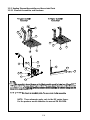
NOTE: If more room to work is required, the control panel frame assembly may be removed by
removing the hex head screws that secure it to the fryer cabinet (see illustration below). If this
option is chosen, all control panel assemblies must be removed per steps 1 and 2 above. The
cover plate on the lower front of the component box may also be removed if desired. Removing
the component box itself from the fryer is not recommended due to the difficulty involved in
disconnecting and reconnecting the oil-return valve rods, which pass through openings in the
component box.
Remove these three
screws at each end.
Remove these two screws
from the center supports.
Removing the Control Panel Frame and Top Cap Assembly
7. Reconnect the wiring disconnected in Step 3, referring to your notes and the wiring diagrams on
the fryer door to ensure that the connections are properly made. Also, verify that no other wiring
was disconnected accidentally during the replacement process.
8. Reverse steps 1 through 4 to complete the replacement and return the fryer to service.

1-3
1.4 Replacing a High-Limit Thermostat
1. Remove the filter pan and lid from the unit. Drain the frypots into a Shortening Disposal Unit
(SDU) or other appropriate metal container.
DANGER
DO NOT drain more than one full frypot or two split frypots into the SDU at one time.
2. Disconnect the fryer from the electrical power supply and reposition it to gain access to the rear
of the fryer.
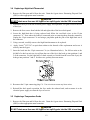
3. Remove the four screws from both the left and right sides of the lower back panel.
4. Locate the high-limit that is being replaced and follow the two-black wires to the 12-pin
connector C-6. Note where the leads are connected prior to removing them from the connector.
Unplug the 12-pin connector C-6 and using a pin-pusher push the pins of the high-limit out of
the connector.
5. Using a wrench, carefully unscrew the high-limit thermostat to be replaced.
6. Apply Loctite
™
PST 567 or equivalent sealant to the threads of the replacement and screw it
securely into the frypot.
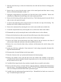
7. Insert the leads into the 12-pin connector C-6 (see illustration below). For full-vat units or the
left half of a dual-vat unit (as viewed from the rear of the fryer) the leads go into positions 1 and
2 of the connector. For the right half of a dual-vat unit (as viewed from the rear of the fryer), the
leads go into positions 7 and 8. In either case, polarity does not matter.
8. Reconnect the 12-pin connecting plug C-6. Use wire ties to secure any loose wires.
9. Reinstall the back panels reposition the fryer under the exhaust hood, and reconnect it to the
electrical power supply to return the fryer to service.
1.5 Replacing a Temperature Probe
1. Remove the filter pan and lid from the unit. Drain the frypots into a Shortening Disposal Unit
(SDU) or other appropriate metal container.
DANGER
DO NOT drain more than one full frypot or two split frypots into the SDU at one time.

1-4
2. Disconnect the fryer from the electrical power supply and reposition it to gain access to the rear
of the fryer.
3. Remove the four screws from both sides of the lower back panel. Then remove the two screws
on both the left and right sides of the back of the tilt housing. Lift the tilt housing straight up to
remove from the fryer.
4. Locate the red and white wires of the temperature probe to be replaced. Note where the leads
are connected prior to removing them from the connector. Unplug the 12-pin connector C-6 and
using a pin-pusher push the pins of the temperature probe out of the connector.
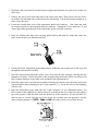
5. Raise the element and remove the securing probe bracket and metal tie wraps that secure the
probe to the element (see illustration below).
6. Gently pull on the temperature probe and grommet, pulling the wires up the rear of the fryer and
through the element tube assembly.
7. Insert the replacement temperature probe (wires first) into the tube assembly ensuring that the
grommet is in place. Secure the probe to the elements using the bracket which was removed in
Step 5 and the metal tie wraps which were included in the replacement kit.
8. Route the probe wires out of the tube assembly following the element wires down the back of the
fryer through the Heyco bushings to the 12-pin connector C-6. Secure the wires to the sheathing
with wire ties.
9. Insert the temperature probe leads into the 12-pin connector C-6 (see illustration below). For
full-vat units or the right half of a dual-vat unit (as viewed from the rear of the fryer) the red lead
goes into position 3 and the white lead into position 4 of the connector. For the left half of a
dual-vat unit (as viewed from the rear of the fryer), the red lead goes into position 9 and the
white lead into position 10. NOTE: Right and left refer to the fryer as viewed from the rear.

1-5
10. Secure any loose wires with wire ties making sure that the lead wires will not interfere with the
movement of the springs. Rotate the elements up and down making sure that movement is not
restricted and that the wires are not pinched.
11. Reinstall the tilt housing and back panels, reposition the fryer under the exhaust hood, and
reconnect it to the electrical power supply to return the fryer to service.
1.6 Replacing a Heating Element
1. Perform steps 1-3 of section 1.5, Replacing a Temperature Probe.
2. On dual-vat fryers, and on full-vat fryers where the temperature probe is attached to the element
being replaced, disconnect the wire harness containing the probe wiring. Using a pin pusher,
disconnect the probe wires from the 12-pin connector C-6.
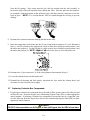
3. In the rear of the fryer directly behind the frypot disconnect the 6-pin connector for the left
element (as viewed from the front of the fryer) or the 9-pin connector for the right element.
Press in on the tabs on each side of the connector while pulling outward on the free end to extend
the connector and release the element leads (see photo below). Pull the leads out of the
connector and out of the wire sleeving.
4. Raise the element to the full up position and support the elements.
5. Remove the hex head screws and nuts that secure the element to the tube assembly and pull the
element out of the frypot. NOTE: Full-vat elements consist of two dual-vat elements clamped
together. For full-vat units, remove the element clamps before removing the nuts and screws that
secure the element to the tube assembly.
6. If applicable, recover the probe bracket and probe from the element being replaced and install
them on the replacement element. Install the replacement element in the frypot, securing it with
the nuts and screws removed in Step 5 to the tube assembly. Ensure the gasket is between the
tube and element assembly.
7. Route the element leads through the element tube assembly and into the wire sleeving to prevent
chafing. Ensure that the wire sleeving is routed back through the Heyco bushing keeping it clear

1-6
from the lift springs. Also ensure that the wire sleeving extends into the tube assembly to
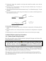
prevent the edge of the tube assembly from chafing the wires. Press the pins into the connector
in accordance with the diagram on the following page, and then close the connector to lock the
leads in place. NOTE: It is critical that the wires be routed through the sleeving to prevent
chafing.
1
4
2
5
3
6
1
4
2
5
3
6
789
5
R
4R
6
R
1R
2
R
3R
Index Marker marks
Position 1
5L 4L6L 1L2L3L
8. Reconnect the element connector ensuring that the latches lock.
9. Insert the temperature probe leads into the 12-pin wiring harness connector C-6 (see illustration
below). For full-vat units or the right half of a dual-vat unit, the red lead goes into position 3 and
the white into position 4. For the left half of a dual-vat unit, the red lead goes into position 9 and
the white into position 10. NOTE: Right and left refer to the fryer as viewed from the rear.
10. Reconnect the 12-pin connector C-6 of the wiring harness disconnected in Step 2.
11. Lower the element down onto the basket rack.
12. Reinstall the tilt housing and back panels, reposition the fryer under the exhaust hood, and
reconnect it to the electrical power supply.
1.7 Replacing Contactor Box Components
1. If replacing a contactor box component above the built-in filter system, remove the filter pan and
lid from the unit. Drain the frypots into a Shortening Disposal Unit (SDU) or other appropriate
metal container. If replacing a contactor box component in a non-filter unit or a frypot that’s not
over the filter pan, drain the frypot above the box into a Shortening Disposal Unit (SDU) or other
appropriate metal container.
DANGER
DO NOT drain more than one full frypot or two split frypots into the SDU at one time.

1-7
2. Disconnect the fryer from the electrical power supply.
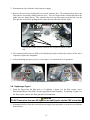
3. Remove the two screws securing the cover of the contactor box. The contactor boxes above the
filter pan are accessed by sliding under the fryer. They are located to the left and right above the
guide rails (see photo below). The contactor boxes of non-filter units or frypots not over the
filter pan are accessed by opening the fryer door directly under the affected frypot.
4. The contactors and relays are held on by threaded pin studs so that only removal of the nut is
required to replace the component.
5. After performing necessary service, reverse steps 1-4 to return the fryer to operation.
Left and right views of mechanical contactor box components.
1.8 Replacing a Frypot
1. Drain the frypot into the filter pan or, if replacing a frypot over the filter system, into a
Shortening Disposal Unit (SDU) or other appropriate metal container. If replacing a frypot over
the filter system, remove the filter pan and lid from the unit.
DANGER
DO NOT drain more than one full frypot or two split frypots into the SDU at one time.
2. Disconnect the fryer from the electrical power supply and reposition it to gain access to both the
front and rear.
Remove two screws to access contactor box components above the filter
pan
.

1-8
3. Slide the metal bezel up to release the bottom tabs, then slide the bezel down to disengage the
upper tabs.
4. Remove the two screws from the upper corners of the control panels and allow them to swing
down (see illustration and photo on page 1-1).
5. Unplug the wiring harnesses and ground wires from the backs of the controllers. Remove the
controllers by lifting them from the hinge slots in the control panel frame.
6. Remove the tilt housing and back panels from the fryer. The tilt housing must be removed first in
order to remove the upper back panel.
7. To remove the tilt housing remove the hex head screws from the rear edge of the housing. The
housing can be lifted straight up and off the fryer.
8. Remove the control panel by removing the screw in the center and the nuts on both sides.
9. Loosen the component boxes by removing the screws, which secure them in the cabinet.
10. Dismount the top cap by removing the nuts at each end that secure it to the cabinetry.
11. Remove the hex head screw that secures the front of the frypot to the cabinet cross brace.
12. Remove the top-connecting strip that covers the joint with the adjacent frypot.
13. Unscrew the Teflon vent/vacuum-breaker tube fitting, unscrew the nut located on the front of
each section of drain tube, and remove the tube assembly from the fryer.
14. Remove the covers from the drain safety switch(es) and disconnect the switch wiring at the
switch(es).
15. At the rear of the fryer, unplug the 12-pin connector C-6 and, using a pin pusher, disconnect the
high-limit thermostat leads.
16. Disconnect the oil return flexline(s) at the frypot end(s).
17. Raise the elements to the “up” position and disconnect the element springs.
18. Remove the machine screws and nuts that secure the element tube assembly to the frypot.
Carefully lift the element assembly from the frypot and secure it to the cross brace on the rear of
the fryer with wire ties or tape.
19. Carefully lift the frypot from the fryer and place it upside down on a stable work surface.
20. Recover the drain valve(s), oil return flexline connection fitting(s), and high-limit thermostat(s)
from the frypot. Clean threads and apply Loctite
™
PST 567 or equivalent sealant to the threads
of the recovered parts and install them in the replacement frypot.
21. Carefully lower the replacement frypot into the fryer. Reinstall the hex head screw removed in
step 7 to attach the frypot to the fryer.

1-9
22. Position the element tube assembly in the frypot and reinstall the machine screws and nuts
removed in step 14.
23. Reconnect the oil return flexlines to the frypot, and replace aluminum tape, if necessary, to
secure heater strips to the flexlines.
24. Insert the high-limit thermostat leads disconnected in step 13 (see illustration on page 1-3 for pin
positions).
25. Reconnect the drain safety switch wiring to the switch(es) in accordance with the diagram below
then reinstall the switch covers.
RIGHT
DRAIN SAFETY SWITCH
LEFT
DRAIN SAFETY SWITCH
(DUAL-VAT ONLY)
ORANGE Pin 15 J4
BLUE Pin 1 C6
ORANGE Pin 7 J4
BLUE Pin 7 C6
26. Reinstall the drain tube assembly.
27. Reinstall the top connecting strips, top cap, control panel, component box, tilt housing and back
panels.
28. Reinstall controllers in the control panel frame and reconnect the wiring harnesses and ground
wires.
29. Reposition the fryer under the exhaust hood and reconnect it to the electrical power supply.
1.9 Built-in Filtration System Service Procedures
1.9.1 Filtration System Problem Resolution
One of the most common causes of filtration problems is placing the filter paper on the bottom of the
filter pan rather than over the filter screen.
CAUTION
Ensure that filter screen is in place prior to filter paper placement and filter pump
operation. Improper screen placement is the primary cause of filtration system
malfunction.
Whenever the complaint is “the pump is running, but no oil is being filtered,” check the installation
of the filter paper, and ensure that the correct size is being used. While you are checking the filter
paper, verify that the O-rings on the pick-up tube of the filter pan are in good condition. Missing or
worn O-rings allow the pump to take in air and decrease its efficiency.
If the pump motor overheats, the thermal overload will trip and the motor will not start until it is
reset. If the pump motor does not start, press the red reset switch (button) located on the rear of the
motor at the front of the fryer.

1-10
If the pump starts after resetting the thermal overload switch, then something is causing the motor to
overheat. A major cause of overheating is when several frypots are filtered sequentially, overheating
the pump and motor. Allow the pump motor to cool at least 30 minutes before resuming operation.
Pump overheating can be caused by:
• Solidified shortening in the pan or
filter lines, or
• Attempting to filter unheated oil
(cold oil is more viscous,
overloading the pump motor and
causing it to overheat).
If the motor runs but the pump does not
return oil, there is a blockage in the pump.
Incorrectly sized or installed paper/pads will
allow food particles and sediment to pass
through the filter pan and into the pump.
When sediment enters the pump, the gears
bind, causing the motor to overload, again
tripping the thermal overload. Shortening
that has solidified in the pump will also
cause it to seize, with the same result.
A pump seized by debris or hard shortening
can usually be freed by manually moving
the gears with a screwdriver or other
instrument.
Disconnect power to the filter system, remove the input plumbing from the pump, and use a
screwdriver to manually turn the gears.
● Turning the pump gears in reverse will release a hard particle.
● Turning the pump gears forward will push softer objects and solid shortening through the
pump and allow free movement of the gears.
Incorrectly sized or installed paper/pads will also allow food particles and sediment to pass through
and clog the suction tube on the bottom of the filter pan. Particles large enough to block the suction
tube may indicate that the crumb tray is not being used. Pan blockage can also occur if shortening is
left in the pan and allowed to solidify. Blockage removal can be accomplished by forcing the item
out with an auger or drain snake. Compressed air or other pressurized gases should not be used to
force out the blockage.
1.9.2 Replacing the Filter Motor, Filter Pump, and Related Components
1. Remove the filter pan and lid from the unit. Drain the frypots into a Shortening Disposal Unit
(SDU) or other appropriate metal container.
Sediment Particle
Oil Flow
Up for reverse
Down for forward
Sediment Particle

1-11
DANGER
DO NOT drain more than one full frypot or two split frypots into the SDU at one time.
2. Disconnect the fryer from the electrical power supply and reposition it to gain access to both the
front and rear.
3. Disconnect the two flexlines running to the oil-return manifold at the rear of the fryer as well as
the pump suction flexline at the end of the filter pan connection (see photo below).
Disconnect flexlines indicated by the arrows.
4. Loosen the nut and bolt that secures the bridge to the oil-return manifold.
5. Remove the cover plate from the front of the motor and disconnect the motor wires.
6. Unplug the pump motor assembly 6-pin connector C-2 and, using a pin pusher, disconnect the
vent vacuum-breaker solenoid (pins 2 and 5) that is attached to the oil return manifold.
7. Remove the two nuts and bolts that secure the front of the bridge to the cross brace and carefully
slide the bridge rearward off the cross brace until its front end can be lowered to the floor. Undo
the single nut holding it in place in back. Be careful not to let the rear of the bridge slip off the
manifold at this point.
8. Get a good grip on the bridge, carefully pull it forward off the oil-return manifold, and lower the
entire assembly to the floor. Once on the floor, pull the assembly out the front of the fryer.
9. When required service has been completed, reverse steps 6-12 to reinstall the bridge. NOTE:
The black motor wires go on the top terminal, the white on the bottom. The pump solenoid valve
wires go in positions 1 and 4 of the 6-pin connector C-2; the vent vacuum-breaker solenoid valve
wires go in positions 2 and 5; the red/black heater tape wires go into position 3 and the
violet/white wires go into position 6 (see illustration on the following page).

1-12
10. Reconnect the unit to the electrical power supply, and verify that the pump is functioning
correctly (i.e., when a filter handle is placed in the ON position, the motor should start and there
should be strong suction at the intake fitting and outflow at the rear flush port.)
11. When proper operation has been verified, reinstall the back panels and the filter pan and lid.
12. Reposition the fryer under the exhaust hood and reconnect it to the electrical power supply to
return the fryer to service.
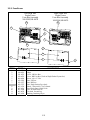
1.9.3 Replacing the Filter Transformer or Filter Relay
Disconnect the fryer from the electrical power supply. Remove the left controller from the fryer to
expose the interior of the left component box. The filter transformer and relay are located as shown
in the illustration below. NOTE: The right component box is identical to the left except that the
filter transformer and relay are not present. The components are held on by threaded pin studs so
that only removal of the nut is required to replace the component.
Filter
Relay
Filter
Transformer
Dual-vat configuration illustrated. In full-vat units, left filter handle is not present.
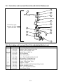
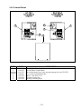
1.10 Basket Lift Service Procedures
RE Series electric fryers may be equipped with automatic basket lifts. Basket lifts always come in
pairs, although each operates independently.
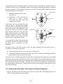
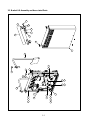
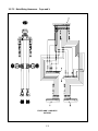
A modular basket lift (illustrated on the following page) is a self-contained sub-assembly
consisting of a pair of toothed rods which support removable basket lift arms, a pair of reversible-
drive gear motors, and four microswitches. The gear motors engage the teeth of the rods, moving
them up or down depending upon the motors’ direction of rotation. The microswitches at the upper
and lower limits of movement stop the motors when the basket is in the full up or full down position.

1-13
100-120V Configuration
208-250V Configuration
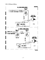
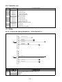
Timing circuitry in the controller initiates and stops basket lift operation depending upon the
variables programmed by the operator. When the product button is pressed, the timing circuitry
activates a coil in the basket lift relay to supply power to the lower microswitch. The microswitches
stop the motor at the lift’s upper and lower travel limits and reverse the direction of current flow thus
reversing the motor direction.
When the product button is pushed on the computer/controller, current flows through a coil in the
basket lift relay, causing the lower circuit to be activated. The basket lift lowers, closing the
normally open upper-micro-switch. When the downward-moving rod opens the lower normally
closed microswitch, the power to the motor ceases to flow. When the computer/controller times out,
the current to the relay coil is cut, allowing the upper circuit to be activated. The basket lift then
raises and re-closes the lower microswitch. When the basket lift rod clears the upper microswitch,
the microswitch reopens, power to the circuit is cut, and the motor stops. Pushing the product button
restarts the cycle.
Problems with the basket lift can be grouped into three categories:
● Binding/jamming problems
● Motor and gear problems
● Electronic problems
BINDING/JAMMING PROBLEMS
Noisy, jerky or erratic movement of the lifts is usually due to lack of lubrication of the rods and their
bushings. Apply a light coat of Lubriplate
®
or similar lightweight white grease to the rod and
bushings to correct the problem.
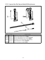
With the modular basket lift, another possible cause of binding is improper positioning of the motor,
which prevents the gear from correctly engaging the teeth in the rod. To correct the problem, loosen
the screws that hold the motor in place and move it forward or backward until the rod has just
enough slack to be rotated slightly.

1-14
MOTOR AND GEAR PROBLEMS
With the modular basket lift, the most likely problem to be encountered in this category is erratic
motion of the lift due to a worn drive gear. Failure to keep the lift rod and bushings properly
lubricated will cause unnecessary wear of the gear. The problem is corrected by replacing the worn
gear.
If the lift cycles correctly but fails to remain in the up position (i.e., goes up, but then slowly settles
back down into the frypot), the problem is a failed motor brake. A failed motor brake cannot be
repaired and requires replacement of the motor itself.
If power is reaching the motor but the motor fails to run, the motor is burned out and must be
replaced.
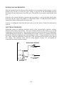
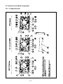
ELECTRONIC PROBLEMS
Within this category are problems associated with the relays, microswitches, capacitors, resistors,
interface board, wiring, and controls. The most common problem in this category is a lift that
continuously travels up and down. This is usually caused by a microswitch that is out of adjustment.
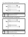
Troubleshooting the electronics of a modular basket lift is simply a process of verifying current flow
through the individual components up to and including the motor. Using a multimeter set to the 250
VAC range, check the connections on both sides of the component for the presence of the applied
line voltage. The schematic below and the wiring diagram on page 1-16 can identify the
components and wiring connection points.

1-15
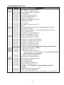
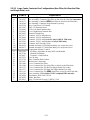
1.11 Interface Board Diagnostic Chart
The following diagram and charts provide ten quick system checks that can be performed using only
a multimeter.
Meter Setting Test Pin Pin Results
12 VAC Power 50 VAC Scale 3 of J2 1 of J2 12-16 VAC
24 VAC Power 50 VAC Scale 2 of J2 Chassis 24-30 VAC
*Probe Resistance (RH) R X 1000 OHMS 11 of J2 10 of J2 See Chart
*Probe Resistance (LH) R X 1000 OHMS 1 of J1 2 of J1 See Chart
High-Limit Continuity (RH) R X 1 OHMS 9 of J2 6 of J2 0 - OHMS
High-Limit Continuity (LH) R X 1 OHMS 6 of J1 9 of J1 0 - OHMS
Latch Contactor Coil (RH) R X 1 OHMS 8 of J2 Chassis 3-10 OHMS
Latch Contactor Coil (LH) R X 1 OHMS 5 of J1 Chassis 3-10 OHMS
Heat Contactor Coil (RH) R X 1 OHMS 7 of J2 Chassis 11-15 OHMS
Heat Contactor Coil (LH) R X 1 OHMS 4 of J1 Chassis 11-15 OHMS
* Disconnect 15-Pin harness from the computer/controller before testing the probe circuit.
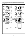
Diagnostic LED Legend
CMP indicates power from 12V transformer
24 indicates power from 24V transformer
HI (RH) indicates output (closed) from right latch
relay
HI (LH) indicates output (closed) from left latch
relay
HT (RH) indicates output from right heat relay
HT (LH) indicates output from left heat relay
AL (RH) indicates output (open) from right latch
relay
AL (LH) indicates output (open) from left latch
relay
NOTE – When testing the test points on J1
and J2 test use the illustration above dis-
regarding any silk-screened numbers on
the board depicting the location of Pin 1.
Pin 1 is located in the bottom right corner of
Both J1 and J2. These test points are ONLY
for RE Series boards with J1 and J2 plugs on
the front of the board.
PN 106-6664
Page is loading ...
Page is loading ...
Page is loading ...
Page is loading ...
Page is loading ...
Page is loading ...
Page is loading ...
Page is loading ...
Page is loading ...
Page is loading ...
Page is loading ...
Page is loading ...
Page is loading ...
Page is loading ...
Page is loading ...
Page is loading ...
Page is loading ...
Page is loading ...
Page is loading ...
Page is loading ...
Page is loading ...
Page is loading ...
Page is loading ...
Page is loading ...
Page is loading ...
Page is loading ...
Page is loading ...
Page is loading ...
Page is loading ...
Page is loading ...
Page is loading ...
Page is loading ...
Page is loading ...
Page is loading ...
Page is loading ...
Page is loading ...
Page is loading ...
Page is loading ...
Page is loading ...
Page is loading ...
Page is loading ...
Page is loading ...
Page is loading ...
Page is loading ...
Page is loading ...
Page is loading ...
Page is loading ...
Page is loading ...
Page is loading ...
Page is loading ...
Page is loading ...
Page is loading ...
Page is loading ...
Page is loading ...
Page is loading ...
Page is loading ...
Page is loading ...
Page is loading ...
Page is loading ...
Page is loading ...
Page is loading ...
Page is loading ...
Page is loading ...
Page is loading ...
-
 1
1
-
 2
2
-
 3
3
-
 4
4
-
 5
5
-
 6
6
-
 7
7
-
 8
8
-
 9
9
-
 10
10
-
 11
11
-
 12
12
-
 13
13
-
 14
14
-
 15
15
-
 16
16
-
 17
17
-
 18
18
-
 19
19
-
 20
20
-
 21
21
-
 22
22
-
 23
23
-
 24
24
-
 25
25
-
 26
26
-
 27
27
-
 28
28
-
 29
29
-
 30
30
-
 31
31
-
 32
32
-
 33
33
-
 34
34
-
 35
35
-
 36
36
-
 37
37
-
 38
38
-
 39
39
-
 40
40
-
 41
41
-
 42
42
-
 43
43
-
 44
44
-
 45
45
-
 46
46
-
 47
47
-
 48
48
-
 49
49
-
 50
50
-
 51
51
-
 52
52
-
 53
53
-
 54
54
-
 55
55
-
 56
56
-
 57
57
-
 58
58
-
 59
59
-
 60
60
-
 61
61
-
 62
62
-
 63
63
-
 64
64
-
 65
65
-
 66
66
-
 67
67
-
 68
68
-
 69
69
-
 70
70
-
 71
71
-
 72
72
-
 73
73
-
 74
74
-
 75
75
-
 76
76
-
 77
77
-
 78
78
-
 79
79
-
 80
80
-
 81
81
-
 82
82
-
 83
83
-
 84
84


Frymaster RE14 User manual
- Category
- Deep fryers
- Type
- User manual
Ask a question and I''ll find the answer in the document
Finding information in a document is now easier with AI
Related papers
-
 Frymaster e4 User manual
-
 Frymaster 8196428 User manual
-
 Frymaster 2836 User manual
-
 Frymaster 2836 Series Electric Fryers User manual
-
 Frymaster 2836 User manual
-
 Frymaster FP236 User manual
-
 Frymaster FP236 User manual
-
 Frymaster BIRE14 User manual
-
 Frymaster 8196203 User manual
-
Frymaster RE80 User manual


Other documents
-
SPT 30209 Operating instructions
-
 DV8 OFFROAD TTJK-01 Installation guide
-
Bennett Marine ES2000 User manual
-
GE ZBD7005G01II Installation guide
-
JONARD TOOLS MF-5-25 Operating instructions
-
Scotsman Changing the Control Board from its Original Configuration to the AutoSentry System - 17-2813-01 Operating instructions
-
ESAB 60 AMP Troubleshooting instruction
-
 T & S Brass & Bronze Works BL-4705-02 Datasheet
-
 T & S Brass & Bronze Works BL-4705-01 Datasheet
-
Weatherables AWCP-LVNEPTUNEKIT-4 Installation guide


