Page is loading ...

IT
Istruzioni ed avvertenze per l’installatore
EN
Instructions and warnings for the installer
DE
Anweisungen und Hinweise für den Installateur
FR
Instructions et consignes pour l’installateur
ES
Instrucciones y advertencias para el instalador
PT
Instruções e advertências para o instalador
H70/200AC
centrale di comando per 2 motori asincroni
Istruzioni originali
IS43 Rev08 11/02/2019

5
M
LN
M
1614 15 17 18 19 20 21 22 23 24
41 40 39 38 37 36 35 34 33 32 31 30 29 28 27 26 25
PROG TEST
+
-
COM
AP1
CM
CH1
AP2
CM
CH2
COR
LAM
ANT
+5V
ENC1
ENC2
COM
FCA1
FCC1
FCA2
FCC2
COM
COM
FCC2
FCC1
FCA2
FCA1
COM
ENC2
ENC1
ANT
COM
CORAP1L N PE CH1CM CH2CMAP2 LAM
+5V
ES
ST
COM
COS1
COS2
FT1
FT2
COM
SC
COM
24V~
COM
PED
PP
CH
AP
ORO
COM
F1
FUSE
F6,3A
F6,3A
F2
FUSE
F630mA
F630mA
H93/RX22A/I
RICEVITORE RADIO
RADIO RECEIVER
N
CONDENSATORE
CAPACITOR
CONDENSATORE
CAPACITOR
230Vac
L
PR1PR2
MOTORE 2
MOTOR 2
MOTORE 1
MOTOR 1
verde (o nero) / green (or black)
blu / blue
rosso / red
rosso / red
blu / blue
verde (o nero) / green (or black)
1

6
2
3
41
46
47
40 39 38 37 36 35 34 33 32 31 30 29 28 27 26 25
PROG TEST
+
-
ST
COM
COS1
COS2
FT1
FT2
COM
SC
COM
COM
PED
PP
CH
AP
ORO
COM
+24
ES
ST
COM
COS1
COS2
FT1
FT2
COM
SC
COM
24V~
COM
PED
PP
CH
AP
ORO
COM
Orologio / Timer
Apertura parziale / Partial opening
Passo passo / Step by step
Chiusura / Closing
Apertura / Opening
Spia cancello aperto /
Open gate light 24 Vac 3W
STOP
Bordo sensibile 1 / Safety edge 1
Bordo sensibile 2 / Safety edge 2
41
46
47
40
ES
ST
COM
Elettroserratura
Electric lock
FUSE T2A
H70/EL
F1
F2
N
230 Vac
L
FUSE T1A
8
10 9
7
245631
12 Vac
16 VA

7
4
*
Per le impostazioni delle fotocellule, consultare il relativo manuale di installazione.
For photocell settings, refer to the relevant installation manual.
41 40 39 38 37 36 35 34 33 32
ST
ST
COM
COM
COS1
COS2
FT1
FT2
COM
SC
COM
24V
COS1
COS2
FT1
FT2
COM
SC
COM
24V~
RXTX
P1
12 12345
24V
COM
COM
24V
FT1
*
41 40 39 38 37 36 35 34 33 32 31 30 29
2
ST
COM
COS1
COS2
FT1
FT2
COM
SC
COM
24V~
COM
PED
PP
CH
RXTX
P1
RXTX
12 12345
12 12345
24V
COM
COM
24V
FT1
24V
COM
COM
COM
24V
FT2
ST
COM
COS1
COS2
FT1
FT2
COM
SC
COM
24V
COM
PED
PP
*
COLLEGAMENTO CON 1 COPPIA FOTOCELLULE • CONNECTION WITH 1 PAIR OF PHOCELLS
COLLEGAMENTO CON 2 COPPIE FOTOCELLULE • CONNECTION WITH 2 PAIRS OF PHOCELLS
FOTOCELLULE · PHOTOCELLS
USO RACCOMANDATO per fotocellule Serie F2ES - F2S
RECOMMENDED USE for Series F2ES - F2S photocells
USO RACCOMANDATO per fotocellule
Serie F2ES - F2S
RECOMMENDED USE for Series F2ES -
F2S photocells

8
TEST FOTOCELLULE · PHOTOCELLS TEST ($ )
COLLEGAMENTO CON 1 COPPIA FOTOCELLULE • CONNECTION WITH 1 PAIR OF PHOCELLS
COLLEGAMENTO CON 2 COPPIE FOTOCELLULE • CONNECTION WITH 2 PAIRS OF PHOCELLS
*
Per le impostazioni delle fotocellule, consultare il relativo manuale di installazione.
For photocell settings, refer to the relevant installation manual.
5
41 40 39 38 37 36 35 34 33 32
ST
COM
COS1
COS2
FT1
FT2
COM
SC
COM
24V~
RXTX
12 12345
SCSC
COM
COM
24V24V
24VFT1
ST
COM
COS1
COS2
FT1
FT2
COM
SC
COM
24V
*
41 40 39 38 37 36 35 34 33 32 31 30 29 28 27
ST
COM
COS1
COS2
FT1
FT2
COM
SC
COM
24V~
COM
PED
PP
CH
AP
RXTX
12 12345
TX
12
RX
12345
COM
COM
COM
COM
FT2
COM
24V24V
24V24V
24VFT1
SC
SC
ST
COM
COS1
COS2
FT1
FT2
COM
SC
COM
24V
COM
PED
PP
CH
AP
*
USO RACCOMANDATO per
fotocellule Serie F2ES - F2S
RECOMMENDED USE for Series
F2ES - F2S photocells
USO RACCOMANDATO per fotocellule Serie F2ES - F2S
RECOMMENDED USE for Series F2ES - F2S photocells

9
N
L
Luce di cortesia
Courtesy light
FUSIBILE / FUSE max 1A
N
L
Lampeggiante
Flashing light
FUSIBILE / FUSE T500mA
Marrone/Brown
Marrone/Brown
Marrone/Brown
Marrone/Brown Blu/Blue
Blu/Blue
230 Vac FIXING LIGHT
230V 40W max
230V 100W
COR
LAM
COR
LAM
6
LAMPEGGIANTE · FLASHING LIGHT
R92/LED230
FIFTHY/230
1614 15 17 18 19 20
COM
COR
LAM
ANT
+5V
ENC1
ENC2
COM
230Vac
ANT
N
L
FUSIBILE / FUSE T500mA
Marrone/Brown
Marrone/Brown Blu/Blue
RG58 max 10 m

10
1614 15 17 18 19 20 21 22 23 24
COM
ANT
+5V
ENC1
ENC2
COM
FCA1
FCC1
FCA2
FCC2
COM
COM
FCC2
FCA2
FCC1
FCA1
COM
ENC2
ENC1
+5V
ANT
COM
Rosso/RedRosso/Red
Antenna
RG58 max 10 m
ENCODER2 ENCODER1
Finecorsa chiusura anta 2
Closing limit switch leaf 2
Finecorsa apertura anta 2
Opening limit switch leaf 2
Finecorsa chiusura anta 1
Closing limit switch leaf 1
Finecorsa apertura anta 1
Opening limit switch leaf 1
Marrone/BrownMarrone/Brown
Blu/BlueBlu/Blue
Rosso/RedRosso/Red
Marrone/BrownMarrone/Brown
Blu/BlueBlu/Blue
7501
con ENCODER OTTICO · with OPTICAL ENCODER
7

11
1614 15 17 18 19 20 21 22 23 24
COM
ANT
+5V
ENC1
ENC2
COM
FCA1
FCC1
FCA2
FCC2
COM
Antenna
RG58 max 10 m
ENCODER2 ENCODER1
Finecorsa chiusura anta 2
Closing limit switch leaf 2
Finecorsa apertura anta 2
Opening limit switch leaf 2
Finecorsa chiusura anta 1
Closing limit switch leaf 1
Finecorsa apertura anta 1
Opening limit switch leaf 1
COM
FCC2
FCA2
FCC1
FCA1
COM
ENC2
ENC1
+5V
ANT
COM
7502
Blu/Blue
Blu/BlueBianco/White
Marrone/BrownMarrone/Brown
Blu/Blue
Blu/BlueBianco/White
Marrone/BrownMarrone/Brown
con ENCODER MAGNETICO · with MAGNETIC ENCODER
E30/800
8

12
con ENCODER MAGNETICO · with MAGNETIC ENCODER
SERIE R21
dalla versione V.1
R21 SERIES
from version V.1
16 17 18 19 20 21 22 23 24
+5V
ENC1
ENC2
COM
FCA1
FCC1
FCA2
FCC2
COM
COM
FCC2
FCA2
FCC1
FCA1
COM
ENC2
ENC1
+5V
Marrone/Brown
Blu/BlueGrigio/Grey
Blu/BlueGrigio/Grey
Marrone/Brown
ENCODER1ENCODER2
Nero/Black
Nero/Black
7503
CENTRALE DI COMANDO
CONTROL PANEL
9

17
IT
4 Caratteristiche tecniche prodotto
H70/200AC
TENSIONE DI ALIMENTAZIONE 230 V
± 10% 50 Hz
POTENZA MASSIMA ASSORBITA DA RETE 1400 W
FUSIBILI
F1 = F6,3A 250 V (5x20) protezione circuito potenza motori
F2 = F630mA 250 V (5x20) protezione alimentazione accessori
MOTORI COLLEGABILI 2
ALIMENTAZIONE MOTORE 230 V
TIPOLOGIA MOTORE asincrono monofase
TIPOLOGIA CONTROLLO MOTORE regolazione di fase con triac
POTENZA MASSIMA PER MOTORE 600 W
POTENZA MASSIMA LAMPEGGIANTE 40 W 230 V
- 25 W 24 V / (contatto puro)
POTENZA MASSIMA LUCE DI CORTESIA 100 W 230 V
- 25 W 24 V / (contatto puro)
POTENZA MASSIMA ELETTROSERRATURA 25 W (contatto puro) max. 230 V
POTENZA LUCE CANCELLO APERTO 3 W (24 V )
POTENZA USCITA ACCESSORI 9 W
TEMPERATURA DI FUNZIONAMENTO
-20°C +55°C
GRADO DI PROTEZIONE IP44
PRESSIONE SONORA DURANTE L'USO <70 dB (A)
DIMENSIONI PRODOTTO dimensioni in mm 137x156x43 Peso: 0,72 kg

EN
45
1 General safety precautions
WARNING: IMPORTANT SAFETY INSTRUCTIONS
THESE INSTRUCTIONS MUST BE FOLLOWED TO GUARANTEE THE SAFETY
OF THE PERSONS
PRESERVE THESE INSTRUCTIONS
This installation manual is intended for qualified personnel only.
Failure to observe the information included in this manual may result in
personal injury or damage to the equipment.
ROGER TECHNOLOGY cannot be held responsible for any damage or injury due to
improper use or any use other than the intended usage indicated in this manual.
The installation, electrical connections and adjustments must be performed by
qualified personnel, in accordance with best practices and in compliance with
applicable regulations.
Read the instructions carefully before installing the product.
Incorrect installation may pose risks.
Before installing the product, make sure it is in perfect condition: In case of doubts,
do not use the product and refer exclusively to professionally qualified personnel.
Do not install the product in explosive environment and atmosphere: inflammable
gas or vapours constitute serious danger for safety.
Before installing the motor, make all structural modifications related to the safety
precautions and to the protection or segregation of areas involving crushing,
shearing, dragging risks or any other risks.
WARNING: check that the existing structure fulfils the required resistance and
stability specifications.
ROGER TECHNOLOGY is not liable for failure to observe the good practices in the
construction of fixtures to be motorised or for deformations that may occur during
use.
The safety devices (photocells, sensing edges, emergency stops, etc.) must be
installed taking into consideration the following: the regulations and directives in
force, the good practices criteria, the installation environment, the operating logic
of the system and the forces generated by the motorised door or gate.
The safety devices must protect any areas where there is crushing, shearing,
dragging or any other danger in general generated by the motorised door or gate;
the installer is advised to check that the moving wings do not have sharp edges or
anything that may pose shearing and/or dragging risks.
If it is deemed necessary based on the risk analysis, install sensing edges on the
mobile part.
It should be noted that, as provided by the UNI EN 12635 standard, all requirements
of the EN 12604 and EN 12453 standards must be fulfilled and, if necessary, also
checked.
The European standards EN 12453 and EN 12445 define the minimum safety

EN
46
requirements for the operation of automatic doors and gates. In particular, these
standards require the use of force limiting and safety devices (sensing ground
plates, photocell barriers, hold-to-run operation, etc.) intended to detect persons or
objects in the operating area and prevent collisions in all circumstances.
The installer is required to measure impact forces and select on the control unit the
appropriate speed and torque values to ensure that the door or gate remains within
the limits defined by the standards EN 12453 and EN 12445.
ROGER TECHNOLOGY cannot be held responsible for any damage or injury caused
by the installation of incompatible components which compromise the safety and
correct operation of the device.
If the hold-to-run function is active, the installer will have the obligation to check
the maximum stop distance or the alternative use of the rubber deformable edge,
the closing speed or the gate and in general all aspects indicated by the applicable
regulations. Moreover, please not that if the command means is fixed, it must be
located in a position guaranteeing the automation system control and operation and
the command type and the use type must comply with the UNI EN 12453 standard,
prospectus 1 (with the following restrictions: type A or B command or type 1 or 2
use).
In case of hold-to-run operation, remove any potential persons away from the range
of action of the automation system's moving parts; the direct commands must be
installed at a minimum height of 1.5 m and must not be accessible to the public;
moreover, unless the device is key operated, they must be located with a direct view
to the motorised part and far from the moving parts.
Apply the signs indicated by the regulations in force for the identification of the
dangerous areas.
Each installed device must have a visible indication of the motorised door or
gate identification data, in accordance with the EN 13241-1:2001 standard or
subsequent revisions
A switch or an omnipolar cut-off switch with a contact opening of at least 3
mm must be installed on the mains power line; put the cut-off switch in OFF
position and disconnect any buffer batteries before performing any cleaning or
maintenance operations.
Ensure that an adequate residual current circuit breaker with a 0.03 A threshold
and a suitable overcurrent cut-out are installed upstream the electrical installation
in accordance with best practices and in compliance with applicable legislation.
When requested, connect the automation to an effective earthing system that
complies with current safety standards.
The electronic parts must be handled using anti-static conductive wrist straps with
grounding wire.
Only use original spare parts when repairing or replacing products.
The installer must provide the user with complete instruction for using the motorised
door or gate in automatic, manual and emergency modes, and must hand the
operating instructions to the user of the installation upon completion.
Keep away from hinges and moving parts.
Keep out of the area of action of the motorised door or gate while it is moving.

EN
47
Never try to stop the motorised door or gate while it is moving as this may be
dangerous.
The motorised door or gate may be used by children aged 8 and above, by persons
with diminished physical, sensory or mental capacity and by persons without the
necessary experience and knowledge provided that they are supervised or have
received adequate instruction on using the device safely and to ensure that they
understand the dangers involved in its operation.
Children must be supervised at all times to ensure that they do not play with the
device and that they keep out of the area of action of the motorised door or gate.
Keep remote controls and any other control devices out of the reach of children to
prevent the risk of the motorised door or gate being operated unintentionally.
Failure to observe these instructions may lead to danger.
Any repair or technical interventions must be performed by qualified personnel.
The cleaning and maintenance operations must be performed exclusively by
qualified personnel.
In the event of a fault or malfunction of the product, turn the main power switch off
and have the installation serviced by qualified personnel and refrain from attempting
to repair or perform any direct intervention yourself.
The packaging materials (plastic, polystyrene, etc.) should not be discarded in the
environment or left within reach of children, as they are a potential source of danger.
Dispose of and recycle the packaging items according to the provisions of the laws
in force.
These instructions must be kept and must be made available to any other persons
authorised to use the installation.
Declaration of Conformity
The undersigned Dino Florian, legal representative of Roger Technology - Via Botticelli 8, 31021 Mogliano V.to (TV)
DECLARES that the H70/200AC digital control unit is compliant with the provisions established by Community directives:
– 2006/95/CE LVD Standard
– 2004/108/CE EMC Standard
– 2011/65/CE RoHS Standard
and that all the standards and/or technical requirements indicated as follows have been applied:
EN 61000-6-3
EN 61000-6-2
EN 60335-1
EN 60335-2-103
Last two figures of year in which marking was applied | 09.
Place: Mogliano V.to Date: 02-07-2009 Signature

EN
48
2 Symbols
The symbols and their meaning in the manual or on the product label are indicated
below.
Generic danger.
Important safety information. Indicates operations and situations in
which the personnel involved must pay close attention.
Dangerous voltage risk.
Indicates operations and situations in which the personnel involved
must pay close attention to dangerous voltages.
Hot surfaces risk.
Indicates danger due to hot surfaces or which anyway have high
temperatures (risk of burns)
Useful information
Indicates useful information for the installation.
Refer to the Installation and use instructions.
Indicates the obligation to refer to the manual or original document,
which must be available for future use and must not be damaged in
any way.
Protective earth connection point.
Indicates the admissible temperature range.
Alternating current (AC)
Direct current (DC)
Symbol for the product disposal according to the WEEE directive, see
chapter 21.
3 Product description
The H70/200AC control unit is intended to control gate automation systems with 1 or 2 asynchronous single phase 230 V
AC ROGER motors.
Use the same type of motor for both gate leaves in automation installations for double leaf swing gates.
ROGER TECHNOLOGY cannot be held responsible for any damage or injury due to improper use or
any use other than the intended usage indicated in this manual.
Adjust the opening and closure speed, deceleration and delay settings appropriately for the specific installation, ensuring that
the gate leaves overlap correctly.
For further information, refer to the installation manual of the motor.

EN
49
4 Technical characteristics of product
H70/200AC
MAINS POWER VOLTAGE 230 V
± 10% 50 Hz
MAXIMUM MAINS POWER ABSORPTION 1400 W
FUSES F1 = F6,3A 250 V (5x20) motor power circuit protection
F2 = F630mA 250 V (5x20) accessories power supply protection
CONNECTABLE MOTORS 2
MOTOR POWER SUPPLY 230 V
MOTOR TYPE single-phase asynchronous
MOTOR CONTROL TYPE triac phase control
MAXIMUM MOTOR POWER 600 W
MAXIMUM POWER, FLASHING LIGHT 40 W 230 V
- 25 W 24 V / (potential free contact)
MAXIMUM POWER COURTESY LIGHT 100 W 230 V
- 25 W 24 V / (potential free contact)
ELECTRIC LOCK POWER 25 W (potential free contact) max. 230 V
GATE OPEN LIGHT POWER 3 W (24 V )
MAXIMUM ACCESSORY CURRENT AB-
SORPTION
9 W
OPERATING TEMPERATURE
-20°C +55°C
DEGREE OF PROTECTION IP44
SOUND PRESSURE DURING USE <70 dB(A)
PRODUCT DIMENSION dimensions in mm 137x156x43 Weight: 0,72 kg

EN
50
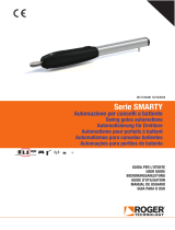
5 Description of connections
Figures 1-2-3-4 show connection diagrams.
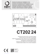
5.1 Typical installation
1
8
9
2
3
5
5
4
4
6
7
Recommended cable
1 Power supply H07RN-F 3x1,5 mm2 double insulated cable
2 Connection Motor1 to control panel Cable 4x1,5 mm
2
3 Connection Motor2 to control panel Cable 4x1,5 mm
2
Encoder connection Cable 3x0,5 mm
2
(max 30 m)
4
Photocell - Receiver
Cable 4x0,5 mm
2
(max 20 m)
5
Photocell - Transmitter
Cable 2x0,5 mm
2
(max 20 m)
6
Key selector R85/60 Cable 3x0,5 mm
2
(max 20 m)
Keypad H85/TTD - H85/TDS (connecting to control panel to decoder
board H85/DEC - H85/DEC2)
Cable 3x0,5 mm
2
(max 20 m)
7
Flashing light R92/LED230 - FIFTHY/230
Power supply 230Vac - LED
Cable 2x1 mm
2
(max 10 m)
Antenna Cable tipo RG58 (max 10 m)
8
Gate open indicator
Cable 2x0,5 mm
2
(max 20 m)
9
Courtesy light
Cable 2x1 mm
2
(max 20 m)
SUGGESTIONS: with existing installations, we recommend checking the cross section of the cables and that the
cables themselves are in good condition.

EN
51
5.2 Electrical connections
A switch or an omnipolar cut-off switch with a contact opening of at least 3 mm must be installed
on the mains power line; put the cut-off switch in OFF position and disconnect any buffer batteries
before performing any cleaning or maintenance operations.
Ensure that an adequate residual current circuit breaker with a 0.03 A threshold and a suitable
overcurrent cut-out are installed upstream the electrical installation in accordance with best
practices and in compliance with applicable legislation.
For power supply, use a H07RN-F 3G1.5 type electric cable and connect it to the terminals L
(brown), N (blue),
(yellow/green), located inside the control panel box.
Strip the insulation from the ends of the power cable wires which will be connected to the terminal
and secure the cable with the cable retainer.
Connections to the electrical distribution network and to any other low-voltage conductors in
the external section to the electrical panel must be on an independent path and separate from
the connections to the command and safety devices (SELV = Safety Extra Low Voltage).
Make sure that the mains power conductors and the accessory wires (24 V) are separated.
The cables must be double insulated, strip them near the relevant connection terminals and lock
them with clamps [B] (not supplied).
DESCRIPTION
LN
Mains power supply 230 Vac ±10% connection.
AP1-CM-CH1
M
AP1
CM
CH1
Connection to ROGER MOTOR 1.
The gate open and/or gate closed stop limit switches may be connected to the control unit.
When a limit switch is activated, power is cut to the motor opening/closing the gate.
Connect the gate open limit switch to terminals AP1-CM, and connect the gate closed limit
switch to terminals CH1-CM.
To connect the limit switches directly to the control unit, refer to chapter 6.
N.B.: the value of the capacitor between AP1 and CH1 is indicated in the instructions for the
motor installed.
AP2-CM-CH2
M
AP2
CM
CH2
Connection to ROGER MOTOR 2.
The gate open and/or gate closed stop limit switches may be connected to the control unit.
When a limit switch is activated, power is cut to the motor opening/closing the gate.
Connect the gate open limit switch to terminals AP2-CM, and connect the gate closed limit
switch to terminals CH2-CM.
To connect the limit switches directly to the control unit, refer to chapter 6.
N.B.: the value of the capacitor between AP2 and CH2 is indicated in the instructions for the
motor installed.

EN
52
6 Commands and Accessories
If not installed, safety devices with NC contacts must be jumpered at the COM terminals, or disabled by modifying the
parameters , ,, ,and .
KEY:
N.A. (Normally Open).
N.C. (Normally Closed).
CONTACT DESCRIPTION
10(COR) 11
Output (potential free contact) for connecting courtesy light. 230 Vac 100 W (fig. 6).
12(LAM) 13
Connection for flashing light (potential free contact) 230 Vac 40 W (fig. 6).
The settings for the pre-manoeuvre flashing warning signal may be selected with parameter
$, while the flashing mode is set with parameter .
14 15(ANT)
Antenna connector for slot-in radio receiver board.
Use RG58 if an external antenna is used; maximum recommended length: 10 m.
N.B.: do not make joints in cable.
16 17 19
+5V
ENC1
COM
MOTOR 1 ENCODER connection (fig. 7-8-9).
Encoders are disabled by default ( ).
WARNING! Always disconnect from electrical power before disconnecting or connecting
the encoder cable.
16 18 19
+5V
ENC2
COM
MOTOR 2 ENCODER connection (fig. 7-8-9).
Encoders are disabled by default ( ).
WARNING! Always disconnect from electrical power before disconnecting or connecting
the encoder cable.
20(FCA1) 24(COM)
Input (N.C.) for connecting open limit switch for MOTOR 1 (fig. 6-7).
Use a 4x0.5 mm
2
cable to connect the limit switch to the control unit.
The gate stops when the limit switch is activated.
When the gate is completely open, the control unit display shows )$.
21(FCC1) 24(COM)
Input (N.C.) for connecting closed limit switch for MOTOR 1 (fig. 6-7).
Use a 4x0.5 mm
2
cable to connect the limit switch to the control unit.
The gate stops when the limit switch is activated.
When the gate is completely closed, the control unit display shows )&.
22(FCA2) 24(COM)
Input (N.C.) for connecting open limit switch for MOTOR 2 (fig. 6-7).
Use a 4x0.5 mm
2
cable to connect the limit switch to the control unit.
The gate stops when the limit switch is activated.
When the gate is completely open, the control unit display shows )$.
23(FCC2) 24(COM)
Input (N.C.) for connecting closed limit switch for MOTOR 2 (fig. 6-7).
Use a 4x0.5 mm
2
cable to connect the limit switch to the control unit.
The gate stops when the limit switch is activated.
When the gate is completely closed, the control unit display shows )&.
26(ORO) 25(COM)
Clock timer contact input (N.O.).
When the clock function is active, the gate opens and remains open.
At the end of the programmed time set with the external device (clock), the gate closes.
The function of this command is determined by parameter .
27(AP) 31(COM)
Open control signal input (N.O.).
28(CH) 31(COM)
Close command input (N.O.).

EN
53
CONTACT DESCRIPTION
29(PP) 31(COM)
Step by step mode command input (N.O.).
The function of the control is determined by parameter $.
30(PED) 31(COM)
Partial open control signal input (N.O.).
On double leaf gate automation systems, by default, the partial opening command opens
LEAF 1 completely.
With single leaf swing gate installations, by default, partial opening is 50% of total opening.
32(24V~) 33(COM)
Power feed for external devices 24Vac 9 W.
34(SC) 35(COM)
Connection for gate open indicator lamp 24 Vdc 3 W (see fig. 2)
The function of the indicator lamp is determined by parameter $.
34(SC) 35(COM)
Photocell test connection (see fig. 5).
The power feed for the photocell transmitters (TX) may be connected to terminal 34(SC).
Set the parameter $ to enable the test function.
Each time a command is received, the control unit switches the photocells off and on to
check that the contact changes state correctly.
36(FT2) 33(COM)
Input (N.C.) for connecting photocells FT2 (fig. 4).
The photocells FT2 are configured by default with the following settings:
– . Photocell FT2 is disabled when gate is opening.
– . Photocell FT2 is disabled when gate is closing
– . The gate opens when an open command is received if photocell FT2 is
obstructed.
If the photocells are not installed, jumper the terminals 36(FT2) - 33(COM) or set the
parameters and .
37(FT1) 33(COM)
Input (N.C.) for connecting photocells FT1 (fig. 4).
The photocells FT1 are configured by default with the following settings:
– . Photocell FT1 is disabled when gate is opening.
– . Movement is reversed if the photocell is triggered during gate closure.
– . The gate opens when an open command is received if photocell FT1 is obstructed.
If the photocells are not installed, jumper the terminals 37(FT1) - 33(COM) or set the
parameters and .
38(COS2) 40(COM)
Input (N.C. or 8.2 kOhm) for connecting sensing edge COS2 (fig. 2).
The sensing edge is configured by default with the following settings:
– . The sensing edge COS2 is disabled.
If the sensing edge is not installed, jumper the terminals 38(COS2) - 40(COM) or set the
parameter .
39(COS1) 40(COM)
Input (N.C. or 8.2 kOhm) for connecting sensing edge COS1 (fig. 2).
The sensing edge is configured by default with the following settings:
– . If the sensing edge COS1 is enabled, the gate always reverses.
If the sensing edge is not installed, jumper the terminals 39(COS1) - 40(COM) or set the
parameter .
41(ST) 40(COM)
STOP command input (NC).
The current manoeuvre is arrested if the safety contact opens.
N.B.: the controller is supplied with this contact already jumpered by ROGER TECH-
NOLOGY.
46(ES) 47(COM)
Input for connecting electric lock (potential free contact) 230 Vac max 25 W (fig. 3).
RECEIVER CARD
Connector for plug-in radio receiver board.
The control unit has two radio remote control functions by default:
– PR1 - step mode command (modifiable with parameter ).
– PR2 - partial opening command (modifiable with parameter ).

EN
54
7 Function buttons and display
PROG
UP
DOWN
TEST
BUTTON DESCRIPTION
UP
a
Next parameter
DOWN b
Previous parameter
+ Increase value of parameter by 1
- Decrease value of parameter by 1
PROG Programme travel
TEST Activate TEST mode
• Press the UP c and/or DOWN b buttons to view the parameter you intend to modify.
• Use the + and - buttons to modify the value of the parameter. The value starts to flash.
• Press and hold the + or - button to scroll quickly through values, to modify the parameter more quickly.
• To save the new value, wait a few seconds or move onto another parameter with the UP a or DOWN b button. The display
flashes rapidly to indicate that the new value has been saved.
• Parameters can only be modified while the motor is not running. Parameters can be viewed at any time.
8 Switching on or commissioning
Power the control unit.
The firmware version of the control unit is displayed briefly. See chapter 9.
9 Display function modes
9.1
Parameter display mode
PARAMETER
PARAMETER
VALUE
See chapter 11 for detailed descriptions of parameters.
/