Page is loading ...

by
XPower Inverter 5000
Owner’s Guide
XPower_Inverter_5000_Owners_Guide.book Page i Friday, April 4, 2008 2:59 PM

About Xantrex
Xantrex Technology Inc. is a world-leading supplier of advanced power electronics and controls with
products ranging from small mobile units to utility-scale systems for wind, solar, batteries, fuel cells,
microturbines, and backup power applications in both grid-connected and stand-alone systems. Xantrex
products include inverters, battery chargers, programmable power supplies, and variable speed drives
that convert, supply, control, clean, and distribute electrical power.
Trademarks
XPower is a trademark of Xantrex International. Xantrex is a registered trademark of Xantrex
International.
Other trademarks, registered trademarks, and product names are the property of their respective owners
and are used herein for identification purposes only.
Notice of Copyright
XPower Inverter 5000 Owner’s Guide © March 2008 Xantrex International. All rights reserved.
Exclusion for Documentation
UNLESS SPECIFICALLY AGREED TO IN WRITING, XANTREX TECHNOLOGY INC. (“XANTREX
®
”)
(
A) MAKES NO WARRANTY AS TO THE ACCURACY, SUFFICIENCY OR SUITABILITY OF ANY TECHNICAL OR
OTHER INFORMATION PROVIDED IN ITS MANUALS OR OTHER DOCUMENTATION.
(
B) ASSUMES NO RESPONSIBILITY OR LIABILITY FOR LOSSES, DAMAGES, COSTS OR EXPENSES, WHETHER
SPECIAL, DIRECT, INDIRECT, CONSEQUENTIAL OR INCIDENTAL, WHICH MIGHT ARISE OUT OF THE USE OF
SUCH INFORMATION. THE USE OF ANY SUCH INFORMATION WILL BE ENTIRELY AT THE USER’S RISK; AND
(C) REMINDS YOU THAT IF THIS MANUAL IS IN ANY LANGUAGE OTHER THAN ENGLISH, ALTHOUGH
STEPS HAVE BEEN TAKEN TO MAINTAIN THE ACCURACY OF THE TRANSLATION, THE ACCURACY CANNOT
BE GUARANTEED. APPROVED XANTREX CONTENT IS CONTAINED WITH THE ENGLISH LANGUAGE
VERSION WHICH IS POSTED AT WWW.XANTREX.COM.
Date and Revision
March 2008 Revision A
Part Number
975-0376-01-01
Product Number
813-5000
Contact Information
Telephone: 1 800 670 0707 (toll free North America)
1 408 987 6030 (direct)
Fax: 1 800 994 7828 (toll free North America)
Email: [email protected]
Web: www.xantrex.com
XPower_Inverter_5000_Owners_Guide.book Page ii Friday, April 4, 2008 2:59 PM

iii
About This Guide
Purpose
The purpose of this Owner’s Guide is to provide explanations and
procedures for operating, maintaining, and troubleshooting the XPower
Inverter 5000.
Scope
The Guide provides safety guidelines, as well as information about
operating and troubleshooting the inverter. It does not provide details
about particular brands of batteries. You need to consult individual
battery manufacturers for this information.
This Guide does not provide installation instructions. Installation should
be handled by qualified installers including licensed technicians and
electricians. Qualified installers have knowledge and experience in
installing electrical equipment, knowledge of the applicable installation
codes, and awareness of the hazards involved in performing electrical
work and how to reduce those hazards.
Qualified installers are to use the Xpower Inverter 5000 Installation
Guide (doc. part number: 975-0411-01-01).
Audience
The Guide is intended for users and operators of the XPower Inverter
5000.
XPower_Inverter_5000_Owners_Guide.book Page iii Friday, April 4, 2008 2:59 PM

About This Guide
iv 975-0376-01-01
Organization
This Guide is organized into four chapters and one appendix.
Chapter 1 describes the standard features of the XPower Inverter 5000, as
well as its protection features.
Chapter 2 provides information on the different parts of the XPower
Inverter 5000.
Chapter 3 describes the operational procedures for using the XPower
Inverter 5000.
Chapter 4 contains information and procedures for troubleshooting the
XPower Inverter 5000.
Appendix A contains physical and electrical specifications of the XPower
Inverter 5000.
Conventions Used
The following conventions are used in this guide.
Related Information
You can find more information about Xantrex Technology Inc. as well as
its products and services at www.xantrex.com
WARNING
Warnings identify conditions that could result in personal injury or loss of life
CAUTION
Cautions identify conditions or practices that could result in damage to the unit or
other equipment.
Important:
These notes describe things which are important for you to know,
but not as serious as a caution or warning.
XPower_Inverter_5000_Owners_Guide.book Page iv Friday, April 4, 2008 2:59 PM

v
Important Safety Instructions
IMPORTANT: Read and save this Owner’s Guide for
future reference.
This chapter contains important safety instructions for the XPower
Inverter 5000.
1. Before using the XPower Inverter 5000, READ ALL instructions and
cautionary markings on or provided with the XPower Inverter 5000,
the batteries, and all appropriate sections of this guide.
2. DO NOT OPERATE this product unless it has been installed by a
qualified installer in accordance with the XPower Inverter 5000
Installation Guide.
3. Do not expose the XPower Inverter 5000 to rain, snow, spray, or bilge
water. To reduce risk of fire hazard, do not cover or obstruct the
ventilation openings. Overheating may result.
4. To avoid a risk of fire and electric shock, make sure that wiring is in
good condition, adequately rated, and not undersized. Do not operate
the XPower Inverter 5000 with damaged or substandard wiring.
5. Do not operate the XPower Inverter 5000 if it has received a sharp
blow, been dropped, or otherwise damaged in any way. If the XPower
Inverter 5000 is damaged, see the Warranty section.
6. Do not disassemble the XPower Inverter 5000. It contains no user-
serviceable parts. See Warranty for instructions on obtaining service.
Attempting to service the XPower Inverter 5000 yourself may result
in a risk of electrical shock or fire. Internal capacitors remain charged
after all power is disconnected.
7. To reduce the risk of electrical shock, disconnect DC power from the
XPower Inverter 5000 before attempting any maintenance or cleaning
or working on any circuits connected to the XPower Inverter 5000.
Turning off controls will not reduce this risk.
WARNING: Shock, fire, and heat hazard. Risk of
injury to persons.
XPower_Inverter_5000_Owners_Guide.book Page v Friday, April 4, 2008 2:59 PM

Safety
vi 975-0376-01-01
Precautions When Working With Batteries
1. Follow all instructions published by the battery manufacturer and the
manufacturer of the equipment in which the battery is installed to
reduce the risk of battery explosion.
2. Working in the vicinity of lead-acid batteries is dangerous. Batteries
generate explosive gases during normal operation. Therefore, you
must read this guide and follow the instructions exactly before
installing or using your XPower Inverter 5000.
3. This equipment contains components which tend to produce arcs or
sparks. To prevent fire or explosion, do not operate the XPower
Inverter 5000 in compartments containing batteries or flammable
materials, or in locations that require ignition-protected equipment.
This includes any space containing gasoline-powered machinery, fuel
tanks, as well as joints, fittings, or other connections between
components of the fuel system.
4. Make sure the area around the battery is well ventilated.
5. Never smoke or allow a spark or flame near the engine or batteries.
6. Use caution to reduce the risk or dropping a metal tool on the battery.
It could spark or short circuit the battery or other electrical parts and
could cause an explosion.
7. If you need to remove a battery, always remove the ground terminal
from the battery first. Make sure all accessories are off so you don’t
cause a spark.
8. Remove all metal items, like rings, bracelets, and watches when
working with lead-acid batteries. Lead-acid batteries produce a short
circuit current high enough to weld metal to skin, causing a severe
burn.
9. Have someone within range of your voice or close enough to come to
your aid when you work near a lead-acid battery.
WARNING: Explosion or fire hazard
WARNING: Risk of personal injury due to burns or
battery acid
XPower_Inverter_5000_Owners_Guide.book Page vi Friday, April 4, 2008 2:59 PM

Safety
975-0376-01-01 vii
10. Have plenty of fresh water and soap nearby in case battery acid
contacts skin, clothing, or eyes.
11. Wear complete eye protection and clothing protection. Avoid
touching your eyes while working near batteries.
12. If battery acid contacts skin or clothing, wash immediately with soap
and water. If acid enters your eye, immediately flood it with running
cold water for at least twenty minutes and get medical attention
immediately.
Precautions for Using Rechargeable Appliances
Most rechargeable battery-operated equipment uses a separate charger or
transformer that is plugged into an AC receptacle and produces a low
voltage charging output.
Some chargers for small rechargeable batteries can be damaged if
connected to the XPower Inverter 5000. Do not use the following with the
XPower Inverter 5000:
• Small battery-operated appliances like flashlights, razors, and night
lights that can be plugged directly into an AC receptacle to recharge.
• Some chargers for battery packs used in power hand tools. These
affected chargers display a warning label stating that dangerous
voltages are present at the battery terminals.
CAUTION: Risk of equipment damage
The output of the XPower Inverter 5000 is not sinusoidal and may not be
compatible with all loads. Follow the recommendations below.
XPower_Inverter_5000_Owners_Guide.book Page vii Friday, April 4, 2008 2:59 PM

viii
XPower_Inverter_5000_Owners_Guide.book Page viii Friday, April 4, 2008 2:59 PM

975-0376-01-01 ix
Important Safety Instructions
Precautions When Working With Batteries - - - - - - - - - - - - - - - - - - - - - - - - - - - - - vi
Precautions for Using Rechargeable Appliances - - - - - - - - - - - - - - - - - - - - - - - - - -vii
1
Introduction
Quality Power - - - - - - - - - - - - - - - - - - - - - - - - - - - - - - - - - - - - - - - - - - - - - - - - 1–1
Ease of Use - - - - - - - - - - - - - - - - - - - - - - - - - - - - - - - - - - - - - - - - - - - - - - - - - - 1–2
Comprehensive Protection - - - - - - - - - - - - - - - - - - - - - - - - - - - - - - - - - - - - - - - - 1–2
2
Features
AC Panel - - - - - - - - - - - - - - - - - - - - - - - - - - - - - - - - - - - - - - - - - - - - - - - - 2–2
DC Panel - - - - - - - - - - - - - - - - - - - - - - - - - - - - - - - - - - - - - - - - - - - - - - - - 2–4
Remote Switch - - - - - - - - - - - - - - - - - - - - - - - - - - - - - - - - - - - - - - - - - - - - 2–5
3
Operation
Turning the Inverter On and Off - - - - - - - - - - - - - - - - - - - - - - - - - - - - - - - - - - - - 3–1
Operating Several Loads at Once - - - - - - - - - - - - - - - - - - - - - - - - - - - - - - - - - - - 3–2
Display Screen - - - - - - - - - - - - - - - - - - - - - - - - - - - - - - - - - - - - - - - - - - - - - - - - 3–2
Operating Limits - - - - - - - - - - - - - - - - - - - - - - - - - - - - - - - - - - - - - - - - - - - - - - 3–3
Power Output - - - - - - - - - - - - - - - - - - - - - - - - - - - - - - - - - - - - - - - - - - - - - 3–3
Input Voltage - - - - - - - - - - - - - - - - - - - - - - - - - - - - - - - - - - - - - - - - - - - - - - 3–3
Inverter Loads - - - - - - - - - - - - - - - - - - - - - - - - - - - - - - - - - - - - - - - - - - - - - - - - 3–4
High Surge Loads - - - - - - - - - - - - - - - - - - - - - - - - - - - - - - - - - - - - - - - - - - - 3–4
Trouble Loads - - - - - - - - - - - - - - - - - - - - - - - - - - - - - - - - - - - - - - - - - - - - - 3–4
Routine Maintenance- - - - - - - - - - - - - - - - - - - - - - - - - - - - - - - - - - - - - - - - - - - - 3–5
Recharging Your Batteries - - - - - - - - - - - - - - - - - - - - - - - - - - - - - - - - - - - - - - - - 3–5
Contents
XPower_Inverter_5000_Owners_Guide.book Page ix Friday, April 4, 2008 2:59 PM

Contents
x 975-0376-01-01
4
Troubleshooting
Common Problems- - - - - - - - - - - - - - - - - - - - - - - - - - - - - - - - - - - - - - - - - - - - - 4–1
Buzz in Audio Equipment - - - - - - - - - - - - - - - - - - - - - - - - - - - - - - - - - - - - - 4–1
Television Reception - - - - - - - - - - - - - - - - - - - - - - - - - - - - - - - - - - - - - - - - 4–1
Troubleshooting Reference - - - - - - - - - - - - - - - - - - - - - - - - - - - - - - - - - - - - - - - 4–2
A
Specifications
Electrical Performance - - - - - - - - - - - - - - - - - - - - - - - - - - - - - - - - - - - - - - - - - -A–1
Physical Specifications - - - - - - - - - - - - - - - - - - - - - - - - - - - - - - - - - - - - - - - - - -A–2
Accessory - - - - - - - - - - - - - - - - - - - - - - - - - - - - - - - - - - - - - - - - - - - - - - - - - - -A–2
Warranty and Return Information
- - - - - - - - - - - - - - - - - - - - - - - - - - - WA–1
XPower_Inverter_5000_Owners_Guide.book Page x Friday, April 4, 2008 2:59 PM

1–1
1 Introduction
The XPower Inverter 5000 has been designed to give you quality power,
ease of use, and reliability.
Please take a few moments to read this chapter to familiarize yourself
with the main performance features and protection features.
Quality Power
The XPower Inverter 5000 is designed for use in recreational vehicles
(RVs), light and heavy duty truck applications, and other in-vehicle
applications.
• The inverter provides up to 4000 W of continuous power. It is
designed to handle loads such as microwaves, refrigerators, freezers,
circular saws, and small air compressors.
• The inverter’s high surge capability lets you handle many hard-to-
start loads, including large TVs, refrigerators, and freezers.
• The cooling fan in the inverter is thermally activated and comes on
when the inverter becomes warm. The fan turns off automatically
after the inverter has cooled.
XPower_Inverter_5000_Owners_Guide.book Page 1 Friday, April 4, 2008 2:59 PM

Introduction
1–2 975-0376-01-01
Ease of Use
Superior features and rugged durability have been combined with ease of
use:
• The inverter is compact, lightweight, and easy to operate.
• Loads can be powered directly from the AC outlets.
• Easy-to-read indicators on the front panel let you monitor system
performance at a glance.
• Remote On/Off switch (part number: 100-0830-01-01) lets you
control the inverter from a convenient location—up to 10 feet (3 m)
away—while the inverter itself is mounted out of sight.
Comprehensive Protection
The inverter is equipped with numerous protection features to guarantee
safe and trouble-free operation:
Low battery alarm Alerts you if the battery has become discharged to
11.0 V or lower.
Low battery voltage shutdown Shuts the inverter down automatically
if the battery voltage drops below 10.5 V. This feature will limit battery
discharge.
High battery voltage shutdown Shuts the inverter down automatically
if the input voltage rises to 15.5 V or more.
Overload and short-circuit shutdown Shuts the inverter down
automatically if a short-circuit is detected in the load connected to the
inverter’s output, or if the loads connected to the inverter exceed the
inverter’s operating limits.
Over-temperature shutdown Shuts the inverter down automatically if
its internal temperature rises above an acceptable level.
Back-EMF (backfeed) protection Shuts the inverter down
automatically if a motor that is connected to the AC outlet overloads or if
an AC source is connected to the AC outlet.
GFCI-protected outlets Provides standard ground fault detection and
protection to prevent severe or fatal electric shocks.
DC terminal over temperature protection Monitors the DC terminals
to prevent inverter or cable overheating due to loose connections or
undersized DC cables.
XPower_Inverter_5000_Owners_Guide.book Page 2 Friday, April 4, 2008 2:59 PM

2–1
2 Features
Chapter 2, “Features” describes the main features of the XPower Inverter
5000. Familiarize yourself with them before operating the inverter.
XPower_Inverter_5000_Owners_Guide.book Page 1 Friday, April 4, 2008 2:59 PM

Features
2–2 975-0376-01-01
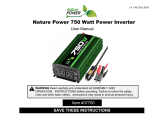
AC Panel
Figure 2-1
AC Panel
Feature Description
1 On/Off Switch turns the inverter’s control circuit on and off. This
switch is not a power disconnect switch. Disconnect DC power
before working on any circuits connected to the inverter.
2 Fault light (red): indicates the inverter has shut down due to
inverter overload, over-temperature, under voltage, over voltage, AC
output short circuit, or AC back-EMF (backfeed) protection
shutdown.
3 Power light (green): indicates the inverter is operating.
4 Status indicator lights: VOLTAGE, CURRENT, AC POWER
When lit, each light indicates which status is being displayed.
REMOTE
SWITCH
DISPLAY
FUNCTION
VOLTAGE
CURRENT
AC POWER
V
A
kW
POWER FAULT
INVERTER
5000
20A 20A
5
6
8
10
1
23
4
7
9
11
12
XPower_Inverter_5000_Owners_Guide.book Page 2 Friday, April 4, 2008 2:59 PM

975-0376-01-01 2–3
5 Status Display: Shows Voltage, Current or AC Power.
VOLTAGE: Indicates battery voltage at the input terminal of the
inverter in volts (V).
CURRENT: Indicates current drawn from the battery by the inverter
in amps (A).
AC POWER: Indicates the output power being drawn from the
inverter in utilized kilowatts (kW).
6 Display Function Button Press this to display battery voltage,
battery current and AC output power.
7 Remote On/Off Switch Connector Port: For connecting the
Remote On/Off Switch. The remote switch and a 10-foot
communications cable is included with the inverter.
8 Two duplex GFCIs: Each GFCI has two three-prong AC outlets and
is connected in series with a 20 A circuit protector.
9 Two 20 A circuit protectors
10 Mounting Flanges (front and rear) allow you to mount the inverter
permanently.
11 Ventilation Openings must not be obstructed for the proper
operation of the inverter.
12 AC Knockout with strain-relief clamp: For hardwiring the inverter
and securing the cables.
Feature Description
XPower_Inverter_5000_Owners_Guide.book Page 3 Friday, April 4, 2008 2:59 PM

Features
2–4 975-0376-01-01
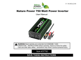
DC Panel
Figure 2-2
DC Panel
Feature Description
1 Chassis Ground Lug connects to vehicle chassis.
2 Ventilation Opening and Fan Assembly must not be obstructed
for the proper operation of the inverter.
3 Negative (–) DC Input Terminal connects to one end of the
negative battery cable. The other end of the negative battery cable is
connected to the negative terminal of the battery.
4 Positive (+) DC Input Terminal connects to one end of the positive
battery cable. The other end of the positive battery cable is
connected to the positive terminal of the battery.
5 Serial number of your inverter.
DANGER:
Thisunitemployscompo-
nentsthattendto producearcsor sparks.
Riskof fireandexplosion– Donot install
near batteries, in machinery space, or
area in which ignition-protected
equipmentis required. Shock Hazard –
Do not open. No serviceable parts inside.
INPUT: 12 Vdc (nominal),
520 A (5 min. max.) / 415 A (cont.)
OUTPUT: 120 Vac / 60 Hz
5 kW / 41 A (5 min max.)
4 kW / 33 A (continuous)
CHASSIS GND
SerialNo.
BATTERY
NEG.
BATTERY
POS.
WARNING:
Shock,energy, andfirehazards. Readmanualbeforeinstallingorusing.Topreventfire,do notcoveror
obstructventilationopenings. Do not mountin zero-clearancecompartment. Overheatingmay result. Do not exposeto rain or
spray. UseGroundFaultCircuitInterruptersonlyas specifiedinthemanualssuppliedwiththisunit. Othertypesmayfailtooperate
when connected to this unit. Ensure proper grounding.Total harmonic distortion is 38%; maximum single harmonic is 32%.
Patents Pending
Designed in Canada by
Xantrex / Assembled in China
1
2
3
4
5
XPower_Inverter_5000_Owners_Guide.book Page 4 Friday, April 4, 2008 2:59 PM

975-0376-01-01 2–5
Remote Switch
Figure 2-3
Remote Switch
Feature Description
1 Remote On/Off Switch turns the inverter’s control circuit on and
off. This switch is not a power disconnect switch. Disconnect DC
power before working on any circuits connected to the inverter.
2 Communications Cable is 10 feet (3 m) long. This cable can be
replaced and/or extended with a standard telephone cable up to a
maximum total length of 25 feet (7.5 m).
1
2
XPower_Inverter_5000_Owners_Guide.book Page 5 Friday, April 4, 2008 2:59 PM

2–6
XPower_Inverter_5000_Owners_Guide.book Page 6 Friday, April 4, 2008 2:59 PM

3–1
3 Operation
Chapter 3 explains how to operate the inverter efficiently and effectively.
Specifically, this chapter:
• Gives procedures for operating the inverter from the front panel
• Discusses operating limits and inverter loads
• Discusses battery charging frequency
• Provides information about routine maintenance
Turning the Inverter On and Off
The On/Off switch on the inverter’s front panel turns the control circuit in
the inverter on and off.
To turn the inverter on and off from its front panel:
• Move the On/Off switch to the On position to turn the inverter on.
• Move the On/Off switch to the Off position to turn the inverter off.
When the switch is Off, the inverter draws a very low current from
the battery.
To turn the inverter on and off from the remote switch:
• Move the On/Off switch to the On position to turn the inverter on.
• Move the On/Off switch to the Off position to turn the inverter off.
When the switch is Off, the inverter draws a very low current from
the battery.
Important:
TURNING THE INVERTER OFF WHEN NOT IN USE.
The inverter draws less than 600 mA from the battery with the On/Off switch
turned on and no load connected, but draws far less than this with the switch
turned off. If the switch is left on, even with no loads the inverter will eventually
discharge the battery.
To prevent unnecessary battery discharge, turn the inverter off when you are not
using it.
WARNING: Shock and energy hazard
The inverter’s On/Off switch (on the front panel and remote switch) does not
disconnect DC battery power from the inverter. You must disconnect DC power
before working on any circuits connected to the inverter.
XPower_Inverter_5000_Owners_Guide.book Page 1 Friday, April 4, 2008 2:59 PM

Operation
3–2 975-0376-01-01
Operating Several Loads at Once
If you are going to operate several loads from the inverter, turn them on
separately after you have turned the inverter on.
Turning loads on separately helps to ensure that the inverter does not have
to deliver the starting current for all the loads at once, and will help
prevent an overload shutdown.
Display Screen
You can monitor important status information on the LED (light emitting
diode) display screen.
To select which information the screen displays, press the Display
Function button. The
VOLTAGE, CURRENT and AC POWER lights indicate
what information the screen is showing.
Battery Voltage
Indicator
The
BATTERY VOLTAGE INDICATOR indicates the DC voltage at the input
terminals of the inverter. At low input currents, this voltage is very close
to the battery voltage. At high input currents, this voltage is lower than the
battery voltage because of the voltage drop across the cable and DC
connections.
Battery Current
Indicator
The
BATTERY CURRENT INDICATOR displays the current draw from the
battery in amps. It will not indicate current draw from other loads
connected to the battery.
Output Power
Indicator
The
OUTPUT POWER INDICATOR indicates the AC output power in kW.
XPower_Inverter_5000_Owners_Guide.book Page 2 Friday, April 4, 2008 2:59 PM
/