
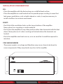
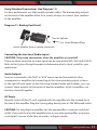
8-Channel Home Theater Amplifier
PT8000CH
Multi-Zone Audio Source Control,
Rack Mount Amp, 8000 Watt

ww w.PyleUSA.com
2
Read through this user manual before using the product to ensure
its correct use. Keep this manual for future reference.
The PT8000CH contains the excellent performance and reliability that PYLEUSA
products have been recognized for. The PT8000CH features the exibility needed
for demanding custom installation applications. It is ideal for use in home theater,
stereo, multi-room, multi-zone and commercial applications.
For best performance, please carefully read the instructions in this manual.
TABLE OF CONTENTS
Features
Front Panel Diagram
Rear Panel Diagram
System Design & Operation Considerations
System Design Examples
Diagram 4 - Multi Room Installation
Diagram 5 - Multi-Zone Installation #1
Diagram 6 - Multi-Zone Installation #2
Diagram 7- Home Theater/Multi-Room Installation
Installation Considerations
Installation
Operation
Troubleshooting
Specications
3
4
4
6
8
9
10
11
12
13
14
18
19
21

ww w.PyleUSA.com
3
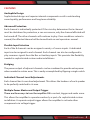
FEATURES
Audiophile Design
Sophisticated design and superior internal components result in outstanding
sound quality, performance and long term reliability.
Advanced Protection
Each channel is individually protected. If the circuitry determines that a channel
must be shutdown for protection, a rare occurrence, only the channel aected will
be turned o. The other channels will continue to play. Once conditions return to
normal, the aected channel will be turned back on and operate as normal.
Flexible Input Selection
Each of the 8 channels can be assigned a variety of source inputs. A dedicated
input can be assigned to each channel. Each channel can also be congured to
play common signals from the Bus or Auxiliary inputs. This provides the exibility
needed in sophisticated custom audio installations.
Bridging
The power output of adjacent channels can be combined to provide extra power
when needed in certain areas. This is easliy accomplished by ipping a single switch.
Individual Channel Level Adjustments
Each channel has its own level adjustment. This allows the loudness of each speaker
to be perfectly matched to its area.
Multiple Power Modes and Output Trigger
There are three ways to turn the amplier ON: constant, trigger and audio sense.
This allows the amplier to operate seamlessly as part of a sophisticated custom
installation. A separate output trigger allows the amplier to activate other
components via voltage trigger.

ww w.PyleUSA.com
4
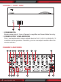
DIAGRAM 1 - FRONT PANEL
1. POWER SWITCH
Master power switch. Turns o power to amplier and Power Mode Circuitry.
2. POWER OUTPUT LEVEL INDICATOR
This is level meter which shows outputs levels of ch 1-2 ch 3-4 ch 5-6 & ch 7-8
condition on the operation. Therefore, you can see output condition thru this
master indicator.
DIAGRAM 2- REAR PANEL
1 2
2 31 4 5 6 7
8
9
10 11
12
13
14
15 16
17 18

ww w.PyleUSA.com
5
1-2. Main bus inputs allow outputs from receivers, CD players, TVs, or any stereo
audio sources to be amplied across all channels for easy multi-room
applications. Auxiliary inputs allows an addition audio source to be played on
any channel that is switched to AUX .
3-4. Bus outputs allows the bus inputs to be sent to other ampliers or a daisy chain
without the need for “Y” cable splitters. Auxiliary output allows you to daisy
chain the input to other audio sources.
5. Bridging switch allows you to easily double the power output by coupling
two channels together.
6. Level controls for each channel.
7. Input Selection switch allows you to select between the common bus and
auxiliary inputs or the individual channel input.
8. One switch allows you to select which stereo Input channel will play through
the speaker outputs: left, right, or left and right combined. lf switched to Left
+ Right, both input channels are combined.
9. Gold plated individual channel inputs allow you to connect dierent audio
sources to each channel.
10. Line signal output
11. Voltage Selector 110-220V
12. The Power Mode switch is used to toggle between three dierent trigger
methods to power up the amplier.
13. 12V output to turn on other devices when amplier is powered up.
Connect to projector screens, powered drapes, or other devices with voltage
triggers.
14. 12-15V A/C or D/C input to trigger power up with voltage from another
device, such as a receiver.
15. Speaker channel output binding posts.
16. Speaker channel bridged mode binding.
17. 3-Prong removable power plug.
18. Fused AC

ww w.PyleUSA.com
6
SYSTEM DESIGN & OPERATION CONSIDERATIONS
To best understand system design and operation of the PT8000CH, it is useful
to understand the following terms and features as they relate to the PT8000CH.
Multi-Room
A system design that plays the same source at the same time in all rooms.
If a change is made in one room, the same changes takes place in all other rooms.
For example, if a listener changes from CD to Tuner in the bedroom, the same
change will be heard in the kitchen.
Note: With the use of volume controls or speaker switchers the volume of each
room can be controlled separately of the other rooms.
Multi-Zone
A system design that allows dierent sources to be played in each room. A change
in one room can be made without changing the other rooms. For example the CD
player can be heard in the bedroom while the kitchen is playing the tuner.
Bridging
The combining of 2 channels to create one mono channel. It is useful when more
volume is needed in a particular area.
Source
Component, audio or video, that provides an audio signal. Examples are CD, VCR,
DVD, tape deck and tuner. The source provides the audio information that is
amplied by the PT8000CH.
Channel
A distinct unit of the amplier that provides output to one speaker. On the
PT8000CH the input to each channel can be congured to select from the BUS
INPUT, the AUX INPUT or that channel’s unique CHANNEL INPUT. Two adjacent
channels can be bridged to provide higher power to one speaker.
Level Controls
Allows any of the channels to be adjusted independently to raise or lower the
output of each channel. This may be used to control the speaker output in order
to balance dierent rooms or areas of the system.

ww w.PyleUSA.com
7
BUS* AUX* LINE Switch
Allows each channel to play a variety of dierent inputs. Depending on the switch
position the channel amplies the signal connected to the BUS input, the AUX
input, or its own LINE input.
R R + L L Switch
When either a BUS or AUX input is selected, this switch is used to direct the channel
to play the left signal from the input “L” or the right signal from the input “R”, or a
combined right and left signal from the input “R+L”.
Bus Input
Allows the signal from a source to be distributed to any of the 12 channels on the
amplier.
Auxiliary Inputs
Allows the signal from a secondary source to be distributed to any of the 12 channels
of the amplier.
Power Mode Selection
There are three ways to turn the amplier on and o. Use the following list to
decide which mode will work best for your application. See Diagram 3 below.
1. Constant
Use this selection when you wish to manually turn the amplier on and o by
using the front mounted power button.
2. Trigger
Use this selection if you wish the amplier turn on when it receives voltage
(12-15V A/C or D/C) from an external source and turn o once that voltage has
stopped. Some components have voltage outputs that are designed for this use.
In addition there are devices that can be used as part of an automated system
that will provide voltage to enable the mode. The voltage source must be
connected to the trigger-input jack on the back of the amplier.
3. Audio Sense
Use this selection when you want the amplier to turn on when the amplier’s
main input receives an audio signal. At the moment that either the left or right
input jacks receive a signal the amplier is turned on. Once the signal stops the
amplier waits 3 minutes and then turns o.

ww w.PyleUSA.com
8
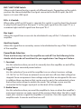
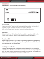
DIAGRAM 3: POWER MODE SELECTION
SYSTEM DESIGN EXAMPLES
There are many ways to congure the PT8000CH amplier. The following pages
contain some typical installation examples. Use these examples to generate
ideas for your system design.
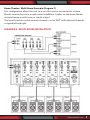
Multi-Room Installation Example (Diagram 4)
This illustrates the simplest use of the PT8000CH, distributing audio throughout
the home. In this example only one source can be selected at a time, all pairs of
speakers have the same audio signal available. The Input Selection switch is set to
“BUS” on all channels. Adjacent channels are assigned left and right.
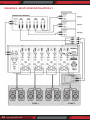
Multi-Zone Example #1 (Diagram 5)
This illustrates the simplest way to provide an audio signal to one area that is
independent of the main audio signal. Zone 2 uses a CD player connected to
just that Zone. The rest of the system operates Zone 1 and is connected to
the preamplier/receiver. The Input Selection switch on channels 1-10 is set to
“BUS” with adjacent channels assigned left and right. The Input Selection Switch
on channels 11 and 12 are set to “LINE”.
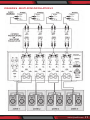
Multi-Zone Example #2 (Diagram 6)
This illustrates the ability to listen to dierent audio signals in each zone, indepen-
dent of every other zone. The system relies on a multi-zone preamplier
or up to 6 independent preampliers.
The Input Selection switch on each channel is set to “LINE”
12-15V AC/DC
TRIGGER INPUT
12-15V AC/DC
TRIGGER INPUT
12V CONTROL
OUTPUT
AUDIO SENSE CONSTANT
2.1mm x 5.5mm
Power Input Jack
Mode Switch 3.5mm Power
Output Jack

ww w.PyleUSA.com
9
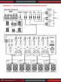
Home Theater / Multi-Room Example (Diagram 7)
This conguration allows the user to access the sources connected to a home
theater receiver for use in a multi-room installation. It relies on the home theater
receiver having a multi-room or similar output.
The Input Selection switch on each channel is set to “BUS” with adjacent channels
assigned left and right.
DIAGRAM 4 - MULTI-ROOM INSTALLATION

ww w.PyleUSA.com
10
DIAGRAM 5 - MULTI-ZONE INSTALLATION #1

ww w.PyleUSA.com
11
DIAGRAM 6 - MULTI-ZONE INSTALLATION #2

ww w.PyleUSA.com
12
DIAGRAM 7 - HOME THEATER/MULTI-ROOM INSTALLATION

ww w.PyleUSA.com
13
INSTALLATION CONSIDERATIONS
DO:
• Place the amplier with the feet resting on a solid at level surface.
• Place the amplier in a well-vented area to provide proper cooling. In areas that
lack proper ventilation, such as tight cabinets or racks, it may be necessary to
install small fans to create air movement.
DON’T:
• Don’t block the ventilation holes on the top or bottom of the amplier.
Never place it on carpeting or similar material.
• Don’t place the amplier in any other position other than horizontal with the feet
down. Never place on its side or resting on the back where the terminals are
located.
• Don’t the amplier near heat sources, or in an area that it would be exposed to
moisture.
YOU SHOULD KNOW
• The power supply is very large and therefore may cause a hum to be heard in
some components if they are placed very close to the amplier.

ww w.PyleUSA.com
14
INSTALLATION
CAUTION: All connections and switching must be done with the amplier’s
master power switch positioned to “o”.
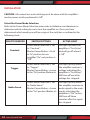
Select the Power Mode Selection
Refer to the Power Mode Selection area under installation considerations to
determine which setting to use to turn the amplier on. Once you have
determined which mode you will be using set the switches as outlined in the
following chart:
SELECTION MODE SWITCH SETTINGS ACTIVE LIGHT
Constant
Power Mode Selection = Set
to “Constant”.
Master Power Button = Push
to “In” position to turn
amplier “On”, out position is
“O”
Will light up when the
amplier is “On/Active”
and will go o when it
is “o”
Trigger
Power Mode Selection = Set
to “Trigger”.
Master Power Button = Leave
in the “On” position (Button in).
Will light up only when
the amplier receives a
voltage indicating the
amplier is “On/Active”.
Will turn o once the
voltage has stopped.
Audio Sense
Power Mode Selection = Set
to “Audio Sense”.
Master Power Button = Leave
in the “On” position (Button in)
Will light up only when
the amplier receives an
audio signal to the main
inputs indicating the
amplier is “ON”/active.
Will turn o three
minutes after the signal
has stopped

ww w.PyleUSA.com
15
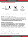
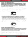
Selecting Inputs (See Diagrams 8 & 9)
Each channel is capable of delivering the source from many inputs. The three
main inputs are BUS, AUX and LINE IN. The selection for these inputs is done
via the Input Selection switch, marked “BUS-AUX-LINE”. To select a source for
each channel, follow the steps below:
1. Select the desired source input. Set the Input Selection switch to BUS (will play
source connected to the BUS INPUT), AUX (will play source connected to the
AUX INPUT) or LINE (will play source connected to the LINE IN).
2. The BUS and AUX inputs each have a left and right input. The left, right or
combined left and right signal from these may be selected via the switch
marked “R R+L L”. Select the side you want the channel to deliver. Selecting “R” ±
will play the right channel of the selected input. Selecting “L” will play the left
channel of the selected input. Selecting “R+L” will play the combined signals of
right and left.
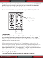
Selecting Bridge Mode (See Diagram 10)
Under normal operation, this should be left in the 8 ohm position. It is sometimes
desirable to combine two channels into one through bridging. The output of the
combined channels can then be used to power one speaker.
To bridge two adjacent channels rst make sure that the Impedance Switch is
in the 8ohm position. Next move the switch marked “BRIDGE” to the “ON” position.
BUS.AUX.LINE
Diagram 8
R R+L R
Diagram 9

ww w.PyleUSA.com
16
The speaker must be connected to the terminals immediately under the “BRIDGED”
text as indicated in Diagram 10. All input selection and settings for the bridged
channels will be done on the channel to the left.
Do not connect more than one speaker to the outputs of the bridged channel.
Control Output
The 12V output jack on the back of the amplier can be used to turn on a variety
of components equipped to be activated when they receive a 12V DC output.
Voltage is only delivered to the jack when the amplier is “on” or active. When the
amplier turns o, the voltage ceases.
Before connecting another device to the 12 output please make sure that the
device can accept 12V DC at 150ma. To connect the output to another device you
must access the output jack with a two-conductor plug that ts into the 3.5mm
jack. Be aware that the tip of the plug will be (+). If you are unsure about using this
feature please contact an authorized PYLEUSA dealer for assistance.
Connecting the Speaker Wires
CAUTION: Only make connections when the amplier is turned o.
Diagram 10
To “ON” position
(+) (-)
Wires to speaker

ww w.PyleUSA.com
17
Using Standard Connections (See Diagram 11)
For best performance use high quality speaker cables. The banana plug outputs
on the back of the amplier allow for a variety of ways to connect your speakers
to the amplier.
Diagram 11: Binding Post Detail
Connecting the Line Level Audio Inputs
CAUTION: Only make connections when the amplier is turned o.
There are three areas that an input signal can be connected, BUS, AUX and LINE IN.
Refer to the System Design Examples to determine which is best suited for your
application.
Audio Outputs
Sources connected to the “BUS” or “AUX” inputs can be forwarded to other
components or ampliers by connecting to the corresponding output sections
to the right of each input section. By using standard audio patch cables, you can
connect these outputs to the inputs of another amplier. Up to 5 ampliers can
be daisy-chained together.
AC Power
Plug the socket of the AC cord supplied with the amplier into the receptacle on
the rear of the amplier. Plug the 2 prong plug directly into a 120V 60Hz wall outlet.
CAUTION: Do not plug the amplier into the preamplier or receivers switched
outlet. If you wish to have the amplier turn on once the preamplier or receiver
is activated, use one of the turn on modes, voltage or audio.
Insert speaker wire or spade connector
Turn to tighten
Insert Banana Plug

ww w.PyleUSA.com
18
OPERATION
See Diagram 1 for the location of the following:
Power Switch
The switch marked “Power” on the front panel of the amplier will turn o all
amplier circuitry no matter which turn on mode is selected.
Refer to the “Power Mode Selection” section for further information.
Active LED
When lit, the Active LED indicates that the amplier is operating. Refer to the
“Power Mode Selection” section of this manual for further information.
Protection LEDs
When lit the “Protection” LEDs located on the front of the amplier indicate that
either a fault in the wiring, the speaker, or the amplier has caused the channels
associated with the LED to shut down.
Level Adjustment Knobs
The level adjustment knobs on the back panel of the amplier can be used to
adjust the level of each channel. There are many reasons for needing to adjust the
level. You many wish to closely match other levels in the system, or you may wish
to limit the volume level in an area, such as a child’s room.

ww w.PyleUSA.com
19
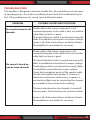
TROUBLESHOOTING
The amplier is designed to function trouble-free. Most problems occur because
of operating errors. If you have a problem please check the troubleshooting list
rst. If the problem persists, contact your authorized dealer.
PROBLEM POSSIBLE CAUSES AND SOLUTIONS
No sound is heard on all
channels
Audio cable to the source component is not
connected properly or the cable is bad. Use another
cable that you know is good.
The Input Selection switch is positioned incorrectly.
Refer to installation instructions for proper settings.
Some or all of the internal fuses are blown. Return
the amplier to your dealer for servicing.
No sound is heard on
one or some channels
Audio cable to the source component is not
connected properly or the cable is bad. Use another
cable that you know is good.
The Input Selection switch is positioned incorrectly.
Refer to installation instructions for proper settings.
The Bridging switch is positioned incorrectly. Refer
to installation instructions for proper settings.
Check the termination points of the speaker cable
at both the amplier and speaker. If Connector,
check the connections at the levers. A speaker is
not working. Make sure by connecting the channel
to a speaker that you know to be working.
The level adjustment on the channel is turned all
the way down. Turn it clockwise to raise the volume.
Some or all of the internal fuses are blown. Return
the amplier to your dealer for servicing.

This product can expose you to a chemical or group of chemicals, which may include
“Nickel Carbonate” which is known in the state of California to cause cancer, birth defects,
or other reproductive harm. For more info, go to https://www.p65warnings.ca.gov/.
ww w.PyleUSA.com
20
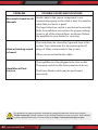
PROBLEM POSSIBLE CAUSES AND SOLUTIONS
No sound is heard on all
channels
Audio cable to the source component is not
connected properly or the cable is bad. Use another
cable that you know is good.
The Input Selection switch is positioned incorrectly.
Refer to installation instructions for proper settings.
Some or all of the internal fuses are blown. Return
the amplier to your dealer for servicing.
Hum or buzzing sound
is heard.
The sound may be caused by a ground loop in the
system. Try to eliminate this by reversing the AC
plugs of other components in the system.
Other causes include faulty cables.
Amplier will not
turn on
The amplier must be plugged into a live outlet.
The power switch on the front panel must be on.
The Power Mode switch may be positioned
incorrectly.
Page is loading ...
Page is loading ...
-
 1
1
-
 2
2
-
 3
3
-
 4
4
-
 5
5
-
 6
6
-
 7
7
-
 8
8
-
 9
9
-
 10
10
-
 11
11
-
 12
12
-
 13
13
-
 14
14
-
 15
15
-
 16
16
-
 17
17
-
 18
18
-
 19
19
-
 20
20
-
 21
21
-
 22
22


