PyleHome PT110 80 Watt AC/DC Microphone PA Mono Amplifier User manual

Category
CD radios
Type
User manual

This manual is also suitable for

80 Watt AC/DC Microphone
PA Mono Amplifier with USB/SD/FM/BT
PT110
LED Level Display w/ 70V Output & Mic Talkover
ww w.PyleUSA.com
2
INTRODUCTION
Your New PYLE PT110 PA AMPLIFIER gives you the power and versatility you
need in a professional sound system. The amplier's wide frequency response
makes it suitable for amplifying music or vocal program material. It can be used
for live bands, oce paging systems, public announcements, or a variety of
other installations. Please read this manual throughly before you attempt to
set up and use the amplier. It contains a range of installation suggestions as
well as instructions to ensure safe usage. Installed properly, you can expect
years of trouble-free service from this product.
FEATURES AND CONTROLS
FRONT PANEL
REAR PANEL
1. POWER SWITCH: Press to switch the power unit ON or OFF.
2. Phone Jack: Connect a pair of stereo headphones for private listening or
cueing (monitoring) sound prior to airing” it.
12
4
3 8 5
6
7
9
10
11
15
1816
17
22
14
12
13
20
19
21
ww w.PyleUSA.com
3
3. MIC 1 & MIC 2 Jack: Allows you to connect up to two 6.35mm type microphone.
4. LED Level Display Meter
5. MIC Volume Control: Lets you adjust the MIC1/MIC2 sound level.
6. Three Input Sources Mixing Controls: Controls the sound level for each of the
audio input sources.
PHONO/AUX: Select and connect an alternative high level (AUX/CD) or low level
(PHONO) audio sound source.
7. 100 Hz, 1 kHz, & 8 kHz Equalizer Controls: To enhance the sound or tailor the
high, midrange, and low frequencies for each audio source input to the acoustics
of a particular performance environment, you can adjust these equalizer tone
controls.
8. AUX Input Jack: Allows you to connect any high level sound source, such as a
CD player, tape deck, or tuner, to the CD/AUX jack.
9. CONTROL PANEL BUTTON
A. These buttons are only used to control the USB/SD, Wireless BT and FM
functions and doesn’t control other functions.
B. MODE BUTTON: Press this button to select one from USB/SD mode, FM mode
or Wireless BT play mode. USB/SD mode will be set automatically after turning
ON the unit. Automatically plays mp3 les after inserting a USB ash drive or
SD card. You cannot select AUX, CD and DVD input on this button.
C. Each press of the PLAY/PAUSE BUTTON causes the operation to change from
play to pause or from pause to play in the USB/SD mode or Wireless BT mode.
Press the PLAY/PAUSE BUTTON one time to auto scan all frequencies from
87.5MHz to 108MHz in FM mode Press the button to auto scan channels when
you use FM radio for the rst time. After stop searching, the unit will auto
store all the radio channels and play from the rst radio channel. You don't
need to rescanevery FM radio start up.
D. PREV and NEXT BUTTON: Use these two buttons to select previous or next
track, depending on these dierent modes as below.
In USB/SD mode: Use to select previous or next track.
In Wireless BT mode: Use to select previous or next track.
In FM mode: Use to select previous or next radio channel.
10. LED Display: Show MP3/SD/BT/FM information.
11. USB Port and SD card socket: After inserting a USB ash drive/SD Card into
the input terminal, then press the mode button to choose between audio from
the USB port, SD Card input, Wireless BT or FM radio. If you want to use the
Wireless BT, check the below steps.
ww w.PyleUSA.com
4
STEPS FOR CONNECTING WITH WIRELESS BT DEVICE
A. Press MODE button under the ID3 display screen and enter into BT mode.
B. Search for the Wireless BT device and nd the BT name PYLEUSA or BT
C. Select the PYLEUSA or BT Wireless BT name and wait for the device to pair.
D. The unit will make a sound conrming that the devices have successfully paired.
E. Once paired you can play music from your bt device. You can also use the control
buttons on the unit to select the tracks from your bluetooth device.
12. Voltage Switch: The amplier has selectable input voltage from 110V/60Hz
which is the standard in USA and CANADA. You can also switch the input
voltage to 220V/50Hz for EUROPEAN operation. Please make sure the switch is
in the proper position before operating, otherwise severe damage will result
not cover by the warranty. Please also replace the fuse with proper rating in
this situation (see the SPECIFICATIONS for the fuse rating).
13. GND (GROUND) screw terminal: If you connect a low level audio input source
(turntable) to the PHONO, please connect your turntable's ground wire (usually
black or green) to the amplier’s GND terminal, to avoid a low frequency hum.
You can also use this screw to ground any other system connection.
14. Unswitched AC Accessory Outlet - 300W MAX.
15. PHONO Input Jack: You can connect a low level audio input source, such as a
magnetic cartridge turntable to the L PHONO and R PHONO jacks.
16. AUX/CD Input Jack: Allows you to connect any high level sound source, such
as a CD player, tape deck, or tuner, to the CD/AUX jack.
17. PHONO and AUX/CD Input Selector: Lets you select the input source you
want to connect to the amplier.
18. MIX BUS Jack: Allows you to connect another units to this jack to double the
size of your PA system.
19. Push-Terminal Connectors: Let you easily connect speaker wires directly to
the ampliers.
20. Wireless BT Anntena: Pull the antenna out when using Wireless BT input.
21. FM Anntena: Pull the the antenna when using FM input.
22. DC 4A/12V Input Jack: Allows you to connect the power for amplier from
12-volt battery source.
INSTALLATION GUIDELINES
Input connections
The Unit accept a board range of input sources, including:
Microphones (up to two simultaneously)
Compact Disc (CD) player
Cassette, Reel-to-Reel or other tape player Radio Tuner
Magnetic Cartridge Turntable
ww w.PyleUSA.com
5
Connecting Microphones
The MIC 1 and MIC 2 jacks permit you
to connect two microphones with
6.35mm plug.
Connecting a CD or Tape Player, or
Tuner
In this Situation, set the PHONO and
AUX/CD SELECTOR switch to the AUX/CD
Connecting a Turntable
In this Situation, set the PHONO and
AUX/ CD SELECTOR switch to the
PHONO.
Speaker Connections
One or more speakers (4, 8, or 16-Ohm)
speakers can be connected to the
amplier with or without transformers.
However, before you connect any speaker
to the amplier, the total speaker impe-
dance must be calculated in order to
avoid damage to the amplier.
A total speaker impedance greater than
16 Ohms or less than 4 Ohms can be
cause this damage to occur. To begin
with, in order to ensure equal volume
from each speaker, all connected
speakers should have the same impe-
dance. A proper total impedance with
the 4 to 16 Ohms range can be achieved
by combining series and paralled
speaker connections. Please see the
diagrams which follow the same impe-
dance. Finally, always use the shortest
length of speaker wire possible of proper
gauge. Usually, 18-gauge wire is ade-
quate for lengths under 25 feet, while
16-gauge is used for greater lengths.
System 1: Single speaker system
1. Connect the speaker (-) terminal to
the amplier COMMON terminal
2. Depending on the speaker being
used, connect the speaker (+)
terminal to the amplier's 4-Ohm, 8-
Ohm or 16-Ohm amplier terminal.
mic 1
mic 2
Set the switch to AUX/CD
position
CD, Tape player or Tuner
R
L
Set the switch to PHONO
position
Turntable
R
L
+
-
This example shows a 4 Ohm Speaker
ww w.PyleUSA.com
6
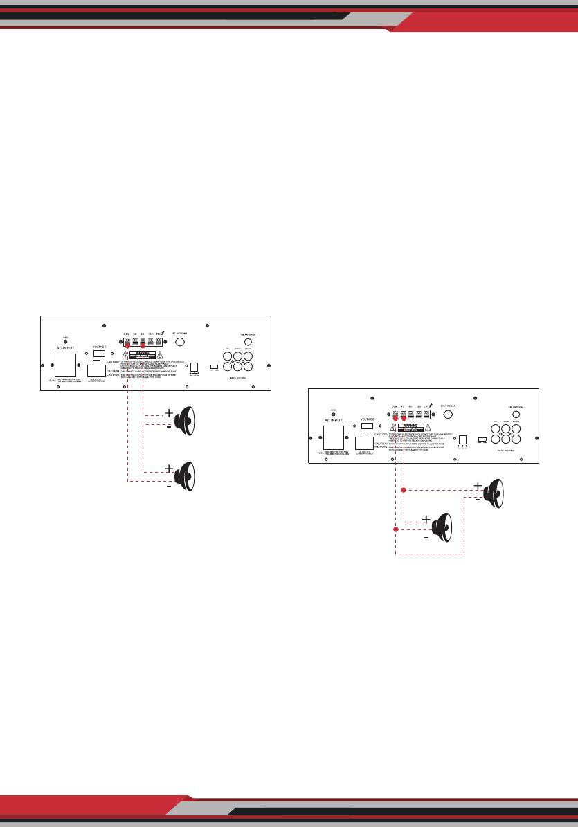
System 2: Two (or more) speakers in
series
1. Connect the LEFT SPEAKER (-) to the
amplier COMMON terminal.
2. Connect the LEFT SPEAKER (+) to the
RIGHT SPEAKER (-).
3. Connect the RIGHT SPEAKER (+) to the
amplier's 4-Ohm, 8-Ohm, or 16-Ohm
terminal, depending on the TOTAL
IMPEDANCE of the two speakers.
If each speaker has an impedance of
8 Ohms, the total speaker impedance
in this series conguration is 16 Ohms.
NOTE:
ADDITIONAL SPEAKERS MAY BE
INCLUDED IN SERIES, BUT IT IS NECES-
SARY TO CALCULATE TOTAL IMPE-
DANCE, AND CONNECT THE SPEAKER
CIRCUIT TO A TERMINAL OF APPRO-
PRIATE IMPEDANCE. FOR EXAMPLE, IF
THREE SPEAKERS OF 4-OHM ARE
USED, TOAL IMPEDANCE IS 12 OHMS,
YOU SHOULD CONNECT TO THE
16-OHM TERMINAL.
System 3: Two (or more) speakers in
parallel
1. Connect the LEFT SPEAKER (-) to the
RIGHT SPEAKER (-).
2. Connect BOTH the LEFT SPEAKER (-)
and the RIGHT SPEAKER (-) to the
amplier COMMON terminal.
3. Connect the LEFT SPEAKER (+) to the
RIGHT SPEAKER (+).
4. Connect BOTH the LEFT SPEAKER (+)
and RIGHT SPEAKER (+) to the
amplier 4-Ohm, 8-Ohm or 16-Ohm
terminal, depending on the TOTAL
IMPEDANCE of the two speakers.
If each speaker has an impedance of
8-Ohm, the total speaker impedance
in this parellel conguration is 4 Ohms.
System 4: Four speakers in series/
parallel combination
1. Group the four speakers into two pairs.
2. Connect each pair of speakers in
SERIES (see system 2 above). If you
connect 8-ohm speakers, the total
impedance of each pair is 16 ohms.
Right Speaker
Left Speaker
This example shows a two 4 Ohm Speakers,
the total impedance is 8 ohms.
Right Speaker
Left Speaker
This example shows a two 8 Ohm Speakers,
the total impedance is 4 ohms.
ww w.PyleUSA.com
7
3. Connect the two pairs of speakers in PARALLEL. If you connect 8-ohm speakers,
the total impedance of both pairs is 8 ohms.
Note:
If each of the four speakers is 8 ohms, the total speaker impedance of the combined
series/parallel connection described above is also 8 ohms. Likewise, the total
speaker impedance is 4 or 16 ohms, if the speakers are 4 or 16 ohms respectively.
4. Connect the speakers' (-) terminals to the amplier's COMMON terminal.
5. Connect the speakers' (+) terminals to the amplier's 4-Ohm, 8-Ohm, or 16-Ohm
terminal, depending on the TOTAL IMPEDANCE of the FOUR SPEAKERS.
See the chart below for some samples system suggestions:
This example shows four 8 Ohm
Speakers, the total impedance is
8 ohms.
ww w.PyleUSA.com
8
SERIES/PARALLEL VARIATIONS
Although the description above is for combining TWO SERIES PAIRS in a PARALLEL
hook up, you may also select to combine a SERIES PAIR and a PARALLEL PAIR in a
PARALLEL hook up. Simply be sure you have properly calculated the total impe-
dance, and connect the (+) speaker circuit wire to the proper amp terminal.
For example, if you use a SERIES PAIR of 8-Ohms speakers (the total impedance is
16 ohms) and a PARALLEL PAIR of 8-Ohms speakers (the total impedance is 4 ohms)
in a PARALLEL hook up, the TOTAL IMPEDANCE of this system is 3.2 OHMS, so you
should connect the (+) speaker circuit wire to the 4-OHM terminal.
See the chart below for some samples system suggestions:
COMBINATION OF ONE SERIES PAIR AND ONE PARALLEL PAIR IN PARALLEL
+
-
+
-
+
-
+
-
8
8
8
8
Four 8 Ohm
Speakers
ww w.PyleUSA.com
9
This example shows for the rst three systems in chart. In this case, 4-Ohm terminal
is used your system impedance may be varied depending on the impedances of
the individual speakers, and may reguire hook up to the 8 or 16 Ohms terminal.
System 5: Connecting speakers with transformers
1. Locate the input taps on your transformer. These taps are on side of the trans -
former, and are rated in watts, 10, 5, 2.5, 1.25 or 0.62. Usually, each speaker in a
system uses the same wattage tap. Connect the selected tap to the amplier
70V RMS terminal. If you wish a particular speaker to have a higher volume level,
connect the wire from 70V RMS to a higher wattage tap on the transformer.
2. Connect the transformer's COMMON tap on the primary side to the amplier
COMMON terminal.
3. Connect the speaker's (+) terminals to the transformer's secondary tap that
matches the speaker's TOTAL IMPEDANCE. Locate on the opposite side of the
transformer, these secondary taps are outputs, and are rated in Ohms 4, 8 or 16.
4. Connect the speaker's (-) terminals to the transformer's COMMON tap on the
secondary side.
NOTE:
Before connecting the speakers, please be sure the total wattage of the primary
tap you use does not exceed the amplier's maximum power rating, PT110 20W
and PT210 40W.
Avoid, where possible, multiple connections to the 70V RMS and COMMON
terminals.
4 Ohm 10w
Speaker
+
-
0.62
1.25
2.5
5
10
com
(watts)
com
(ohms)
16
8
4
ww w.PyleUSA.com
10
Using Headphones
To listen privately, or to monitor sound sources, connect a pair of low impedance
stereo headphones (not supplied) with 6.35mm plug into the PHONES jack on the
amplier front panel.
Please listen safely. Follow these recommendations:
Do not listen at extremely high volume levels. Extended, high-volume listening
can lead to permanent hearing loss. Always start with the volume control set to a
LOW level BEFORE you put the headphones on. Then gradually increase the volume
as necessary.
Connecting to standard AC power
After making all other connections, set the POWER switch to OFF position. Then
connect the power cord to a standard AC outlet.
Connecting to 4A/12V DC power
You can power the amplier from your vehicle's 12-volt battery. Connect the supplied
DC power cable's barrel plug to DC 12V IN jack on the amplier, and then connect
the cable's other end to the 12-volt accessory socket on the vehicle, such as the
cigarette-lighter socket.
CAUTIONS:
PLEASE UNPLUG THE AC POWER CORD BEFORE CONNECTING THE DC POWER
CABLE FOR THIS 12V POWER USAGE, AND DISCONNECT THE DC POWER CABLE
BEFORE PLUGGING IN THE AC POWER CORD FOR AC POWER USAGE.
THE VEHICLE USING THIS POWER SOURCE MUST HAVE A NEGATIVE GROUND
ELECTRICAL SYSTEM. IF YOU ARE NOT SURE OF IT, PLEASE CHECK WITH YOUR
VEHICLE'S DEALER.
Turning the amplier ON
1. Turn on the audio input source equipment which is connected to the amplier
INPUT jack.
2. Set all volume levels (MASTER, MIC 1, MIC 2, and PHONO/AUX) to their minimum
level settings.
3. Press the power switch to turn the amplier on.
ww w.PyleUSA.com
11
4. Adjust the controls of MIC 1, MIC 2, and PHONO/AUX to the achieve desired
volume and balance. Using the LED power meter The meter LED position indicate
the amplier output power.
Using the MASTER volume control
The MASTER volume control increases or decreases output level gain. To obtain
best performance with the least distortion, be sure to adjust the output level so
that the LED meter does not continually exceed the right extreme of the meter's
range.
CAUTION: Setting output level too high can overdrive the amplier, causing
permanent damage.
Using the MIX BUS jack
You can connect another PT110/ PT210 to this jack to double the size of your PA
system. This lets you use up to four microphones and two turntables (or two
auxiliaryies) sound souces. Use a shield cable with phono plugs at each end, and
connect the cable between the MIX BUS jacks on the back of two ampliers.
For the best results, do not use a cable longer that 6 feet.
Mix Bus Jack
ww w.PyleUSA.com
12
Remote control
Features:
1/4'' Phone Jack
LED Level Display
Master Volume Control
Tone Control
Mix Bus Jacks
Front 3.5mm AUX CD Input Jack
MIC 1/MIC 2 Talkover
DC 12V Inlet
Phono/Aux Volume Control
Mic 1 Mic 2 Volume Controls
Mic 1 Mic 2 6.35mm Connectors
Removable AC Cord
Unswitched AC Outlet
Phono/Aux/RCA Input Jacks
Phono/Aux Input Selector
1
2
3
4
5
6
7
8
9
1. Press this button to turn ON or OFF the MP3.
2. When in the FM mode, press this two
buttons to tune FM Frequency.
3. Press these two buttons to select the
previous or next track in USB or SD or
Wireless BT mode, to select previous or
next channel in FM model.
4. Volume up or down
5. Press the numbers to select the tracks
directly. The unit takes 1-2 seconds to
response in USB or SD mode.
6. Press this button to repeat mode.
7. Press this button to select the playing
mode, such as USB/SD/FM/WIRELESS BT
8. EQ function: Select a pre-set mode of the
equalizer that is designed accordingly.
9. Play and Pause function for MP3 in
USB/SD/BT model. Press this button to
auto scan the channel in FM model, and
auto store channel.
ww w.PyleUSA.com
13
Variety of Speaker Outputs Terminal
USB/SD/FM/ LED Display & Wireless BT Features
Includes Wireless BT Antenna to Improve BT Distance
Includes FM Antenna to Improve FM Sensitivity
Wireless BT Connectivity:
Simple & Hassle-Free Pairing Ability
Works with All of Todays Latest Devices
(Smartphones, Tablets, Laptops, Computers, etc.)
Wireless BT Network Name: PYLEUSA
Wireless BT Version: 5.0
Wireless Range: 40’ + ft.
What's in the Box:
PA Microphone Mono Amplier
Remote Control
FM Antenna
Technical Specs:
Power Supply: 80 Watt
Power Output: 70V
Voltage Selector: 120/240V
Construction Material: Iron
Frequency Response: 50Hz - 20kHz
Battery Operated Remote, Requires (1) x CR-2025 Button Cell Battery, Included
Impedance: 4 Ohm, 8 Ohm, 10 Ohm, 70V
Product Dimension (L x W x H): 12.6’ x 10’ x 3.75’ -inches
This product can expose you to a chemical or group of chemicals, which may include
“Nickel Carbonate which is known in the state of California to cause cancer, birth defects,
or other reproductive harm. For more info, go to https://www.p65warnings.ca.gov/.
Questions? Issues?
We are here to help!
Phone: (1) 718-535-1800
Email: suppor[email protected]om
  • Page 1 1
  • Page 2 2
  • Page 3 3
  • Page 4 4
  • Page 5 5
  • Page 6 6
  • Page 7 7
  • Page 8 8
  • Page 9 9
  • Page 10 10
  • Page 11 11
  • Page 12 12
  • Page 13 13
  • Page 14 14

PyleHome PT110 80 Watt AC/DC Microphone PA Mono Amplifier User manual

Category
CD radios
Type
User manual
This manual is also suitable for

Ask a question and I''ll find the answer in the document

Finding information in a document is now easier with AI