ESAB EPP-450 Plasma Power Source User manual
- Category
- Welding System
- Type
- User manual

Instruction Manual - EN
0558007946 08/2014
Plasma Power Source
EPP-450

This equipment will perform in conformity with the description thereof contained in this manual and accompa-
nying labels and/or inserts when installed, operated, maintained and repaired in accordance with the instruc-
tions provided. This equipment must be checked periodically. Malfunctioning or poorly maintained equipment
should not be used. Parts that are broken, missing, worn, distorted or contaminated should be replaced imme-
diately. Should such repair or replacement become necessary, the manufacturer recommends that a telephone
or written request for service advice be made to the Authorized Distributor from whom it was purchased.
This equipment or any of its parts should not be altered without the prior written approval of the manufacturer.
The user of this equipment shall have the sole responsibility for any malfunction which results from improper
use, faulty maintenance, damage, improper repair or alteration by anyone other than the manufacturer or a ser-
vice facility designated by the manufacturer.
BE SURE THIS INFORMATION REACHES THE OPERATOR.
YOU CAN GET EXTRA COPIES THROUGH YOUR SUPPLIER.
These INSTRUCTIONS are for experienced operators. If you are not fully familiar with the
principles of operation and safe practices for arc welding and cutting equipment, we urge
you to read our booklet, “Precautions and Safe Practices for Arc Welding, Cutting, and
Gouging,” Form 52-529. Do NOT permit untrained persons to install, operate, or maintain
this equipment. Do NOT attempt to install or operate this equipment until you have read
and fully understand these instructions. If you do not fully understand these instructions,
contact your supplier for further information. Be sure to read the Safety Precautions be-
fore installing or operating this equipment.
CAUTION
USER RESPONSIBILITY
READ AND UNDERSTAND THE INSTRUCTION MANUAL BEFORE INSTALLING OR OPERATING.
PROTECT YOURSELF AND OTHERS!


4

5
TABLE OF CONTENTS
1.0 Safety Precautions ....................................................................................7
2.0 Description ...........................................................................................9
2.1 Introduction ......................................................................................9
2.2 General Specications ............................................................................9
2.3 Dimensions and Weight..........................................................................10
3.0 Installation...........................................................................................11
3.1 General..........................................................................................11
3.2 Unpacking ......................................................................................11
3.3 Placement.......................................................................................11
3.4 Input Power Connection .........................................................................12
3.4.1 Primary Power.............................................................................12
3.4.2 Input Conductors .........................................................................13
3.4.3 Input Connection Procedure...............................................................13
3.5 Output Connection ..............................................................................14
3.5.1 Output Cables (customer supplied).........................................................14
3.5.2 Output Connection Procedure - Single Power Source .......................................14
3.6 Parallel Installation...............................................................................15
3.6.1 Connections for Two EPP-450’s in Parallel ..................................................16
3.6.2 Marking with Two Parallel EPP-450’s .......................................................19
3.7 Interface Cables ................................................................................ 20
3.7.1 CNC Interface Cables with Mating Power Source Connector and
Unterminated CNC Interface...............................................................21
3.7.2 CNC Interface Cables with Mating Power Source Connectors at Both Ends ..................21
3.7.3 Water Cooler Interface Cables with Mating Power Source Connectors at Both Ends ......... 22
4.0 Operation .......................................................................................... 23
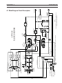
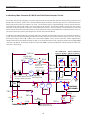
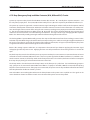
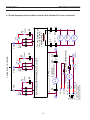
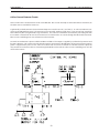
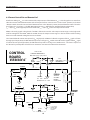
4.1 Block Diagram Circuit Description ............................................................... 23
4.2 Control Panel................................................................................... 26
4.2.1 Modes of Operation: Cutting and Marking Mode .......................................... 29
4.3 Sequence of Operation ......................................................................... 30
4.4 Arc Initiation Settings ............................................................................31
4.4.1 Enable / Disable Arc Initiation Conditions ...................................................32
4.4.2 Adjust Arc Initiation Dwell Timer . . . . . . . . . . . . . . . . . . . . . . . . . . . . . . . . . . . . . . . . . . . . . . . . . . . . . . . . . . .32
4.4.3 Adjusting the Minimum Start Current ......................................................32
4.4.4 Arc Initiation Controls......................................................................33
4.4.5 Start Current and Up-Slope Timer ..........................................................33
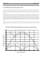
4.5 EPP-450 V-I Curves.............................................................................. 34
4.5.1 EPP-450 V-I Curves for all models.......................................................... 34
5.0 Maintenance.........................................................................................35
5.1 General..........................................................................................35
5.2 Cleaning ........................................................................................35
5.3 Lubrication ..................................................................................... 36
Section / Title Page

6
TABLE OF CONTENTS
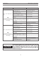
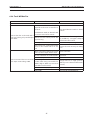
6.0 Troubleshooting .....................................................................................37
6.1 General..........................................................................................37
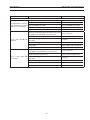
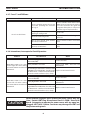
6.2 Fault Indicators ..................................................................................37
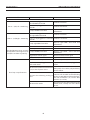
6.3 Fault Isolation .................................................................................. 40
6.3.1 No Output with Contactor Signal Applied ................................................. 40
6.3.2 Output Limited to 100A................................................................... 40
6.3.3 Fans Not Working ........................................................................ 40
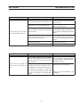
6.3.4 Power Not On or Low Voltage..............................................................41
6.3.5 Fault Light Illumination ....................................................................41
6.3.6 Torch Will Not Fire ........................................................................ 45
6.3.7 Fuses F1 and F2 Blown.................................................................... 46
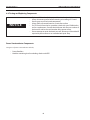
6.3.8 Intermittent, Interrupted or Partial Operation.............................................. 46
6.4 Testing and Replacing Components ............................................................. 48
6.4.1 Power Rectiers .......................................................................... 49
6.4.2 IGBT / Freewheeling Diode (FWD) Replacement ............................................51
6.4.3 Power Shunt Installation ...................................................................53
6.4.4 Procedure for Verifying Calibration of Digital Meters ....................................... 54
6.5 Control Circuit Interface Using J1 and J6 Connectors ............................................. 54
6.6 Auxiliary Main Contactor (K3) and Solid State Contactor Circuits .................................. 56
6.7 Main Contactor (K1A, K1B and K1C) Activation Circuit............................................. 57
6.8 Arc Current Detector Circuits.................................................................... 58
6.9 Current Control Pot and Remote Vref .............................................................59
6.10 Pilot Arc HI / LO and Cut / Mark Circuits ......................................................... 60
6.11 Low Current Range .............................................................................61
7.0 Replacement Parts .................................................................................. 63
7.1 General......................................................................................... 63
7.2 Ordering ....................................................................................... 63
Section / Title Page

7
SECTION 1 SAFETY PRECAUTIONS
1.0 Safety Precautions
Users of ESAB welding and plasma cutting equipment have the ultimate responsibility for ensuring that
anyone who works on or near the equipment observes all the relevant safety precautions. Safety precautions
must meet the requirements that apply to this type of welding or plasma cutting equipment. The following
recommendations should be observed in addition to the standard regulations that apply to the workplace.
All work must be carried out by trained personnel well acquainted with the operation of the welding or plasma
cutting equipment. Incorrect operation of the equipment may lead to hazardous situations which can result in
injury to the operator and damage to the equipment.
1. Anyone who uses welding or plasma cutting equipment must be familiar with:
- its operation
- location of emergency stops
- its function
- relevant safety precautions
- welding and / or plasma cutting
2. The operator must ensure that:
- no unauthorized person stationed within the working area of the equipment when it is started up.
- no one is unprotected when the arc is struck.
3. The workplace must:
- be suitable for the purpose
- be free from drafts
4. Personal safety equipment:
- Always wear recommended personal safety equipment, such as safety glasses, ame proof
clothing, safety gloves.
- Do not wear loose tting items, such as scarves, bracelets, rings, etc., which could become
trapped or cause burns.
5. General precautions:
- Make sure the return cable is connected securely.
- Work on high voltage equipment may only be carried out by a qualied electrician.
- Appropriate re extinquishing equipment must be clearly marked and close at hand.
- Lubrication and maintenance must not be carried out on the equipment during operation.
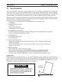
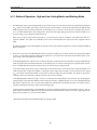
The IP code indicates the enclosure class, i.e. the degree of protection against penetration by solid objects or
water. Protection is provided against touch with a nger, penetration of solid objects greater than 12mm and
against spraying water up to 60 degrees from vertical. Equipment marked IP23S may be stored, but is not in-
tended to be used outside during precipitation unless sheltered.
Enclosure Class
Maximum
Tilt Allowed
15°
CAUTION
If equipment is placed on a surface that
slopes more than 15°, toppling over may oc-
cur. Personal injury and / or signicant dam-
age to equipment is possible.

8
SECTION 1 SAFETY PRECAUTIONS
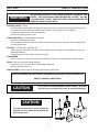
WELDING AND PLASMA CUTTING CAN BE INJURIOUS TO YOURSELF AND
OTHERS. TAKE PRECAUTIONS WHEN WELDING OR CUTTING. ASK FOR
YOUR EMPLOYER’S SAFETY PRACTICES WHICH SHOULD BE BASED ON
MANUFACTURERS’ HAZARD DATA.
ELECTRIC SHOCK - Can kill.
- Install and earth (ground) the welding or plasma cutting unit in accordance with applicable standards.
- Do not touch live electrical parts or electrodes with bare skin, wet gloves or wet clothing.
- Insulate yourself from earth and the workpiece.
- Ensure your working stance is safe.
FUMES AND GASES - Can be dangerous to health.
- Keep your head out of the fumes.
- Use ventilation, extraction at the arc, or both, to take fumes and gases away from your breathing zone
and the general area.
ARC RAYS - Can injure eyes and burn skin.
- Protect your eyes and body. Use the correct welding / plasma cutting screen and lter lens and wear
protective clothing.
- Protect bystanders with suitable screens or curtains.
FIRE HAZARD
- Sparks (spatter) can cause re. Make sure therefore that there are no inammable materials nearby.
NOISE - Excessive noise can damage hearing.
- Protect your ears. Use earmus or other hearing protection.
- Warn bystanders of the risk.
MALFUNCTION - Call for expert assistance in the event of malfunction.
READ AND UNDERSTAND THE INSTRUCTION MANUAL BEFORE INSTALLING OR OPERATING.
PROTECT YOURSELF AND OTHERS!
WARNING
This product is solely intended for plasma cutting. Any other
use may result in personal injury and / or equipment damage.
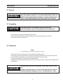
CAUTION
CAUTION
To avoid personal injury and/or equipment
damage, lift using method and attachment
points shown here.

9
SECTION 2 DESCRIPTION
2.1 Introduction
The EPP power source is designed for marking and high speed plasma mechanized cutting applications. It can
be used with other ESAB products such as the PT-15, PT-19XLS, PT-600 and PT-36 torches along with the Smart
Flow II, a computerized gas regulation and switching system.
• 10 to 100 amperes for marking in low current range
• 50 to 450 amperes cutting in high current range
• 35 to 100 amperes cutting in low current range
• Forced air cooled
• Solid state DC power
• Input voltage protection
• Local or remote front panel control
• Thermal switch protection for main transformer and power semiconductor components
• Top lifting rings or base forklift clearance for transport
• Parallel supplemental power source capabilities to extend current output range.
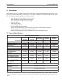
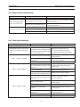
2.2 General Specications
EPP-450 Input/Output Information
Part Number
EPP-450
380V 50/60HZ
380V TAPS
EPP-450
380V 50/60HZ
400V TAPS
EPP-450
400V 50/60HZ
EPP-450
460V 60HZ
EPP-450
575V 60HZ
0558007730 0558007731 0558007732
Input Voltage (3-Phase) 380VAC 380VAC 400VAC 460VAC 575VAC
Input Current (3-Phase) 167A RMS 167A RMS 159A RMS 138A RMS 110A R M S
Input Frequency 50/60 HZ 50/60 HZ 50/60 HZ 60 HZ 60 HZ
Input KVA 109.9 KVA 109.9 KVA 110.2 KVA 110.0 KVA 109.6 KVA
Input Power 98.9 KW 98.9 KW 99.1 KW 99.0 KW 98.6 KW
Input Power Factor 90% 90% 90% 90% 90%
Recommended Input
Power Cable
*2/0 AWG *2/0 AWG *2/0 AWG *1/0 AWG *2/0 AWG
Input Fuse (Recommended) 200A 200A 200A 200A 150A
Output Open Circuit Voltage
(OCV) (High Range Cutting)
430VDC 406VDC 427VDC 431VDC 431VDC
Output Open Circuit Voltage
(OCV) (Low Range Cutting)
414VDC 393VDC 413VDC 415VDC 415VDC
Output Open Circuit Voltage
(OCV) (Marking)
360VDC 342VDC 369VDC 360VDC 360VDC
Output Cutting High Range
(100% Duty)
50A @ 100V TO 450A @ 200V
Output Cutting Low Range
(100% Duty)
35A @ 94V TO 100A @ 120V
Output Marking Low Range
(100% Duty)
10A @ 84V TO 100A @ 120V
Output Power (100% Duty) 90 KW
* Fuse sizes per National Electrical Code for a 90° C (194˚ F) rated copper conductors @ 40° C (104˚ F) ambient. Not more
than three conductors in raceway or cable. Local codes should be followed if they specify sizes other than those listed
above.

10
SECTION 2 DESCRIPTION
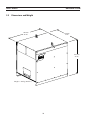
2.3 Dimensions and Weight
Weight = 850 kg. (1870 lbs.)
1143 mm
45.00”
946 mm
37. 2 5”
1022 mm
40.25”

11
SECTION 3 INSTALLATION
3.1 General
FAILURE TO FOLLOW INSTRUCTIONS COULD LEAD TO DEATH, IN
JURY OR DAMAGED PROPERTY. FOLLOW THESE INSTRUCTIONS TO
PREVENT INJURY OR PROPERTY DAMAGE. YOU MUST COMPLY WITH
LOCAL, STATE AND NATIONAL ELECTRICAL AND SAFETY CODES.
WARNING
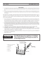
3.2 Unpacking
Using one lifting eye will damage sheet metal and frame.
Use both lifting eyes when transporting with overhead method.
CAUTION
• Inspect for transit damage immediately upon receipt.
• Remove all components from shipping container and check for loose parts in container.
• Inspect louvers for air obstructions.
3.3 Placement
Note:
Use both lifting eyes when transporting from overhead.
• A minimum of 1 M (3 ft.) clearance on front and back for cooling air ow.
• Plan for top panel and side panels having to be removed for maintenance, cleaning and inspection.
• Locate the EPP-450 relatively close to a properly fused electrical power supply.
• Keep area beneath power source clear for cooling air ow.
• Environment should be relatively free of dust, fumes and excessive heat. These factors will aect cool-
ing eciency.
Conductive dust and dirt inside power source may cause arc ash-
over.
Equipment damage may occur. Electrical shorting may occur if dust is
allowed to build-up inside power source. See maintenance section.
CAUTION
CAUTION

12
SECTION 3 INSTALLATION
3.4 Input Power Connection
ELECTRIC SHOCK CAN KILL!
PROVIDE MAXIMUM PROTECTION AGAINST ELECTRICAL SHOCK.
BEFORE ANY CONNECTIONS ARE MADE INSIDE THE MACHINE, OPEN
THE LINE WALL DISCONNECT SWITCH TO TURN POWER OFF.
WARNING
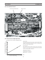
3.4.1 Primary Power
EPP-450 is a 3-phase unit. Input power must be provided from a line (wall) disconnect switch that contains fuses
or circuit breakers in accordance to local regulations.
Dedicated power line may be necessary.
EPP-450 is equipped with line voltage compensation but to avoid
impaired performance due to an overloaded circuit, a dedicated
power line may be required.
NOTICE
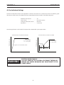
Input current =
(V arc) x (I arc) x 0.688
(V line)
To estimate the input current for a wide range of output conditions, use the formula below.
Note:
Please refer to table under “General Specications” in Subsection 2.2 for recommended cable and input fuse sizes.

13
• Customer supplied
• May consist either of heavy rubber covered copper conductors (three power and one ground) or run
in solid or exible conduit.
• Sized according to the table under “General Specications” in Subsection 2.2.
3.4.2 Input Conductors
Input conductors must be terminated with ring terminals.
Input conductors must be terminated with ring terminals sized for
12.7 mm (0.50”) hardware before being attached to the EPP-450.
NOTICE
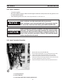
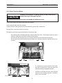
1. Remove left side panel of the EPP-450
2. Thread cables through the access opening in the rear panel.
3. Secure cables with a strain relief at the access opening.
4. Connect the ground lead to the stud on the chassis base.
5. Connect the power lead ring terminals to the primary termi-
nals with supplied bolts, washers and nuts.
6. Connect the input conductors to the line (wall) disconnect.
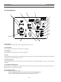
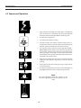
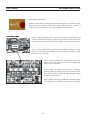
3.4.3 Input Connection Procedure
1
3
2
1 = Primary Terminals
2 = Chassis Ground
3 = Power Input Cable Access Opening (Rear Panel)
SECTION 3 INSTALLATION
Inspect the clearance between the power lead ring terminals and the
side panel. The barrels of some large terminals can come very close
to or touch the side panel if the terminal is mounted incorrectly. The
barrels of the terminals mounted on TB4 and TB6 should be rotated
to face away from the side panel.
CAUTION

14
ELECTRIC SHOCK CAN KILL!
RING TERMINALS MUST HAVE CLEARANCE BETWEEN SIDE PANEL
AND MAIN TRANSFORMER. CLEARANCE MUST BE SUFFICIENT TO
PREVENT POSSIBLE ARCING. MAKE SURE CABLES DO NOT INTER
FERE WITH COOLING FAN ROTATION.
IMPROPER GROUNDING CAN RESULT IN DEATH OR INJURY.
CHASSIS MUST BE CONNECTED TO AN APPROVED ELECTRICAL
GROUND. BE SURE GROUND LEAD IS NOT CONNECTED TO ANY PRI
MARY TERMINAL.
ELECTRIC SHOCK CAN KILL! DANGEROUS VOLTAGE AND CURRENT!
ANY TIME WORKING AROUND A PLASMA POWER SOURCE WITH COV
ERS REMOVED:
• DISCONNECT POWER SOURCE AT THE LINE (WALL) DISCONNECT.
• HAVE A QUALIFIED PERSON CHECK THE OUTPUT BUS BARS (POSI-
TIVE AND NEGATIVE) WITH A VOLTMETER.
3.5 Output Connections
WARNING
WARNING
WARNING
3.5.1 Output Cables (customer supplied)
Choose plasma cutting output cables (customer supplied) on the basis of one 4/0 AWG, 600 volt insulated cop-
per cable for each 400 amps of output current. For 450 amps, 100% duty cutting, two parallel 2/0 AWG, 600 volt
cables should be used.
Note:
Do not use 100 volt insulated welding cable.
SECTION 3 INSTALLATION
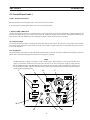
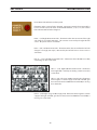
3.5.2 Output Connection Procedure - Single Power Source
1. Remove access panel on the lower front of the power source.
2. Thread output cables through the openings at the bottom of the front panel or at the bottom of the power source im-
mediately behind the front panel.
3. Connect cables to designated terminals mounted inside the power source using UL listed pressure wire connectors.
4. Replace panel removed during the rst step.

15
SECTION 3 INSTALLATION
Open Access Panel
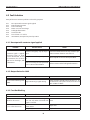
Two EPP-450 power sources may be connected together in parallel to extend the output current range.
3.6 Parallel Installation
CAUTION
Use only one power source for cutting below 100A.
We recommend disconnecting the negative lead from the supple-
mental power source when changing to currents below 100A. This
lead should be safely insulated to protect against electric shock.
Power Source
pilot arc
* 2 - 2/0 AWG 600V
positive leads
to workpiece
1 - 14 AWG 600V
lead to pilot arc con-
nection in arc starter
box (h.f. generator)
EPP-450
work
(+)
electrode
(-)
* Two parallel 2/0 AWG leads are recommended for
450A 100% duty operation. For operation at or below
400A 100% duty, one 4/0 lead may be used. Also, for
450A operation at or below 80% duty, one 4/0 lead
may be used. 80% maximum duty means operation
for no more than 8 minutes in any 10 minute time in-
terval.
* 2 - 2/0 AWG
600V
negative leads
in arc starter box
(h.f. generator)

16
SECTION 3 INSTALLATION
Note:
Primary power source has the electrode (-) conductor jumpered. The supplemental power source has the
work (+) jumpered.
1. Connect the negative (-) output cables to the arc starter box (high frequency generator).
2. Connect the positive (+) output cables to the workpiece.
3. Connect the positive (+) and negative (-) conductors between the power sources.
4. Connect the pilot arc cable to the pilot arc terminal in the primary power source. The pilot arc connection in the supple-
mental power source is not used. The pilot arc circuit is not run in parallel.
5. Set the Pilot Arc HIGH / LOW switch on the supplemental power source to “LOW”.
6. Set the Pilot Arc HIGH / LOW switch on the primary power source to “HIGH”.
7. If a remote 0.00 to +10.00 VDC current reference signal is used to set the output current, feed the same signal into both
power sources. Connect J1-G (positive 0.00 to 10.00 VDC) of both power sources together and connect J1-P (negative)
of both power sources together. With both power sources operating, the output current can be predicted using the
following formula: [output current (amps)] = [reference voltage] x [100]
ELECTRIC SHOCK CAN KILL!
EXPOSED ELECTRICAL CONDUCTORS CAN BE HAZARDOUS!
DO NOT LEAVE E LECTRICALLY “HOT“ CO NDUC TORS EXPOSE D. WHEN
DISCONNECTING THE SUPPLEMENTAL POWER SOURCE FROM THE
PRIMARY, VERIFY THE CORRECT CABLES WERE DISCONNECTED. IN
SULATE THE DISCONNECTED ENDS.
WHEN USING ONLY ONE POWER SOURCE IN A PARALLEL CONFIGU
RATION, THE NEGATIVE ELECTRODE CONDUCTOR MUST BE DIS
CONNECTED FROM THE SUPPLEMENTAL POWER SOURCE AND THE
PLUMBING BOX. FAILURE TO DO THIS WILL LEAVE THE SUPPLEMEN
TAL ELECTRICALLY “HOT”.
WARNING
DO NOT OPERATE THE EPP450 WITH COVERS REMOVED.
HIGH VOLTAGE COMPONENTS ARE EXPOSED INCREASING SHOCK
HAZARD.
INTERNAL COMPONENT MAY BE DAMAGED BECAUSE COOLING FANS
WILL LOSE EFFICIENCY.
The EPP-450 does not have an ON/OFF switch. The main power is controlled through the line (wall) disconnect switch.
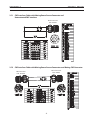
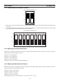
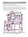
3.6.1 Connections for Two EPP-450’s in Parallel

17
SECTION 3 INSTALLATION
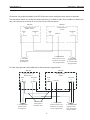
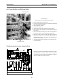
The connections below are suitable for parallel operation up to 800A at 100% duty or 900A at or below 80%
duty. 80% duty means 8 minutes of arc “on” time in any 10 minute period.
Supplemental
Power Source
Primary Power
Source
work
(+)
electrode
(-)
pilot arc
3 - 2/0 AWG 600V
positive leads
to workpiece
1 - 14 AWG 600V
lead to pilot arc con-
nection in arc starter
box (h.f. generator)
3 - 2/0 AWG 600V
negative leads
in arc starter box
(h.f. generator)
EPP-450 EPP-450
work
(+)
electrode
(-)
2/0 AWG 600V
cable jumpers
between units
Supplemental
Power Source
Primary Power
Source
work
(+)
electrode
(-)
pilot arc
2 - 4/0 600V
positive leads
to workpiece
1 - 14 AWG 600V
lead to pilot arc con-
nection in arc starter
box (h.f. generator)
2 - 4/0 600V
negative leads
in arc starter box
(h.f. generator)
EPP-450 EPP-450
work
(+)
electrode
(-)
Connections for parallel installation of two EPP-450 power sources with both power sources in operation.
For 100% duty operation above 800A refer to the connection diagram below.

18
SECTION 3 INSTALLATION
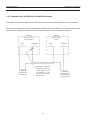
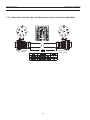
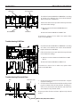
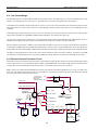
Connections for parallel installation of two EPP-450 power sources with only one power source in operation.
Connections for single power source operation up to 400A, 100% duty or 450A up to a maximum of 80% duty.
Maximum 80% duty means operation for no more than 8 minutes in any 10 minute time interval.
Supplemental
Power Source
Primary Power
Source
work
work
electrode
electrode
2 - 4/0 600V
positive leads
to workpiece
2 - 4/0 600V
negative leads
in arc starter box
(h.f. generator)
Disconnect negative
connection from sec-
ondary power source
and insulate to con-
vert from two to one
power source
EPP-450 EPP-450
3.6.1 Connections for Two EPP-450’s in Parallel (continued)

19
SECTION 3 INSTALLATION
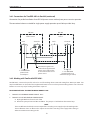
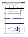
The connections below are suitable for single power supply operation up to 450A up to 100% duty.
Supplemental
Power Source
Primary Power
Source
work
work
electrode
electrode
3 - 2/0 AWG 600V
positive leads
to workpiece
3 - 2/0 AWG 600V
negative leads in arc
starter box (h.f. generator)
Disconnect negative con-
nection from supplemental
power source and insulate
to convert from two to one
power source
EPP-450 EPP-450
3.6.1 Connections for Two EPP-450’s in Parallel (continued)
Connections for parallel installation of two EPP-450 power sources with only one power source in operation.
Two EPP-450’s, connected in parallel, and can be used for marking down to 20A and cutting from 100A up to 900A. Two
simple modications can be made to the Supplemental Power Source in order to permit marking down to 10A. The modi-
cations are necessary only if marking below 20A is required.
FIELD MODIFICATIONS TO PERMIT MARKING DOWN TO 10A:
1. CHANGES TO THE PRIMARY POWER SOURCE: None
2. CHANGES TO THE SUPPLEMENTAL POWER SOURCE:
A. Unplug the WHT wire from the coil of K12
B. Remove the jumper between TB7-7 and TB7-8. The jumper is a link built into the terminal strip.
NOTE:
These modications disable the current output of the secondary power supply only in the marking mode.
The modications have no eect on the output current of the secondary power supply while cutting in
either HI or LOW current cutting modes.
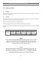
3.6.2 Marking with Two Parallel EPP-450’s

20
SECTION 3 INSTALLATION
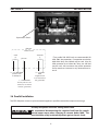
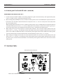
3.7 Interface Cables
CNC Interface (24 Conductors)
3.6.2 Marking with Two Parallel EPP-450’s (continued)
Water Cooler Interface (8 Conductors)
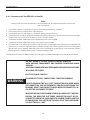
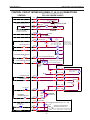
OPERATION OF TWO PARALLEL EPP-450’S:
1. Provide Contactor On/O, Cut/Mark, Current Range High/Low signals to both the Primary and Supplemental power
sources. Feed the same V
REF
signal into both power sources.
2. When marking with parallel power sources, and the Secondary power source is not modied, the output current trans-
fer function is the sum of the transfer functions for each power source: I
OUT
= 20 x V
REF
. Each power source will provide
the same output current.
When marking with parallel power sources, and the Secondary power source is modied, the current transfer function
is that of the Primary power source: I
OUT
= 10 x V
REF
. Both power sources will turn on when the Contactor signal is pres-
ent, but the output current of a modied Secondary power source is disabled in the marking mode.
3. When cutting in the Low current mode, the current transfer function is the sum of the transfer functions for each
power source: I
OUT
= 20 x V
REF
. For cutting at currents below 100A, disconnect the negative cable(s) from the secondary
power source, and insure their terminations are insulated to protect against electric shock. With the secondary power
source disconnected, the current transfer function is that of the Primary power source: I
OUT
= 10 x V
REF
.
4. When cutting in the High current mode, the current transfer function is the sum of the transfer functions for each
power source: I
OUT
= 100 x V
REF
. For cutting at currents below 100A, disconnect the negative cable(s) from the second-
ary power source, and insure their terminations are insulated to protect against electric shock. Use the Low current
cutting mode.
Page is loading ...
Page is loading ...
Page is loading ...
Page is loading ...
Page is loading ...
Page is loading ...
Page is loading ...
Page is loading ...
Page is loading ...
Page is loading ...
Page is loading ...
Page is loading ...
Page is loading ...
Page is loading ...
Page is loading ...
Page is loading ...
Page is loading ...
Page is loading ...
Page is loading ...
Page is loading ...
Page is loading ...
Page is loading ...
Page is loading ...
Page is loading ...
Page is loading ...
Page is loading ...
Page is loading ...
Page is loading ...
Page is loading ...
Page is loading ...
Page is loading ...
Page is loading ...
Page is loading ...
Page is loading ...
Page is loading ...
Page is loading ...
Page is loading ...
Page is loading ...
Page is loading ...
Page is loading ...
Page is loading ...
Page is loading ...
Page is loading ...
Page is loading ...
Page is loading ...
Page is loading ...
Page is loading ...
Page is loading ...
-
 1
1
-
 2
2
-
 3
3
-
 4
4
-
 5
5
-
 6
6
-
 7
7
-
 8
8
-
 9
9
-
 10
10
-
 11
11
-
 12
12
-
 13
13
-
 14
14
-
 15
15
-
 16
16
-
 17
17
-
 18
18
-
 19
19
-
 20
20
-
 21
21
-
 22
22
-
 23
23
-
 24
24
-
 25
25
-
 26
26
-
 27
27
-
 28
28
-
 29
29
-
 30
30
-
 31
31
-
 32
32
-
 33
33
-
 34
34
-
 35
35
-
 36
36
-
 37
37
-
 38
38
-
 39
39
-
 40
40
-
 41
41
-
 42
42
-
 43
43
-
 44
44
-
 45
45
-
 46
46
-
 47
47
-
 48
48
-
 49
49
-
 50
50
-
 51
51
-
 52
52
-
 53
53
-
 54
54
-
 55
55
-
 56
56
-
 57
57
-
 58
58
-
 59
59
-
 60
60
-
 61
61
-
 62
62
-
 63
63
-
 64
64
-
 65
65
-
 66
66
-
 67
67
-
 68
68


ESAB EPP-450 Plasma Power Source User manual
- Category
- Welding System
- Type
- User manual
Ask a question and I''ll find the answer in the document
Finding information in a document is now easier with AI
Related papers
-
ESAB EPP-450 Plasma Power Source User manual
-
ESAB EPP-450 Precision Plasma Power Source User manual
-
ESAB EPP-450 User manual
-
ESAB EPP-400 Plasma Power Source User manual
-
-
-
ESAB EPP-600 Plasma Power Source User manual
-
-
-
Other documents
-
TOA B-21S Specification Data
-
 Top Gun CUT 65 CNC User manual
-
AOpen AK33 M Online Manual
-
 SKB 3-4250 User manual
-
 Baldor-Reliance DC Injection Brake Connection Diagram Owner's manual
-
Legrand Lighting Integrator Panel Installation guide
-
Cebora 956 Plasma Prof 123 ACC User manual
-
 Buildbotics CNC Controller Quick start guide
-
 Altec Lansing 1590E User manual
-
Oriental motor MDV420-24S Owner's manual


