Page is loading ...

Motor PTC Kit
Kit PTC del Motor
Kit PTC do Motor
SSW-07 / SSW-08
Installation, Configuration and Operation Guide
Guía de Instalación, Configuración y Operación
Guia de Instalação, Configuração e Operação
English / Español / Português
Motors | Automation | Energy | Transmission & Distribution | Coatings

3
1. Description of the Kit ...................................................5
2. Safety Notices .............................................................5
3. Optional Module Description ......................................5
4. Motor PTC Kit Installation Procedure .............................6
1. Descripción del Kit ...................................................... 8
2. Informaciones de Seguridad.........................................8
3. Descripción Del Opcional ............................................8
4. Procedimiento para La Instalación del Kit PTC del Motor ..9
1. Descrição do Kit .........................................................11
2. Informações de Segurança ..........................................11
3. Descrição do Opcional ...............................................11
4. Procedimento Para Instalação do Kit PTC do Motor .........12

5
Contents:
Table 1 - Contents of the kit
Switch off the soft-starter SSW-07/SSW-08 before installing the motor
PTC kit.
The electronic boards have components that are susceptible to electrostatic
discharge. Never touch any of the electrical components or connectors
without following the proper grounding procedures. If it is necessary to do
so, touch the grounded heatsink or use a suitable grounded wrist strap.
This optional module allows the connection of the motor thermistor to the
soft-starter.
The motor PTC kit is connected directly to the soft-starter. It is fitted into the
front cover slot for optional plug-in modules.
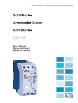
The tables 2 and 3 present information on the actuation level and the terminal
strip description respectively.
Table 2 - Actuation level specification
Table 3 - Terminal strip description
SSW-07/SSW-08 motor PTC kit (Part number: 10413867)
Quantity Description
1 Motor PTC optional plug-in module
Description of the motor PTC kit connector
Terminal Description
1 Not connected
2 PTC A
3 PTC B
4 Not connected
Motor PTC actuation level specication
Error trip: 3k9 Release: 2k4
Minimum resistance: 80 Ω
ENGLISH

6
Figure 1 - PTC actuation
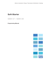
1. Contents of the kit.
2. Take out the optional plug-in cover.
Inactive /
Without error
Inactive /
Without error
Active / E32
Inactive /
Without error
Active / E32Active / E32
Temperature
decrease
2k4 3k9
Temperature
increase
PTC resistance
change in ohms (Ω)
PTC
XC44:
Motor PTC
kit
3
2
ENGLISH

7
3. Replace the cover with the optional plug-
in module. Make sure that the module be
connected.
4. Connect the motor PTC in the pins 2 and
3 of the optional module with the cable
terminals below, according to the figure.
ENGLISH
/