WEG SSW06 User guide

Type
User guide
Soft-Starter
Arrancador Suave
Soft-Starter
Sanftanlaufgeräts
Démarreur Progressif
Avviatori Statici
SSW06
Motors | Automation | Energy | Transmission & Distribution | Coatings
Installation Guide
Guía de Instalación
Guia de Instalação
Kurze Installationsanleitung
Guide Rapide D’Installation
Guida di Installazione
ENGLISHESPAÑOLPORTUGUÊSDEUTSCHFRANÇAISITALIANO
Installation Guide
Series: SSW06
Document no.: 10001069241 / 00
Publication date: 03/2011
1
SSW06 Installation Guide Page 5
ENGLISH
ENGLISH
SSW06 QUICK INSTALLATION GUIDE
SAFETY NOTICES
DANGER!
Only qualified personnel should plan or implement the
installation, start-up, operation and maintenance of this
equipment.
These personnel must follow all safety instructions
included in the manuals of the product and/or defined by
local regulations.
Failure to comply with these instructions may result in
personal injury and/or equipment damage.
NOTE!
In this guide, qualified personnel are defined as people
that are trained to:
Install, ground, power-up and operate the SSW06
according to the manuals of the product and the
local required safety procedures.
Use of safety equipment according to the local
regulations.
Administer First Aid Treatment.
DANGER!
Always disconnect the main power supply before
touching any electrical component associated with the
SSW06.
High voltages and spinning parts (fans) may be present
even after switching off the power supply. Wait at least
3minutes for the complete discharge of the capacitors
and until the fans stopped.
Always connect the equipment frame to the protection
earth (PE) in the appropriate place for this.
ATTENTION!
All electronic boards have components that are sensitive
to electrostatic discharges. Never touch any of the
electrical components or connectors.
If necessary to do so, touch the properly grounded
metallic frame or use a suitable ground strap.
DANGER!
Do not apply a high voltage (High Pot) test on the
SSW06! If this test is necessary, contact the
manufacturer.
RECEIVING AND STORAGE
When receiving the product verifies if:
The SSW06 nameplate data matches the purchase order;
The equipment has not been damaged during transportation. If
any problem is detected, contact the carrier immediately.
If the SSW06 is not to be installed immediately, store it within
its original cardboard box in a clean and dry room (Storage
temperatures between -25°C (-13°F) and 65°C (149°F).
MECHANICAL INSTALLATION
The SSW06 must be mounted in a free environment of:
Direct exposure to sunlight, rain, excessive moisture or marine
environment;
Explosive or corrosive gases and liquids;
Excessive vibration, dust or metallic and/or oil particles in the air.
Allowed Environment Conditions:
Temperature: 0ºC to 55ºC (32ºF to 131ºF) – models 10A to 820A;
0ºC to 40ºC (32ºF to 104ºF) – models 950A to 1400A.
Relative Air Moisture: 5%to 90%, non-condensing.
Degree of Pollution: 2 (according to UL508).
More details to see User´s Guide – Chapter 3 - Item 3.1.1 -
Environment Conditions.
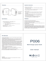
Positioning and Fixing:
Free spaces for cooling air flow must be left open around the SSW06,
as shown.
Model
A
mm(in)
B
mm(in)
C
mm(in)
Y
mm(in)
SSW06.0010
to
SSW06.0950
150
(5,90)
30 (1,18)
150
(5,90)
50 (1,96)
SSW06.1100
and
SSW06.1400
150
(5,90)
100
(3,93)
150
(5,90)
50 (1,96)
Install the SSW06 on a flat surface.
Do not place heat sensitive components above the SSW06.
ATTENTION!
Foresee independent conduits or electroducts for
physically separating the signal, control and power
conductors
Provide at least a 0.25m (10 in) space between sensitive
equipment and wiring from the SSW06, and the cables
between the SSW06 and the motor.
SSW06 Installation GuidePage 6
ENGLISH
Mounting inside a Panel:
When the SSW06 are installed in panels or closed metallic boxes,
adequate cooling is required to ensure that the temperature around the
SSW06 will not exceed the maximum allowed temperature [see User´s
Guide – Chapter 3 – item 3.1.3.1 – Mounting inside a Panel – Tables
3.3 and 3.5].
Mounting on a Surface:
Installation of the SSW06 on a mounting plate
First install and partially tighten the mounting bolts, then install the
SSW06 and tighten the mounting bolts.
External dimensions, mounting screws and weight of the SSW06 are
shown in the User´s Guide - Chapter 3 - Item 3.1.2 - Dimensions of the
SSW06.
Procedures for HMI removal and front cover opening for the control
connections exposure.
ELECTRICAL INSTALLATION
DANGER!
Be sure that the AC input power is disconnected before
making any terminal connections.
ATTENTION!
The described information in manuals of the SSW06
have the intention to serve as guide to get a correct
installation. It also follows all applicable local standards
for electrical installations.
DANGER!
The SSW06 cannot be used as an emergency stop
device.
Power Terminals:
The power connection terminals can be of different sizes and
configurations, depending of the SSW06 model [see User´s Guide
– Chapter 3 – Item 3.2.1 – Power Terminals – Figures 3.8x – Power
Terminals, Table 3.5 – Maximum tightening Torque for power
connection and Figures 3.9x – Location of the connections].
R / 1L1, S / 3L2 and T / 5L3: AC power supply line.
U / 2T1, V / 4T2 and W / 6T3: Motor connection.
Power and Grounding Cables:
NOTE!
For correct cable sizing, consider the installation
condition, the maximum permitted line voltage drop, and
follow electrical instructions defined by local regulations.
For more details: see User´s Guide – Chapter 3 – Item 3.2.3 –
Recommended Power and Grounding Cables – Tables 3.6 e 3.7.
Connection of the Power Supply to the SSW06:
DANGER!
The supply voltage must be compatible with the nominal
voltage of the SSW06. Models of 220 to 575 Vac or the
models of 575 to 690 Vac.
DANGER!
Provide a power supply disconnecting switch. This
disconnecting switch must disconnect the AC input
voltage from the SSW06, when ever required (for
instance during maintenance services).
Power Supply Capacity [see User´s Guide – Chapter 3 – Item 3.2.4.1. –
Power Supply Capacity].
Recommended Fuses [see User´s Guide – Chapter 3 – Item 3.2.4.2. –
Recommended Fuses].
1
SSW06 Installation Guide Page 7
ENGLISH
Connection of the SSW06 to the motor:
DANGER!
Power factor correction capacitors should never be
connected to the output of the SSW06 (U / 2T1, V / 4T2
and W / 6T3).
ATTENTION!
The nominal current of the motor cannot be lower than
30% of the nominal current of the SSW06.
Types of connection to the motor:
Standard Connection of the SSW06 to the Motor with Three Cables
(P150=0=Inactive)
Inside Delta Motor Connection of the SSW06 with Six Cables
(P150=1=Active)
ATTENTION!
Pay attention to the connection of the motor to the
SSW06, respect the connection diagrams shown in
User´s Guide – Chapter 3 – Item 3.2.5 - Connection of
the SSW06 to the motor.
If it is necessary to change the motor rotating direction,
only invert the SSW06 connections to the power supply,
when the inside delta motor connection will be used.
DANGER!
The inside delta motor connection cannot be used in line
voltage higher than 575Vac.
DANGER!
Ensure correct setting of Parameter P150 before the
motor is switched ON. SSW06 may be damaged, when
this parameter setting is not correct.
Grounding Connections:
DANGER!
The SSW06 must be grounded for safety purposes (PE).
The earth or ground connection must comply with the
local regulations. (resistance ≤ 10 ohms).
ATTENTION!
The SSW06 can be used in power supply grounded of
the type TT or TN (IEC) or in power supply of the type IT,
since that grounded by an impedance.
DANGER!
Do not use the neutral conductor for grounding
purposes. Use a specific ground conductor.
For more details see User´s Guide – Chapter 3 – Item 3.2.6 –
Grounding Connections.
Fan Connections:
It’s available in models greater than 255A. The nominal voltage of the
fans can be selected by switch in models from 255A to 820A. For
models from 950A to 1400A the voltage selection is fixed, according to
the product specification.
For more details see User´s Guide – Chapter 3 – Item 3.2.7 – Fan
Connections.
Signal and Control Connections:
All the inputs and outputs of the SSW06 are programmable. The
details of the connections are available in the User´s Guide - Chapter 3 -
Item 3.2.8 - Signal and Control Connections.
DANGER!
Never apply high voltages to the digital inputs.
NOTE!
The auxiliary electronic power supply of the SSW06 of
+24Vdc shall only be used for the supply of the digital
inputs.
SSW06 Installation GuidePage 8
ENGLISH
RECOMMENDED SET-UPS
Recommend Set-ups with Command via Two-wire Digital Inputs.
P150=0, P220=1, P230=1, P263=1, P277=1, P279=6.
Recommend Set-ups with Command via Three-wire Digital Inputs and
Inside Delta Motor Connection.
P150=1, P220=1, P230=1, P263=2, P264=1, P277=1, P279=6.
NOTE!
For the protection of all of the electrical installation, the
use of fuses or circuit breakers in the main power supply
circuit is necessary.
The use of high speed semiconductor fuses are not
necessary for the functioning of the SSW06, but its use
is recommended for the complete protection of the
thyristors.
NOTE!
The transformer “T1” is optional and should be used
when the line voltage is different from the electronics and
fan voltage.
NOTE!
To protect the motor against destruction by possible
short circuits in the power circuit of the SSW06 use an
isolating contactor (K1) or circuit-breaker (Q1).
NOTE!
X1E (33 and 34) is only available on the models with
cooling fans.
NOTE!
For integral motor protection the installation of one or
more PTC (PTC at DI6) or thermostats (external fault at
DI4 to DI6) is recommended.
NOTE!
Remember that when a command via two-wire digital
input is used (the switch is normally open with retention),
every time the power supply returns, after any fault, the
motor starts immediately if the switch remains closed.
NOTE!
In case of maintenance services, remove the power
supply fuses or disconnect the power supply, thus
ensuring complete equipment disconnection from power.
NOTE!
An emergency stop can be obtained by disconnecting
the electronics power supply.
For more detail or others types of recommended set-ups see User´s
Guide – Chapter 3 – Item 3.3 – Recommended Set-ups.
1
SSW06 Installation Guide Page 9
ENGLISH
USE OF THE HMI
Programming keys:
Toggles the LED display between the parameter number
and its value (position / content).
Increases the number of the parameter or the value of the
parameter.
Decreases the number of the parameter or the value of the
parameter.
Command selecting keys:
Toggles between LOCAL or REMOTE modes of operation.
Parameter: P220 = 2 or 3.
NOTE!
In the factory default settings the commands for keys of
the HMI are enabling when the Local will be selected.
Command keys:
Enable the motor (start).
After starting, at each touch it commutates the fast access
indication on the display.
Disable the motor (stop).
It resets the SSW06 after a fault trip.
Reverses the motor direction of rotation. By contactor or
JOG Only.
Parameter: P231.
When the Jog key is pressed realize the Jog function (if the
motor is not enabled, the SSW06 is with General Enable
active and Jog is not enabled).
Parameters: P51X.
NOTE!
These functions can be executed via: digitals inputs,
communication serial, fieldbus or SoftPLC.
Parameters: P220, P229 and P230.
Parameter viewing and programming:
LED
Initial screen at power-up.
Press the key
.
Rdy
LCD
Soft-Starter
Ready
LED
Use the keys and .
Select the desired parameter.
P002
LCD
Motor Current
P002= 0.0%
LED
For example, change P101.
Press the key
.
P101
LCD
Init. Volt. Start
P101= 30%
LED
Value to be change.
30
LCD
Init. Volt. Start
P101= 30%
NOTE!
To allow the reprogramming of any parameter value it is
necessary to change parameter P000 to the password
value. The factory default password value is 5. Otherwise
you can only read the parameter values and not
reprogram them.
LED
Use the keys and change
the value of parameter.
35
LCD
Init. Volt. Start
P101= 35%
LED
Press the key and the value is
saved.
P101
LCD
Init. Volt. Start
P101= 35%
NOTE!
For parameters that can be changed with the motor
running, the SSW06 will use the new value immediately
after it has been set. For the parameters that can be
changed only with the motor stopped,
the SSW06 will use this new set value only after the key
is pressed with the motor disable.
NOTE!
If the last value programmed in the parameter is not
functionally compatible with other parameter values
already programmed, an E24 –Programming Error – will
be displayed.
SSW06 Installation GuidePage 10
ENGLISH
The parameters of the SSW06 can be grouped of the following form in accordance with its functions:
Measurements Indications Types of Control Inputs and Outputs Local / Remote
Current
P001, P002, P003,
P030, P031, P032
Voltage
P004, P007, P033,
P034, P035
Frequency
P005
Power Factor
P008
Torque
P009
Power
P010 and P011
KWh Consumed
P044 and P045
SSW Status
P006
DIs and DOs Status
P012 e P013
Analogs Outputs
P027 e P028
Thermal Class Status
P050
Selection
P202
Voltage Ramp
P10X
Current Limit
P11X
Torque Control
P12X
Pump Control
P13X
Digitals Inputs
P26X
Digitals Outputs
P27X
Analogs Outputs
P25X
Selection
P220
Local
P229
Remote
P230
Configurations of
the HMI
Configurations of
the SSW
Especial Function Communication Protections
Password
P000 e P200
Language
P201
Default Display
P205
Display Contrast
P218
Delta Inside
P150
External Bypass
P140
Auto-reset Time
P206
FWD/REV Selection
P231
Braking
P50X
Jog
P51X
Kick Start
P52X
Serial
P308, P312, P313
and P314
Fieldbus
P085,P309, P310,
P313, P315, P316
and P317
Voltage Protection
P60X
Current Protection
P61X
Phase Sequence
P620
Bypass Closed
P621
Timer After Stop
P630
Motor Thermal Class
P64X
Torque Protection
P65X
Power Protection
P66X
K-PT100 Protection
P67X, P68X and P69X
Error or Alarm Selection
P7XX
Data Backup Fault History Diagnostics SoftPLC
Software Version
P023
SSW´s Data
P29X
Motor´s Data
P40X
Load / Save
P204
Copy Function
P215
Last Errors
P014 a P019
Current, Voltage and
Status at Error
P06X and P07X
Current Fault
P020
Current Alarm
P021
Time Powered
P042
Time Enable
P043
Start
P047, P048, P049,
P058 and P059
Motor Enable
P053 to P057
Status
P088
Allows
P089
Enable
P950
Enable IOs Expansion
P951
User’s Parameters
P95X
For more details see the User´s Guide: Quick Parameter Reference – I. Parameters and II. Fault orAlarm Messages, Chapter 6 – Detailed Parameter
Description and Chapter 8 – Item 8.1 – Diagnostics and Troubleshooting.
1
SSW06 Installation Guide Page 11
ENGLISH
SSW06 Status:
LED
Soft-Starter is “ready” to be enabled.
Rdy
LCD
Soft-Starter
Ready
LED
Soft-Starter with fault.
Exx
LCD
Fault
description
LED
Soft-Starter with Alarm.
Axx
LCD
Alarm
description
NOTE!
These states are showed automatically on the display;
the others are showed in the parameterP006.
POWER-UP PREPARATION
DANGER!
Disconnect the AC power input before making any
connections.
Check if the power, grounding and control connections are correct
and well tightened.
Remove all shipping material from the inside of the SSW06 or
cabinet.
Check the correct voltage selection.
Check all motor connections and verify if their voltages, currents
and frequencies match the SSW06 specifications.
Check the SSW06 motor connection type. Check if the standard
three-wire connection should be used or if the SSW06 should be
connected via inside delta of the motor
Uncouple the load from the motor. If the motor cannot be
uncoupled, make sure that the direction of rotation (FWD/REV)
cannot cause damage to the machine.
Close the SSW06 and / or cabinet cover.
INITIAL POWER-UP
Check the supply voltage. Measure the line voltage and check if it
is within the specified range [see User´s Guide – Chapter 10 – Item
10.3 – Power Data and Item 10.4 – Electronics / Programming
Data].
Power-up the Electronics Supply.
ATTENTION!
In the first power-up, always energize the electronics
supply before energizing the power and program the
minimum necessary parameters to put the SSW06 in
functioning and later energizing the power.
Check if the power-up has been successful. When the SSW06 is
powered up for the first time or when the factory default parameter
values are loaded (P204 = 5), a start-up routine is run [see User´s
Guide – Chapter 5 – Figure 5.1 – Parameter sequence during initial
power-up].
This routine requests to the user who program some referring basic
parameters of the SSW06 and the motor:
Language [P201].
Type connection to the motor [P150].
Control type [Control Type].
Motor´s data [P40X].
Motor thermal class protection [P64X].
NOTE!
In this parameter setting sequence only the main
parameters for learning about the SSW06 operation are
shown.
ATTENTION!
For correct programming of the protection parameters,
please consider the catalog data and the motor
nameplate data of the used motor.
ATTENTION!
To protect the motor against overloads during the start
process and during operation, program the thermal class
of the motor.
Close the power input circuit-breaker.
Verify the power supply voltages through parameters P004, P033,
P034 and P035.
For more details of the start-up: see User´s Guide – Chapter 5 – Item
5.3 – Start-up.
For examples of programming of the types of control with different
types of loads, see User´s Guide – Chapter 7.
  • Page 1 1
  • Page 2 2
  • Page 3 3
  • Page 4 4
  • Page 5 5
  • Page 6 6
  • Page 7 7
  • Page 8 8
  • Page 9 9
  • Page 10 10
  • Page 11 11
  • Page 12 12
  • Page 13 13
  • Page 14 14
  • Page 15 15
  • Page 16 16
  • Page 17 17
  • Page 18 18
  • Page 19 19
  • Page 20 20
  • Page 21 21
  • Page 22 22
  • Page 23 23
  • Page 24 24
  • Page 25 25
  • Page 26 26
  • Page 27 27
  • Page 28 28
  • Page 29 29
  • Page 30 30
  • Page 31 31
  • Page 32 32
  • Page 33 33
  • Page 34 34
  • Page 35 35
  • Page 36 36
  • Page 37 37
  • Page 38 38
  • Page 39 39
  • Page 40 40
  • Page 41 41
  • Page 42 42
  • Page 43 43
  • Page 44 44
  • Page 45 45
  • Page 46 46

WEG SSW06 User guide

Type
User guide

Ask a question and I''ll find the answer in the document

Finding information in a document is now easier with AI