Electrolux GPWBOEOOBO (583284) User manual

Type
User manual
Thermetic
TILTING BOILING PANS, ROUND, ELECTRIC
(GU........, KU........)
TILTING FRYING PAN
(GP........)
US INSTALLATION INSTRUCTIONS
Doc. 62.9698.01
Edition 1
11.2003
62.9698.01 Page 1
CONTENTS
1. GENERAL REMARKS ........................................................................................................ 3
2. PACKAGING / TRANSPORT.............................................................................................. 3
3. TECHNICAL DATA / DIMENSIONED DRAWINGS / INSTALLATION PLANS ................. 3
3.1 TILTING BOILING PANS ................................................................................................................. 4
4. FLOOR GULLIES................................................................................................................ 5
5. MOUNTING / POSITIONING / FASTENING IN PLACE / ALIGNMENT............................. 6
5.1 Positioning ....................................................................................................................................... 6
5.2 ACCESS TO INSIDE THE CONSOLES AND SUPPORT ................................................................ 8
5.3 COVERS (PANELS) ......................................................................................................................... 8
6. INSTALLATION................................................................................................................... 9
6.1 ELECTRICAL CONNECTION........................................................................................................... 9
6.2 STEAM AND CONDENSATE CONNECTIONS ............................................................................. 11
6.3 UNIVERSAL CONTROL PARAMETER SETTINGS ...................................................................... 13
6.4 THERMACAM / HACCP ................................................................................................................. 17
6.5 INSPECTION PROCEDURES / TEST OF FUNCTIONS 1 ................................................................ 8
7. DECOMMISSIONING / DISMANTLING / DISPOSAL....................................................... 18
62.9698 Page 3
1. GENERAL REMARKS
Responsibility
The setting up, adjustment and initial commissioning of appli-
ances must be carried out in accordance with the manufac-
turer's instructions and may only be done by authorised
personnel. The installations for the electricity, steam, conden-
sate, hot water, gas and water supplies as well as ventilation
must be laid or fitted by approved installation contractors in
accordance with specific national and local regulations. The
installation contractors are responsible for the correct layouts
and installations in conformity with all safety regulations. The
warning signs and specification plates fitted to the appliances
must be strictly adhered to.
Validity
These instructions for installation refer to the THERMETIC tilt-
ing appliance program with appliances of different sizes: tilting
boiling pans, tilting braising pans and tilting pressure braising
pans.
Dimensioned drawings and installation plans of this document
are only for information purpose to the installers. These plans
may not be used for planning or projecting kitchens.
Tests/certificates
All electric appliances are tested by testing institutes. They ful-
fil standards UL 197 as well as NSF4 1999 and NSF 12 1992
(Chilltherm). The appliances are marked with the UL marking
on the specification plate.
2. PACKAGING / TRANSPORT
Types of packaging
Various types of packaging are used dependent on country of
destination. All versions of these appliances are transported
on a wooden frame or floor, are affixed to these with plastic
straps and located with wooden strips to prevent slipping.
Packaging markings
The external surfaces of the packaging have the following
markings which must be strictly adhered to:
Forwarding label with the following information:
- Delivery company
- Delivery company's order number
- Customer's order number if available
- Delivery address
- Package number
- Net weight in kg
- Gross weight in kg
- External dimensions of the packaging
Handling stickers with pictograms
- Umbrella = Keep dry; the packaged appliance
may not be stored outdoors
- Glass = Contents fragile
- Arrow pointing up = Only transport and store the
appliance in this position
- Stacking number = Number of appliances that can be
stacked (1 = cannot be stacked)
- Ice crystal and roof = Protect against frost
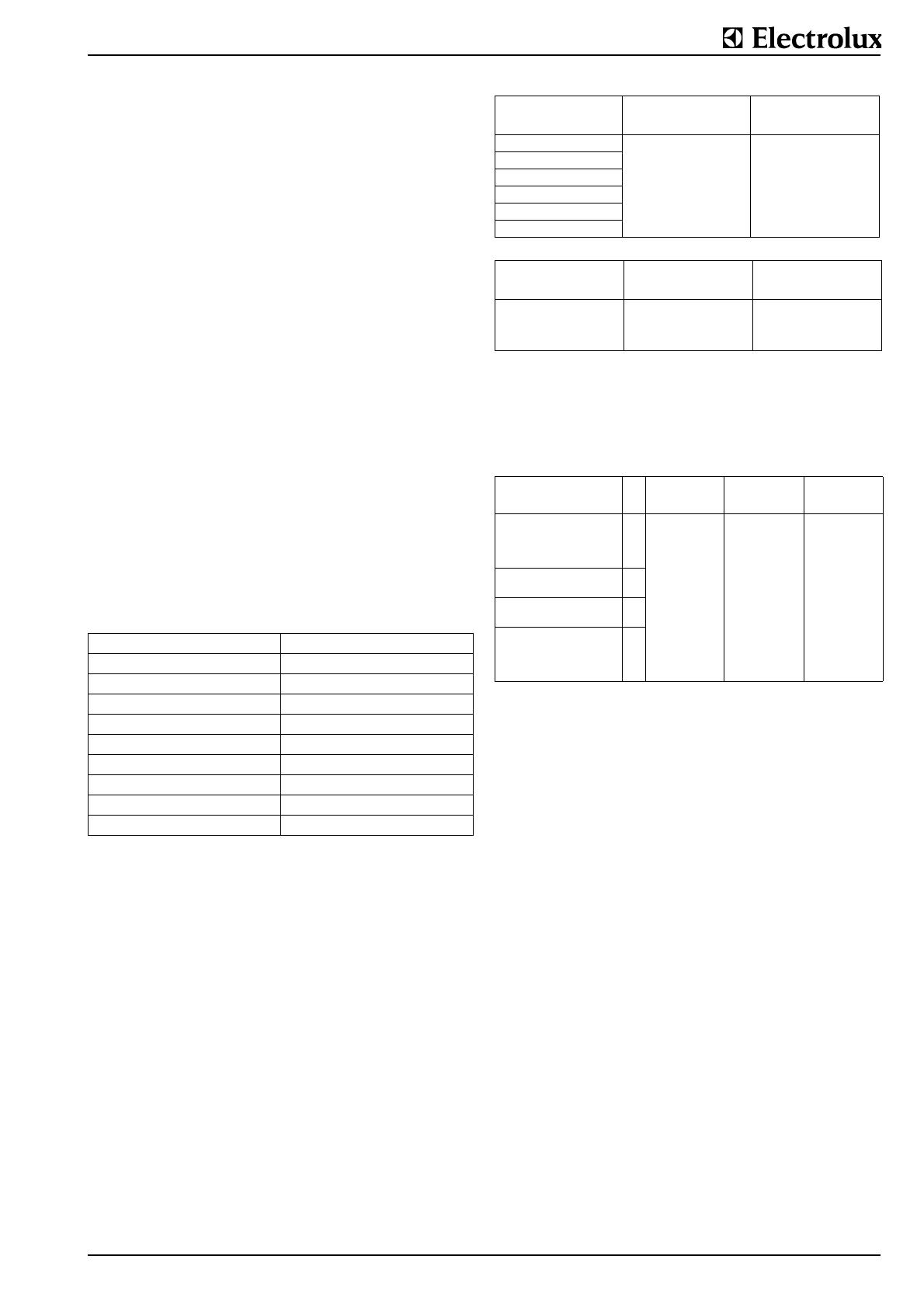
Transport weights
The precise gross and net weight is given on the forwarding
label. Due to the wide range of appliances, only the maximum
weights possible for the "European light" version are summa-
rized below:
Packaging dimensions
The precise external dimensions of the packaging are given on
the forwarding label attached to the outside of the packaging.
The maximum dimensions of the "European light" style of
packaging are given below:
(1) without floor support for wall mounting
(2) with floor support for floor mounting
Handling
Both packaged as well as unpacked appliances are best lifted
and transported whenever required with a pallet truck which is
inserted into the wooden frame or under the wooden base.
This applies to both the loading and unloading of trucks as well
as to handling operations on the installation site.
For handling by a crane, the unpacked appliances do not have
any specific lifting points to which they can be attached. It is
necessary to wrap two straps or ropes around the appliance
when lifting is required. Wrapping straps or ropes around the
appliance may only be done at the sides and not round the
front and the rear. The straps or ropes should be arranged
approximately 150 mm (5.9“) from the outer edges.
3. TECHNICAL DATA / DIMENSIONED DRAW-
INGS / INSTALLATION PLANS
These illustrations are not intended for the planning and laying
of the supply lines in the building.
Destination Overseas:
Version: Heavy, crate closed
Floor: Wooden floor
Floor fixing:
Side and cover frame:
Water and dust protection: Plastic film
Physical outer protection: Closed crate
Held together by: External steel banding
Transport: Forwarder
Stack ability: max. 4 appliances
Tilting boiling pans max. gross weight max. net weight
.U........ kg lb. kg lb.
080 LT (21.1 gal) 215 474 195 430
100 LT (26.4 gal) 250 551 230 507
150 LT (39.4 gal) 290 639 270 598
200 LT (52.8 gal) 380 838 360 794
300 LT (79.3 gal) 410 904 390 860
400 LT 105.7 gal) 450 992 420 960
Tilting braising pans max. gross weight max. net weight
.P........ kg lb. kg lb.
060 LT (15.9 gal) 230 507 210 463
080 LT (21.1 gal) 260 573 240 529
100 LT (26.4 gal) 290 639 270 595
Appliance size
LT
Width Depth Height
mm inch mm inch mm inch
Tilting boiling pans 80, 100
Tilting braising pans 60
Tilting pressure braising pans
60, 90
(1)
(2)
1400
1400
55.1
55.1
800
1200
31.5
47.2
1250
1100
49.2
43.3
Tilting boiling pans 150 (1)
(2)
1500
1500
59.1
59.1
1000
1300
39.4
51.2
1300
1100
51.2
43.3
Tilting boiling pans 200
Tilting braising pans 80
(1)
(2)
1600
1600
23.6
63
1100
1400
43.3
55.1
1400
1200
45.1
47.2
Tilting boiling pans 300, 400
Tilting braising pans100
Tilting pressure braising pans
100, 150
(1)
(2)
1700
1700
66.9
66.9
1100
1500
43.3
59.1
1500
1200
59.1
47.2
Page 4 62.9698
3.1 TILTING BOILING PANS
3.1.1 Electrically heated tilting boiling pans (.U........))
Additional loads are listed in 3.1.
Dimensioned drawings for tilting boiling pans (.U........)
L Length to floor gully
N Depth of floor gully
Installation plans for tilting boiling pans (.U........), tilting
frying pans (.P........), tilting braising pans (.X........)
Style of mounting (optional
Floor mounting with floor sup-
ports with consoles.
Tilting Motor tilting with lifting motor
Control system
PROCESS COMFORT con-
trol system with cooking tem-
perature control and
programmable cooking and
starting time.
Manual control for steam
heated boiling pans.
Stirring system (optional)
Grid stirrer with and without
scraper, blade stirrer.
Protective system hose proof IP X5
Net content in litres, max. capacity 80 - 400
Elect. motor tilting
Wattage in kW
Voltage (V), Current in A
0,1
230V/1~N,60 Hz, 0,7 A
Stirring system
Wattage in kW
Voltage (V), Current in A
0,37
208V/3~N, 60 Hz, 2.1 A,
240V/3~N, 60 Hz, 1.8 A
480V/3~N, 60 Hz, 0.9 A
CHILLTHERM
Wattage in kW,
Voltage ('), Current in A
0,4
208V/3~N, 60 Hz, 3.9 A,
240V/3~N, 60 Hz, 3.4 A,
480V/3~N, 60 Hz, 1.7 A
Heating 80 LT,
electric
100 LT,
electric
150 LT,
electric
200 LT,
electric
300 LT,
electric
400 LT,
electric
Wattage
kW
18,2 18,2 24,2 30,2 36,2 48,2
Voltage
208V/3~N
Current A
52 52 70 85.3 102 119
Voltage
240V/3~N
Current A
44 44 60 74.5 89 117.5
Voltage
480V/3~N
Current A
23 23 30 38 44.5 59
Fig. 1 Dimensioned drawings for tilting boiling pans
Pan size in litres
80 100 150 200 300 400
Dimensions mm
A
1200 1200 1300 1400 1500 1500
B
1073 1096 1124 1289 1352 1434
C
1034 1060 1090 1234 1290 1290
D
579 640 710 800 900 900
E
385 395 465 490 570 720
F
900 900 900 1900 900 900
G
476 450 420 376 320 3 20
H
80 88 97 110 110 110
J
680 680 680 780 780 780
K
900 900 900 1000 1000 1000
L
710 710 710 810 810 810
M
330 330 330 430 430 430
N
1000 1000 1000 1200 1200 1200
A Width of appliance (see
dimensioned drawing)
E Electrical cable protruding
from wall
V Steam or hot water supply,
Sandvik coupling, nominal
width 25 mm
R Condensate drain or hot
water return,
Y Sandvik-coupling, nomi-
nal width 25 mm
W Hot water connection G
1/2", NW15
K Cold water connection G
1/2", NW15
DKWater drain for steam con-
densation (.X........)
Fig. 2 Installation plans for tilting boiling pans, tilting
frying pans, tilting braising pans
62.9698 Page 5
Installation plans CHILLTHERM for tilting boiling pans
.U........
3.1.2 Directly steam-heated boiling pans (.U1......,
.U2......, .U3......, .U4......)
Tilting boiling pan with direct heating with saturated steam,
overpressure 0.8 bar (11.6 psi), temperature 244°F (118°C).
Voltage for the control and tilting systems: 230V/1~N, 60 Hz.
Stirring system see 3.1.
Dimensioned drawings see 3.1.1.
Installation plan for floor and wall mounting see 3.1.1.
3.1.3 TILTING FRYING PANS (.P........)
Model (optional) Pan bottom made of steel or chrome-nickel
plated steel
Style of mountingFloor mounting with floor support with con-
sole.
Tilting Motor tilting with lifting motor
Control system PROCESS COMFORT control system with
pan-base and cooking temperature control
and programmable cooking and starting
time.
Tilting Frying Pans
Dimensioned drawings
H Height for all types 900 mm (35.4“)
S Height of feet / wheel 200 mm (7.9“)
Installation plan see 3.1.1.
4. FLOOR GULLIES
In the case of tilting appliances, floor gullies with loose gratings
and floor drains which serve as drains when cleaning are pro-
vided for near to the outlet. Floor gullies can be designed for a
single appliance or for a whole group of appliances. There is a
very wide variety of types and sizes. Please consult the rele-
vant installation plans for information concerning layout and
type.
In general, the floor gullies with their drains are concreted into
the floor by the builder.
A Width of appliance (see
dimensioned drawing)
E Electrical cable protruding
from floor or wall
1 Mains supply
2 Potential free contact
3 Energie optimization
4 ThermaCam inlet
5 ThermaCam outlet
V Steam or hot water supply,
R Condensate drain or hot
water return
N Cooling water inlet
O Cooling water outlet
Z Sandvik-coupling, nominal
width 25 mm
W Hot water connection G
1/2", NW15
K Cold water connection G
1/2", NW15YConnection G
1/2"
S Steel or masonry plinth 100
- 200 mm
Fig. 3 Installation plan CHILLTHERM for tilting boiling
pans
Type 80 LT,
steam
100 LT,
steam
150 LT,
steam
200 LT,
steaS
300 LT,
steam
400 LT,
steam
External steam in
kg/h
40 48 63 77 100 122
Heating power in
kW
24,52938476175
Wattage in kW
Voltage Current in
A
0,20
120V/3~N, 60 Hz, 2.0 A,
208V/3~N, 60 Hz, 1.2 A,
240V/3~N, 60 Hz, 1.0 A,
480V/3~N, 60 Hz, 0.5 A
Type 060 LT,
electric
080 LT,
electric
100 LT,
electric
Dimension A (mm) 1200 1400 1600
(inch) 47.2 55.1 63
Braising surface (mm)
(inch)
Pan depth in (mm)
T(inch)
600 x 600
23.6x23.6
200
7.9
800 x 600
31.5
200
7.9
1000 x 600
39.8
200
7.9
Net content (litres)
(gal)
max. capacity
63
16.4
84
22.2
104
27.5
El. heating power in kW 12.2 15.2 18.2
Voltage 208V/3~N
Current A
34.5 42.8 42.8
Voltage 240V/3~N
Current A
30 37.1 37.1
Voltage 480V/3~N
Current A
15.2 18.8 22.5
Fig. 4 Dimensioned drawings
Tilting frying pans
A Pan sizes 80 to
150 litres; Grat-
ing 500 x 1000
mm (19.7x39.4“)
B Pan sizes 200 to
400 litres; Grat-
ing 600 x 1200
mm (23.6x47.2“)
Fig. 5 Sample dimensions of individual floor gullies for
tilting boiling pans without drain valves.
Page 6 62.9698
5. MOUNTING / POSITIONING / FASTENING IN
PLACE / ALIGNMENT
In principle, the appliance must be installed in its scheduled
location in accordance with the valid plans. The appliance is
scheduled for connection to fixed power- and water supplies.
The installation dimensions are given on the plans.
The appliances are suitable for setting up as single appliances
or as a group of appliances. They can be set up freely in the
room, side by side, at the side and/or at the back against a
wall.
Distances/walls
Valid only for braising pans and pressure braising pans.
These may not be positioned against combustible walls. If an
appliance is set up next to or against temperature-sensitive
furniture or similar, a safety gap of approximately 50 mm (2“)
should be maintained or some form of heat insulation fitted.
When setting up an appliance in the close vicinity of walls, par-
titions, kitchen equipment, decorative cladding, etc., it is rec-
ommended that the latter are made of incombustible material
or that they are clad in a suitable, incombustible material or
tiled. The regulations governing fire protection must be
adhered to as closely as possible.
Preparation for fastening in place
Before the appliance is brought to the correct place and put in
position, the following connection points must be prepared
dependent on the type of appliance:
Fastening elements, i.e. drilling holes and inserting plugs.
Explanations for this are included in the relevant sections
under "Fastening".
Remove the Sandvik connectors, nominal width 25 (1“),
from the hoses and weld them onto the supply lines pro-
vided on-site (see § 6.2.).
Prepare the water connections and, possibly, fit a shut-off
valve.
Setting up
The appliance should be transported to the place where it is to
be set up in accordance with § 2
.
5.1 Positioning
wall, which is installed at the equipment back of the appliance.
Appliance on feet.
D Turn the lower part of the feed (FU / Fig. 7) to adjust the
appliance high.
The feed are adjustable from 100 to 200 mm. A high of 200
mm can be recommended and results in an appliance high of
900 mm.
Note:
Adjustment of the legs shall provide an unobstructed
clearance of minimal 150 mm and maximal 200 mm
beneath the unit due to sanitary and stability aspects.
The lower part of the foot must not be unscrewed too far.
The exposure of threads is prihibited.
Fig. 6 Typical, floor gully for a single appliance with a siphon
(S) made of stainless steel (728 342 984)
Removal of the packaging:
The packaging should not be
removed until immediately before
the appliance is to be set up in
place. All side and top packaging
parts as well as the fastening ele-
ments must be removed in
sequence. The appliance should
remain on its wooden transport
frame or base until at the site for
installation.
Transport the appliance on its
wooden frame to a point directly in
front of where it is to be set up. The
installation connections protruding
from the floor should be at the side
as close as possible to the wooden
frame.Slide the appliance off the
wooden frame so that all the instal-
lation connections are within the
appliance.
Tip until the appliance touches the
floor. Raise the front and pull out
the wooden frame.
Lower the appliance carefully and
slide it into the correct final position.
Fig. 7 Appliance foot
62.9698 Page 7
5.1.1 ADJUSTMENT FOR BOILING AND FRYING PANS
Height adjustment
Setting the height correctly is done with the feets (see 5.1).
The correct position is found by placing a spirit level on the
edge of the boiling pan or the bottom of the frying pan.
Horizontal position
The two end positions "tilted" and "horizontal" are determined
by the end settings of the motor. The "horizontal" end position
of the pans can be adjusted by resetting the rear attachment
point of the motor. The motor is attached by 2 screws with
nuts. To adjust the end position, release the nuts and add or
remove pieces. Adding additional pieces will increase the tilt-
ing angle to the back while removing packing pieces will
increase the tilting angle to the front. Adjustment is correct
when the pan is exactly horizontal when the motor spindle is
fully extended. After setting, the screws with the washers must
be retightened firmly.
Adjusting the axle height
The height of the appliance tilting axle (4) can be adjusted as
follows:
Release the 4 bearing screws (1).
Release the locknut (2).
Dependent on requirement, screw in or out the screw (3)
until the correct height is set.
Tighten the locknut (2).
Tighten the 4 screws (1)..
Page 8 62.9698
5.2 ACCESS TO INSIDE THE CONSOLES AND SUP-
PORT
5.3 COVERS (PANELS)
The panels are fixed to the appliance casings during setting up
with special M5 screws.
Switch panel (F) removal:
Unscrew the two screws at
location (1) underneath the
switch panel and the nuts (MH)
at location (2) on the top, pull
out the switch panel at the bot-
tom and then lift up out of the
fixation. The panel is turned up
90° like a door and hung at the
top on the console.
Cover (A) removal:
If there is a connecting rail
installed to the cover it has to
be removed first. (see 5.3.1.).
Remove the nuts (MU) (two on
a single console, four on a twin
console) at the relevant loca-
tion (2). Lift the cover at the
front and pull it out of its clip
attachment at the back (3). If a
mixing unit is fitted, this does
not need to be removed from
the cover.
Service panel (V) removal:
Remove the two external nuts
(6) at the front and pull the
panel from its rear attachment
points (5).
Side wall (S) removal:
To remove this, the switch
panel (F) must be removed
first. Remove the nuts (4) and
(5) inside. The upper internal
wall (W) cannot be disassem-
bled. It must be removed and
refitted together with the pan.
The panels are refitted in the
reverse order to that described
above.
Cover (A). The height of the
cover can be levelled by fitting
more or fewer shims (BE) and
tightening the nuts (MH).
Floor mounting on plinth
Hanging the operating panel
(F) on the console
62.9698 Page 9
6. INSTALLATION
Please refer to §1. for implementation and responsibility.
Because of damage by frost electrical and gas heated
boiling pans are delivered without water filling during the
time from 1. november until 31. march. These appliances
are marked with a blue indication sticker. Before taking
into operation demineralized water must be filled into the
jacket in accordance with the following instructions
(excerpted from instruction 76.9734).
TILTING BOILING PANS (.U........)
Adding water
Set the pan to the normal horizontal position. Take off the
cover (DD) in the base (BD) of the pan by removing the
screws. Remove the screwed cap (KV) on the tube (RN)
behind the cover. Unscrew the plug (SK) on the safety valve
(SV). Pour water into the plug hole until it runs out at the level
pipe (RN). Then screw back in the plug (SK) with the O-ring.
Screw the screwed cap (KV) with a flat seal onto the tube
(RN). Refit the cover (DD) with its seal to the pan base. The
water to be added must not contain any chlorine ions (a water
analysis is necessary) or demineralized or distilled water
must be used.
6.1 ELECTRICAL CONNECTION
Check and ensure that the mains voltage matches the voltage
given on the specification plate. The specification plate is
located on the left-hand side of the right-hand console.
Important
The electrical connections must satisfy local house installa-
tion regulations.
The valid, national, local regulations of the electricity-sup-
ply inspection authorities responsible must be observed.
The corresponding arrangements must be made on-site for
the earthing connection and fuse protection for the appli-
ances. The appliance must be earthed.
At the place marked with a , the appliance must be
connected to a potential equalization system with a mini-
mum conductor cross-section of 10 mm² (0.016 inch²). The
correspondingly marked connection terminal must be used
for this purpose. When set up in block configuration, all
appliances must be interconnected as potential equalisa-
tion.
The appliance is designed for connection to a fixed power
supply. If the appliance is installed against a wall, the sup-
ply must pass through the prescribed place of the rear
panel or through a prescribed place of the inner side panel.
After the appliance has been assembled, the shock protec-
tion of all live parts and insulated parts must be checked.
An isolating device working on all poles and with a mini-
mum contact opening of 3 mm (0.12“) must be provided on
site.
When faulty-current circuit breakers are used, ones for a
rated breaking current of 30 mA or more should be used.
When using faulty-current circuit breakers (both existing
faulty-current circuit breakers in the installation as well as
for new installations), only one pulse-current sensitive
faulty-current circuit breaker may be connected in series on
these appliances.
All field wiring conductors shall be suitable rated for the
maximal voltage involved (300V / 600 V).
Connection
Each appliance is accompanied by a complete connection and
wiring schematic. This contains full details of the technical
specifications (electrical rating, voltage, amperage, etc.). The
power connection is via an on-site electric cable, an appropri-
ate length of which protrudes from the floor or the wall.
The terminal box is located under the cover (A) in the right
console. The right-hand cover is marked with a symbol.
The cover must be removed to connect the appliance to the
electricity supply. This is done as described in §5.1.2. and
§5.2.2. respectively. The power cable comes out of the floor or
the wall inside the appliance. The power connection must be
made in accordance with the connection diagram. The cover
must be correctly refitted after the power connection has been
made.
Additional terminals for power optimizing systems (EO/SI) or
potential-free contacts (PK) for the external monitoring of the
appliance are available as options. These connections are
made according to the electrical schematic
Electric pans:
SV safety valve
BD base
KV screwed cap
DD cover
RN level pipe
Gas pans:
SV safety valve
KV screwed cap
RN level pipe
Safety valve
SV safety valve
SK plug
Fig. 8 Water filling in tilting boiling pans
Mains connection for
electrically heated appliances
A = Mains connection
G = Appliance outputs
Fig.9 Mains connection 200-440V/3~N
Page 10 62.9698
The connection bolts on the frame are marked as follows:
Earth conductor Potential equalization
POWER OPTIMIZATION SYSTEMS (EO)
Appliances in major kitchens are frequently attached to electri-
cal power monitoring systems. The purpose of these systems
is to avoid the occurrence of current load peaks when the
appliances are simultaneously under full load. In this way, both
investment costs in the electricity network as well as, to a
greater degree, connection charges for electricity can be
saved. The following methods are used to achieve this:
The appliances are connected to a power grid maximum
current monitor which arranges for individual appliances to
switch off in accordance with the power ceiling set.
Power limiting systems are a more sophisticated method.
Current peaks are eliminated without any noticeable influ-
ence on cooking processes. On the basis of a continuous
comparison of the actual current consumption of the entire
establishment with a predetermined maximum current limit,
appliances are switched on and off for very short times in
accordance with the program data specific to the appli-
ances.
Wiring
Power monitoring devices require the following information
from all appliances:
Position of the ON-OFF switch
Operating status of thermostats, electronic controllers, etc.
If an appliance has several controllers, each circuit is allo-
cated its own control circuit.
This information is passed on to the monitoring device via 4
different lines.
Line A signalizes the switching status (heating on or off) of
the appliance (24÷230V) and is connected to the
secondary side of the power switch.
Line B signalizes the operating status (heating on or off) of
the appliance and is connected to the thermostat or
controller pcb respectively. Lines A and B may not be
of different voltages.
Line C releases the appliance. When the power monitoring
device releases the appliance, lines B and C are
linked to each other by an outside contact.
Line D forms the reference potential for the lines interrogated
The power contactors are located in the appliance or in an
external cabinet. The internal wiring for a power monitoring
device can be fitted as an option on all appliances.
Important
If an appliance was ordered and delivered with the option EO,
then it is only working correct if EO is connected on site.
In case the appliance will be connected to the EO installation
not immediatly after installation or later, the terminals B and C
of the appliance (see electric diagram) must be bridged for cor-
rect operating. When the EO installation will be connected later
the bridge must be removed.
Further the parameter 4 of the electronic control must be
checked or corrected if necessary.
POTENTIAL-FREE CONTACT (PK)
The potential-free contact on an appliance is independent of
the power optimization system (EO). It is required to display on
an external switchboard whether the appliance is switched on.
The terminals are marked 21 to 29.
CONNECTION TO A POTENTIAL EQUALISATION SYSTEM
The appliance is to be connected to a potential equalization
system with a minimum conductor cross-section of 10 mm²
(0.016 inch²). The connection terminal marked must be
used for this purpose (EN 60 335 1 + 2). The connection con-
sists of a bolt threaded M6 and is located on the frame of the
appliance.
Connection according to diagram.
When set up in block configuration, all appliances must be
interconnected as potential equalization.
.
Mains connection for
appliances without stirring
systems with steam or hot
water
A = Mains connection
G = Appliance outputs
Fig.10 Mains connection 200-250V/1~N
1 Cable lug Ø 6 mm (0.24“)
2Nut M 6
3 Spring washer M 6
4 Washer M 6
Fig.11 Connection to the potential equalization system
62.9698 Page 11
6.2 STEAM AND CONDENSATE CONNECTIONS
for directly steam-heated type appliances.
The boiling pans are designed for the following operating fig-
ures:
Saturated steam maximum 0.8 bar (5.8 psi), overpressure,
temperature 244°F (118°C).
Steam flow see § 3.1.2.
Steam and condensate pipes
The two connections for steam supply (right-hand console)
and condensate drain (left-hand console) are made in accor-
dance with the installation plans (see § 3.1.1.). The steam and
condensate connections are marked.
Connection to the supply pipes on-site is effected via flexible
metal hoses (MS) which are located in the consoles of the
appliances. The Sandvik connectors (SK), nominal width 25,
are supplied with the metal hoses and these must first be
removed from the hoses and welded to the supply pipes on-
site.
.
The inside panels of both supports must be removed to con-
nect the appliance. This is done in accordance with § 5.2. The
pipes protrude from the floor. The panels must be correctly
refitted after connection has been made.
6.2.1 INSTALLATION OF STEAM AND CONDENSATE
SYSTEMS
Recommendations for directly steam-heated boiling pans.
Installation
Installation of the steam and condensate systems must be car-
ried out by authorized specialists.
Steam quality
The steam enters the twin jacket of the boiling pan and con-
denses there. It is in direct contact with the inner surfaces of
the boiling appliance. In order to prevent corrosion and thus
damage to the boiling pans, the steam and the condensate
may not contain chlorides or chloride ions. The operator of the
steam pan is responsible for the steam quality required.
6.2.2 Steam system
Steam pipe (customer-provided)
Each boiling pan must have a separate steam supply. The
internal diameter of the flexible metal hose connection (Sand-
vik coupling) is 25 mm (1“) and is the same for all pan sizes.
The steam supply pipe must be of the same cross section at
least.
Safety valve (customer-provided)
A safety valve with a blow off pressure of max. 1.65 (gauge)
bar has to be installed into the steam pipe.
Manual stop valves (customer-provided)
The purpose of this is to close off the steam supply when
repairs are being carried out.
Regulation
The appliances are regulated either by 2-point solenoid valves
(delivery included) or by 3-point motor valves (customer-pro-
vided). The regulation has a PI controller with switching output
and is dependent of the cooking temperature of the food.
The appliance requires an electrical connection for the con-
trols.
P N / PE (e.g. 230V/1~N; PE, 60 Hz). A potential-free
changeover contact to terminals is provided for the valve con-
trols.
The valve can be operated from a source of power separate
from the control system circuit or by bridging from the control
power.
Control valves
Solenoid valve (delivery included)
SK Sandvik flange
(1.4301) 712 344 889
Sandvik flange (St52)
712 344 890
AB Connection provided
on-site
MS Flexible hose on the
appliance
Fig. 12 Steam and condensate pipes
(3) Customer-provided
D Steam generator (3)
Z Steam feed (3)
E Venting (3)
W Pipe drainage (3)
V Other users (3)
H Manual stop valve (3)X
Safety valve (3)
A, B Condensate pipes (3)
T Condensate container
Q Motor valve (3)
(G) Delivery included when
using a solenoid valve
or manual control valve
(F) Delivery included when
using a motor valve
K Boiling pan (G), (F)
Y Safety valve on the boil-
ing pan (G), (F)MSole-
noid valve (G)
C Filter (G), (F)
S Steam trap
R Check valve (G), (F)
U Manual control valve (G)
Fig. 13 Connection diagram for boiling pans to steam and con-
densate systems
Page 12 62.9698
or optional motor valve (customer-provided)
Motor valve specification
The choice of the right control valve is of essential importance.
Operating states for the valve:
Size DN25
Medium saturated steam
Steam pressure p = 11.6 psi (0.8 bar abs.)
Temperature t = 118 °C
Flow rate Kv-value (*) according to
table below
Flow characteristic constant percentage
Material cast iron, brass, stainless steel
Sealing PTFE
Voltage 230V/1N~/60Hz
Running time as short as possible < 30 seconds
With emergency closing; valve closed without current against
full system pressure
Suppliers:Sauter AG, CH-4058 Basel,
Johnson Controls AG, CH-8902 Urdorf
Regeltechnik Kornwestheim, D-70806 Kornwestheim
Agent: Fahrer AG, CH- 8309 Nürendorf)
(*) The Kv-value for a valve is defined as the throughput in
m3/h of water at 41 to 86°F (5 to 30°C) which flows through the
valve with a pressure loss of 0.8 bar (11.6 psi). It is given by
the valve supplier.
Motor valve selection:
N.B.
If the operation conditions of the steam differ from above men-
tioned data, the new Kv-value of the steam valve has to be
determined according to the available conditions (see tables
Kv-values of steam). A deeper steam pressure than 0.8 bar
(11.6 psi) can cause a prolongation of the heating-up time of
the boiling pan.
Valve control
The wiring of the control valve must be carried out by the elec-
trician in accordance with the wiring schematic for boiling pans
and control valves. Dependent on design and function, the wir-
ing is not uniform.
The electrical schematics supplied are not therefore applicable
to all makes of valve. The external electrical wiring must be
provided on-site by the customer.
6.2.2.1 Condensate system
Condensate pipe (customer-provided):
The condensate pipe must be laid with a down gradient from
the boiling pan to the condensate collection vessel. The down
gradient should be equal to 1:100. The condensate pipe
should have a minimum internal diameter of at least 20 mm
(0.8“).
Pan groups:
Every pan must have a separate condensate pipe with an
internal diameter of 20 mm (0.8“). The collection pipe must be
laid with a constant down gradient of 1:100 into the conden-
sate collector.
Cross-sections for pipes under back pressure:
Normally, the pans are heated with saturated steam at 0.8 bar
(11.6 psi) overpressure. Back pressure influences the dimen-
sioning of the condensate pipe.
Pan size in
litres
Steam flow
kg/h
Heating up
time
(20 - 90°C) min.
Kv-value
required
in m3/h
80 40 19 3.2
100 48 21 3.8
150 63 23 5
200 77 26 6.2
300 100 30 8
400 122 33 9.8
Motor valve controlled by the pan controls
Motor valve controlled by external supply
PK Potential-free contact to order
R Temperature regulator
L Provided on-site by the customer
K Pan internal
MV Motor valve
Fig. 14 Valve control
62.9698 Page 13
.
A = Diameter of the condensate pipe from the pan to the
steam trap.
B = Diameter of collective pipe system to the common con-
densate collection vessel.
6.2.3 CHILLTHERM
The version of the pan fitted with CHILLTHERM is capable of
chilling the food after cooking with cold water that flows
through the twin jacket. Both the heating as well as the chilling
processes can be manual or automatic in operation (control-
system programming). The fittings required for this are fitted to
the pan. The cold-water feed and drainage connections have
Sandvik flanges and are identical to those used for the steam
and condensate pipes used on steam-heated pans (q.v. §
6.2.). The cold water feed and drainage points are marked with
green arrows.
In order to avoid corrosion in the twin jacket of the cook-
ing pan, it is essential to ensure that the chloride ion con-
tent of the chilling water (ice water or mains water) does
not exceed 20 ppm.
6.3 UNIVERSAL CONTROL PARAMETER SETTINGS
New appliance installation
In the case of new appliances, the control system is pro-
grammed at the factory to the appliance-specific setting.
When the appliance is installed at its intended site, the fitter in
charge of installation must set or check the following parame-
ters on the control system. The parameter values are different
for each software version.
Appliance-specific parameters are only set on the basis of the
type of appliance. User-specific parameters are dependent on
user order, user requirements, siting terms and are only appli-
ance-dependent to a certain degree.
The parameters are programmed at the factory to the default
setting (GS) if no specific information is given.
For selecting the parameter number (PNr.) and changing the
parameter value (X) the buttons Q to P on the membrane key-
board are used. The buttons are located in the bottom row on
the operating panel. Buttons V and P are located under the
membrane and are sometimes not visibly marked.
Parameter numbers (PNr.)
Display (AT): Parameter PNo. . . 1 appears
Display (AZ): None
The parameter numbers (PNo.) and the values (X) which devi-
ate from the standard setting can now be entered alternately
on the display (AT).
As the same display is used to show the numbers (PNo.) and
the content (X) of the parameters, the following difference is
made between the two figures:
No. of boiling pans
simultaneously in
operation
Back pressure at the
end of the
condensate system
in bar
Clear pipe diameter
in mm
1
1
0
0.5
A = 20
A = 15
2
2
0
0.5
B = 32
B = 20
4
4
0
0.5
B = 40
B = 25
TT Button, activation of settings
LT Lamp, cooking temperature
DT Button, cooking time
LD Lamp, cooking time expires
ZT Button, starting time
LZ Lamp, starting time
LR Lamp, soft settings
Q Button, acoustic signal
R Button, soft
LS Lamp, temperature
pre-setting
AT Display, cooking tempera-
ture
T Temperature selection knob
AD Display, remaining cooking
time
D Cooking time knob
AZ Display, time
Z Starting time knob
P
V
S Control switch
Fig. 15 Right console
Starting position: supply switched off (switch S at 0)
1st
combination
Press and hold
buttons
Waiting time between
the different combina-
tions is 3 seconds
maximum
Supply to be switched on (turn switch S to I) Press buttons continu-
ously until the 2nd
beep, then press 2nd
combination (for the
first time only 1 beep)
2nd
Press button
Hold button R pressed
until the 2nd beep,
then release.
Kind of display (AT): Meaning of display:
with 3 decimal points (e.g.
1.0.3.)
Number of parameter PNo
without decimal points (e.g.
126)
Content (X) of parameter (e.g.
temperature)
* *
*
Page 14 62.9698
Changing the parameter number (PNo.) and content (X))
Rate of change of the displays
Increases (button P) or reductions (button Q) can be done at
three different speeds:
Press the button brieflychanges in single steps
Press the button longer
at least 1 second the display changes slowly
press for at least 5 seconds the display changes fast
End of parameter programming
If the content (X) of a parameter (PNo.) is changed, the
changed value is stored when the display (AT) is changed
from parameter content to parameter number using the button
R. The following applies for the last parameter content
changed or if only a parameter content has been changed.
Parameter programming can be finished in 2 ways dependent
on whether the changed value is to be stored or not.:
Starting position: supply switched off (switch S at 0)
1st
Press button
Changing
the display
(AT) from:
parameter number
(PNo.) to
parameter content (X)
or vice versa
2nd
Press button
Increasing the display
entered under 1.
parameter number
(PNo.)
or parameter content
(X)
3rd
Press button
Reducing the display
(AT):
parameter number
(PNo.)
or parameter content
(X)
Finishing: Procedure:
Changed value to be
stored
Display (AT) shows the parameter number
Switch off control switch (S)
Changed value not to be
stored
Display (AT) shows the parameter value (X)
Switch off control switch (S)
*
*
Ï
*
Ð
62.9698 Page 15
SETTINGS
SOFTWARE VERSION BPTH 5.06
PNr.
Parameter
number
GS
Default
setting
Designation Tilting
boiling
pans
electric
Tilting
boiling
pans
steam
motor
valve
with
electr.
drive
Tilting
boiling
pans
steam
motor
valve
with
elec.-
hydraulic
drive
Tilting
boiling
pans
steam
solenoid
valve
Tilting
braising
pans
electric
Tilting
pressure
braising
pans
electric
4 0 Power optimization system EO
without:0
with: 1
without:0
with: 1
without:0
with: 1
6 1 Heating with tilting 0 0 0
9 0 Pressure switch in the food compartment 1
12 0 Automatic steam condensation
without:0
with: 1
191 Power settings and boiling temperature 10000
28 0 Dual-function control for 3-step motor valve 0 1
291 Deaeration sensor of the jacket 00000
31 0 HOLD function 1 1 1 1
32 0 HACCP function
without:0
with: 1
without:0
with: 1
without:0
with: 1
without:0
with: 1
without:0
with: 1
without:0
with: 1
34 0 Stirrer function with open lid
without:0
with: 1
without:0
with: 1
without:0
with: 1
without:0
with: 1
35 0 Function of the steam condensation sensor
without:0
with: 1
490 Appliance code 11233
50 1 Appliance type 2 2
54 4 Quantity of switching steps 2 2
78 30 Duration of periods of the power levels 9 9 120
79 25 Power level L1 12
83 50
Input of height above sea level of the instal-
lation site in 10 m (500 m above sea level =
50).
XXXXXX
138 33
Running time of the 3-step motor valve
(running time + 10% in seconds) p.ex.:
Running time 29 sec.
Running time 40 sec.
32
44
32
44
159 0
Difference between boiling temperature
and setting during the function power set-
ting and HOLD
Page 16 62.9698
N.B.
Chilling only with cold water from a chilling unit
The parameters are set as follows: parameter P 36 to 1, P37 to
0
Combined chilling
In the case of sequential chilling, i.e. with mains water in the
upper temperature range of the food and with cold water from
a chilling unit in the lower range, the person in charge of instal-
lation must enter certain corresponding parameters in the elec-
tronic control system. Parameter P36 to 1, P37 to 1, P163 to
the desired food temperature in °F at which the changeover
from mains water to cold water is to take place (standard set-
ting is 104°F (40°C)).
SOFTWARE VERSION BPTH 5.11 CHILLTHERM
PNr.
Parameter
number
GS
Default
setting
Designation Tilting
boiling
pans
electric
Tilting
boiling
pans
steam
motor
valve
Tilting
boiling
pans
steam
solenoid
valve
31
Correction of the displayed actual value of
the food temperature
000
4 0 Power optimization system EO
without:0
with: 1
00
6 1 Heating with tilting 1 1 1
17 1 Function of stirring system and lid position 0 0 0
19 1 Power settings and boiling temperature 1 1 0
28 0 Dual-function control for3-step motor valve 0 1 0
29 1 Deaeration sensor of the jacket 1 0 0
31 0 HOLD function 1 1 1
32 0 HACCP function
without:0
with: 1
without:0
with: 1
without:0
with: 1
34 0 Stirrer function with open lid
without:0
with: 1
without:0
with: 1
without:0
with: 1
36 0 Chilltherm function with "chilled water"
without:0
with: 1
without:0
with: 1
without:0
with: 1
37 0 Chilltherm function with "company's water"
without:0
with: 1
without:0
with: 1
without:0
with: 1
49 0 Appliance code 0 1 2
50 1 Appliance type 1 1 1
78 30 Duration of periods of the power levels 30 30 120
79 25 Power level L1 25 12
83 50
Influence of height above sea level on boil-
ing temperature
XXX
138 33
Running time of the 3-step motor valve
(running time + 10% in seconds)
p.e.:running time 29 sec.
running time 40 sec.
32
44
159 0
Difference between boiling temperature
and setting during the function power set-
ting and HOLD
0200
163 40
Temperature margin in °C at which the
valves will be switched from cooling with
town water to chilled water
XXX
164 300
Opening time in sec. of the drain valve for
breaking the pressure (electrical)
300
165 180
Opening time in sec. of the drain valve for
draining the jacket (electrical)
120
166 120
Opening time in sec. of the deaeration
valve for aerating the jacket (electrical)
120
167 3
Opening time in sec. of the drain valve for
breaking the pressure (steam)
33
168 120
Opening time in sec. of the drain valve for
draining the jacket (steam)
120 120
169 120
Opening time in sec. of the deaeration
valve for aerating the jacket (steam)
120 120
62.9698 Page 17
Default setting (GS) of the parameters
In the case of new appliances, the control system is pro-
grammed at the factory to the appliance-specific setting. In the
case during installation of the appliance the programming of
the default settings will be necessary, precede as described
below.
The default setting of the parameters is the same for all appli-
ances which are equipped with this control system. Dependent
on the type of appliance, more or fewer parameters are
required with values that differ from each other to some
degree. 3 of the 4 buttons on the membrane keyboard (Q, R, V
and P) are used for the programming of parameters. The 3
buttons are located in the bottom row on the operating panel.
Buttons V and P are located under the membrane and are
sometimes not visibly marked)
(*) Display (AT): After "def" is displayed for approx. 2 seconds,
the actual value of the current food temperature will appear.
Display (AZ): Clock time appears (only with process com-
fort control).
The control system program now contains all the default set-
tings for the software version of the microprocessor installed.
Important
If the default setting (GS) of the parameters of an appliance
which was already in operation is programmed for new, all
parameters which registers running times are set to zero.
6.4 THERMACAM / HACCP
Programming in the address of an appliance
Appliances can be optionally equipped with the program-linked
cooking process procedure. Cooking processes can be pro-
grammed, analysed, logged and documented and are thus
part of the HACCP system (HACCP = hazard analysis and crit-
ical control points).
The standard operating instructions or a special set of HACCP
operating instructions contain information on the use of and
the programming, analyzing, reporting and documenting of
cooking processes with the help of an external computer.
After the appliance has been installed and commissioned, it
must be assigned - i.e. programmed with - a specific address
(number). The instructions below describe how to do this.
System requirements
Software version: BPTH5.03 or higher.
Parameter no. 32 of the appliance control system must be
set at "1". Please refer to chapter 6.3. for information on
how to request and set parameters.
Only use the "S" switch to switch on the appliance. No
cooking processes may currently be in operation.
Starting position: supply switched off (switch S at 0)
1st
combination
Press and hold
buttons
Waiting time between
the different combina-
tions is 3 seconds
maximum
Supply to be switched on (turn switch S to I) Press buttons continu-
ously until the 2nd
beep, then press the
2nd combination
2nd
combination
Press buttons
Press buttons continu-
ously until the 2nd
beep, then press the
3rd combination
3rd
combination
Press buttons
Press buttons continu-
ously until the 2nd
beep
4th
hold
button R
Hold button R pressed
until the 2nd beep,
then release.
(*)
* *
* *
* *
*
ZT Button, starting time
LZ Lamp, starting time
LR Lamp, soft settings
Q Button, acoustic signal
R Button, soft
LS Lamp, temperature
pre-setting
AZ Display, time
Z Starting time knob
P
V
S Control switch
Fig. 16 Right console
Starting position: supply switched off (switch S at 0)
Press keys (1st
sound), hold for
appr. 4 sec.
until the 2nd
sound; then
release keys.
ISEL
will be displayed
on the
display (AZ)
(Interface Selection).
Press the key
briefly and
release it.
Baud
will be displayed
on the
display (AZ)
Press the key
briefly and
release it.
The value
9600
(Baud
rate) will be
displayed
(AZ)
. If a different
value is displayed, it
must be changed to
9600.Use the "Q" key
to increase the value
or the "P" key to
decrease it.
Press the key
briefly and
release it.
Baud
will be displayed
on the
display (AZ)
Press the key
briefly and
release it.
Addr
will be dis-
played on the
display
(AZ)
.
Press the key
briefly and
release it.
A number between 0
and 255 will be
dis-
played (AZ)
. This
number must be set to
the specific appliance
address (number).Use
the "P" key to increase
the value or the "Q"
key to decrese it.
Press the key
briefly and
release it.
Addr
will be dis-
played on the
display
(AZ)
.
Press keys (1st
sound), hold for
appr. 4 sec.
until the 2nd
sound; then
release keys.
The address of the
appliance and the
baud rate are now
saved
.
* *
*
*
*
*
*
*
* *
Page 18 62.9698
6.5 INSPECTION PROCEDURES / TEST OF FUNC-
TIONS
Programming of the UNIVERSAL control
Before placing in operation for the first time the control system
must be adjusted according the Service Manual chapter "Pro-
gramming Specific Appliance and Data/New appliance instal-
lation".
Inspection procedures / Test of functions
When mounting and installation have been concluded, all pro-
tective films should be slowly removed from the appliance with
care. Any adhesive residues should be removed with solvent.
Appliances may not be used before the protective film has
been removed.
Ensure that all accessories that belong to the delivery are
present and have been fitted.
Ensure that all warning plates are fitted in or on the appliances.
After the appliance has been connected up, the installation fit-
ter or service agent must carry out a test of all functions in
which all the programs and operating states of all operating
elements as laid down in the operating instructions are
checked.
Electrically heated appliances
Check the temperature regulators for their switching func-
tion.
Check temperatures.
Check all switching and warning elements.
Safety equipment
Training the operator
The user must be familiarized with the use of the appliance by
the representative of the firm responsible for installing the
appliance. The operating instructions enclosed with the appli-
ance must be given to the user with the recommendation to
read them carefully. The operator should be urged to conclude
a servicing agreement with the service firm responsible.
7. DECOMMISSIONING / DISMANTLING / DIS-
POSAL
Decommissioning
All supply networks and connections to external lines must be
disconnected. Installations for the supply of electricity, gas and
water must be removed and disposed of by qualified fitters as
laid down by specific national and local regulations. It is the
responsibility of the fitters to ensure that their work and mea-
sures are appropriate and satisfy all safety requirements.
Dismantling
Dismantling can be done by a special team or by a scrap metal
dealer. The fastening points of the appliances on the floor or
the wall are removed. Blocks of appliances are split up for
easy transport. In the case of wall mounted appliances, as well
as for their transport, a pallet truck is required. Please refer to
§ 2 for information on weights, handling and transport.
Disposal
Usable equipment still in good condition can be repaired by the
manufacturer and used as pre-owned appliances. This also
applies to the individual parts of appliances.
Unusable, heavily damaged or obsolete appliances as well as
connection material is disposed of as scrap material at a scrap
metal dealer's. The latter handles the separation of the differ-
ent materials and delivers them to a recycling company.
The appliances are largely constructed of 1.4301 stainless
steel as well as many other materials, such as aluminium, non-
ferrous metals, insulating materials, electrical and electronic
components and plastics.
Appliance Safety device
Elec. boiling pans
.U........
Excess-temperature thermostat in
the jacket
Safety valve in the jacket
Electrically heated pans
.P........, .X.......
Excess-temperature thermostat on
the pan base
Cover safety valve
  • Page 1 1
  • Page 2 2
  • Page 3 3
  • Page 4 4
  • Page 5 5
  • Page 6 6
  • Page 7 7
  • Page 8 8
  • Page 9 9
  • Page 10 10
  • Page 11 11
  • Page 12 12
  • Page 13 13
  • Page 14 14
  • Page 15 15
  • Page 16 16
  • Page 17 17
  • Page 18 18

Electrolux GPWBOEOOBO (583284) User manual

Type
User manual

Ask a question and I''ll find the answer in the document

Finding information in a document is now easier with AI