62.9719 Page 7
6. INSTALLATION
Please refer to §1. for implementation and responsibility.
6.1 ELECTRICAL CONNECTION
Check and ensure that the mains voltage matches the voltage
given on the specification plate. The specification plate is
located on the left-hand side of the right-hand console.
Important
• The electrical connections must satisfy local house installa-
tion regulations.
• The valid, national, local regulations of the electricity-sup-
ply inspection authorities responsible must be observed.
• The corresponding arrangements must be made on-site for
the earthing connection and fuse protection for the appli-
ances. The appliance must be earthed.
• At the place marked with a , the appliance must be
connected to a potential equalization system with a mini-
mum conductor cross-section of 10 mm² (0.016 inch²). The
correspondingly marked connection terminal must be used
for this purpose. When set up in block configuration, all
appliances must be interconnected as potential equalisa-
tion.
• The appliance is designed for connection to a fixed power
supply. If the appliance is installed against a wall, the sup-
ply must pass through the prescribed place of the rear
panel or through a prescribed place of the inner side panel.
• After the appliance has been assembled, the shock protec-
tion of all live parts and insulated parts must be checked.
• An isolating device working on all poles and with a mini-
mum contact opening of 3 mm (0.12“) must be provided on
site.
• When faulty-current circuit breakers are used, ones for a
rated breaking current of 30 mA or more should be used.
• When using faulty-current circuit breakers (both existing
faulty-current circuit breakers in the installation as well as
for new installations), only one pulse-current sensitive
faulty-current circuit breaker may be connected in series on
these appliances.
• All field wiring conductors shall be suitable rated for the
maximal voltage involved (300V / 600 V).
Connection
Each appliance is accompanied by a complete connection and
wiring schematic. This contains full details of the technical
specifications (electrical rating, voltage, amperage, etc.). The
power connection is via an on-site electric cable, an appropri-
ate length of which protrudes from the floor or the wall.
The terminal box is located under the cover (A) in the right
console. The right-hand cover is marked with a symbol.
The cover must be removed to connect the appliance to the
electricity supply. This is done as described in §5.1.2. and
§5.2.2. respectively. The power cable comes out of the floor or
the wall inside the appliance. The power connection must be
made in accordance with the connection diagram. The cover
must be correctly refitted after the power connection has been
made.
Additional terminals for power optimizing systems (EO/SI) or
potential-free contacts (PK) for the external monitoring of the
appliance are available as options. These connections are
made according to the electrical schematic
The connection bolts on the frame are marked as follows:
Earth conductor Potential equalization
POWER OPTIMIZATION SYSTEMS (EO)
Appliances in major kitchens are frequently attached to electri-
cal power monitoring systems. The purpose of these systems
is to avoid the occurrence of current load peaks when the
appliances are simultaneously under full load. In this way, both
investment costs in the electricity network as well as, to a
greater degree, connection charges for electricity can be
saved. The following methods are used to achieve this:
• The appliances are connected to a power grid maximum
current monitor which arranges for individual appliances to
switch off in accordance with the power ceiling set.
• Power limiting systems are a more sophisticated method.
Current peaks are eliminated without any noticeable influ-
ence on cooking processes. On the basis of a continuous
comparison of the actual current consumption of the entire
establishment with a predetermined maximum current limit,
appliances are switched on and off for very short times in
accordance with the program data specific to the appli-
ances.
Wiring
Power monitoring devices require the following information
from all appliances:
• Position of the ON-OFF switch
• Operating status of thermostats, electronic controllers, etc.
If an appliance has several controllers, each circuit is allo-
cated its own control circuit.
This information is passed on to the monitoring device via 4
different lines.
Line A signalizes the switching status (heating on or off) of
the appliance (24÷230V) and is connected to the
secondary side of the power switch.
Line B signalizes the operating status (heating on or off) of
the appliance and is connected to the thermostat or
controller pcb respectively. Lines A and B may not be
of different voltages.
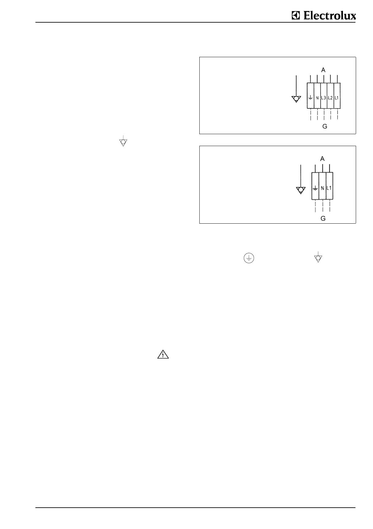
Mains connection for
electrically heated appliances
A = Mains connection
G = Appliance outputs
Fig.6 Mains connection 200-440V/3~N
Mains connection for
appliances without stirring
systems with steam or hot
water
A = Mains connection
G = Appliance outputs
Fig.7 Mains connection 200-250V/1~N


