Page is loading ...

Page 1 of 29
Assembly Instructions
Model:
MULE PRO FXR
Description:
Bluetooth Audio System
Part Number:
99994 - 0966
Assembly Time:
90 Minutes
Before you begin, read through this entire instruction packet and confirm that all parts are present
and that you have all the tools you will need.
Please note that Kawasaki cannot assume any responsibility for damage resulting from incorrect
installation.
Kawasaki recommends that all genuine accessories should be installed by an authorized
Kawasaki dealer.
The following symbols indicate the information for proper installation and operation in this instruction
NOTE: Note indicates information that may help or guide you in the separation or
service of the vehicle.
Indicates a procedural step or work to be done.
o Indicates a procedural sub-step or how to do the work of the procedural step it follows. It also
precedes the text of a NOTE.
Installation Video
When you are reading this manual electronically,
click on the picture to the right or type the web
address below to watch the “How to” installation
video.
YouTube URL
https://youtu.be/JfBsuv-fc2Y
© 2018 Kawasaki Motors Corp. USA

Page 2 of 29
Parts List
No
Component Name
Qty
Remark
1
GMR-3K Radio Assembly
1
2
Lower Speaker Pod Assembly Left
1
3
Lower Speaker Pod Assembly Right
1
4
Upper Speaker Pod Assembly Left
1
5
Upper Speaker Pod Assembly Right
1
6
Power Harness Item
1
7
Lower Speaker Harness Item
1
8
Upper Speaker Harness Item
1
9
Antenna
1
10
Accessory Input (3.5mm / USB)
1
11
Zip Ties
11
12
Push Pins
6
13
Mounting screws
4
14
Rubber Bushing Sets
8
1
2
3
4
5
7
13
9
6
8
12
11
14
10

Page 3 of 29
Tools Required
Safety Glasses
Phillips Head Screwdriver (#2) Hand Tool
T-20 Torx Hand Tool
Panel Pullers / Bojo Tool
Drill
Hole Saw 1.5 inches
Hole Saw 1 inch
Uni-Bit
2 Drill bit 3/8 inch & 3/32 inch
Marker / Pencil / Scribe
Straight Edge / Ruler
Flexible Tape Measure
Wire Cutters
Work Light
Lightweight Painter’s Tape (2 Inch & .5 Inch)

Page 4 of 29
Assembly Instructions
Park the vehicle on level ground, set the
parking brake and turn off the ignition switch.
Always wear safety glasses when working on
your vehicle.
When working on your vehicle always
remove the negative side of the battery.
Reconnecting the battery will be the last step.
You will need a flat work space.
NOTE
o Everywhere you remove a screw, push-
pin/push-rivet or harness; you should mark it
with a small piece of lightweight tape. This
assures that you replace each piece of your
vehicle and the new equipment in the proper
position.

Page 5 of 29
Assembly Instructions
Remove the dash
Remove 5 push rivets; 3 from the top of the
dash and 2 from the front of the dash.
DASH PANEL

Page 6 of 29
Assembly Instructions
Remove hand grip for the shifter and set it
aside. It will be replaced in the following steps
Using both hands, gently pull the dash
forward.

Page 7 of 29
Assembly Instructions
Before you unplug the items you should label
each for proper reconnection later.
Label and disconnect the following:
1 Dash LED panel
2 sets of accessory wires on the back of
the dash panel
4 light switches
Ignition connection (Molex)
NOTE
o For the accessory wires there are two colors
of metal tabs: copper and silver on the back
of the housing shown (1). We use this code
to label the connectors:
W (white plastic) = C (copper) tab
B (black) = S (silver) tab
You will use this code on your tape to
reconnect the wires later.
o For the dash light switches (2) we use the
code G, R, W and B to remember which
colored connector goes into which socket.
G (green) R (red) W (white) B (black)
BACK OF DASH
1
2

Page 8 of 29
Assembly Instructions
● The ignition connector has a grey button that
must be depressed in order for the connector
to be released.
o Use the Bojo tool for this. Do not use
anything sharp or metal, doing so will risk
damage to the connector or the wires.
● This completes the dash removal. Set the full
dash on a flat working surface with a soft
cloth or towel to prevent scratching your
dash.
● Replace the hand grip for the shifter in order
to prevent accidental leaning into the dark
piece of metal.
● Push the grip on without remounting the
screw.

Page 9 of 29
Assembly Instructions
Mounting Accessory Input (10)
NOTE
o Before cutting any plastic components on
your machine, we recommend you use the
lightweight painter’s tape.
Put a couple pieces of tape onto the left side
of the glove box. You will mark 2.75 inches
(40mm) down from the top and (70mm) 2.75
inches from the front edge.
● Using your 1 inch (25mm) hole saw, slowly a
hole that will allow the RCA cables and USB
cables to pass through into the glove box.
NOTE
o Do not allow the “X” you draw to be near the
bottom of the pocket, you do not want
incidental moisture to find an exit from this
point, only through the drain holes that are
already in place from the factory.
Remove the tape on the back of
the pocket.
2.75 X 1.5 inches
70mm x 40mm

Page 10 of 29
Pull the wires through the hole you drilled [10]
and through the plastic nut and rubber
washer for the USB accessory adapter
Screw the plastic nut onto the body of the
accessories making sure the rubber washer
is flush against the back of the glove box
10

Page 11 of 29
Assembly Instructions
Preparing the dash pocket
● Working on a soft flat surface, place the dash
face down and cover the back of the dash
pocket with strips of 2 inch lightweight
painter’s tape.
NOTE
o Due to the shape of the dash, you may find it
more stable to work on the unit upside down.
Using your straight edge, draw a line corner
to corner, creating an “X” in the center of your
dash pocket.
● Using your 1.5 inch hole saw, slowly drill a
1.5 inch hole that will allow the necessary
cables to pass through the rear of the dash
pocket.
NOTE
o Do not allow the “X” you draw to be near the
bottom of the pocket, you do not want
incidental moisture to find an exit from this
point, only through the drain holes that are
already in place from the factory.
Remove the tape on the back of
the pocket.

Page 12 of 29
Installation Instructions
UPSIDE DOWN
● Take the speaker/source unit harness [6] and
gently pass the +12v (red/fused) lead, the
black (negative) lead and the 4 speaker
connectors through the back of the hole you
just drilled.
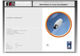
● Pull the white antenna [9] lead through this
hole at the same time.
UPSIDE DOWN
UPSIDE DOWN
9
6

Page 13 of 29
Assembly Instructions
o With the dash panel oriented upside-right,
you can see that the speaker/source unit
harness [6] and antenna [9] create a very
clean routing with plenty of accommodations
for the additional connectors on the back of
the unit.
● Connect the speaker/source unit harness [6]
and antenna [9].
1
6
9
9
6

Page 14 of 29
Assembly Instructions
Mounting the Source Unit dash panel
● Holding the source unit panel [1] in place
use the scribe to make a small mark on
the dash through the upper right screw
hole of the source unit panel [1].
● Set the source unit panel [1] aside and
prepare to drill.
Slowly drill your hole (3/32 [2mm]) where
you scribed the mark. After this first hole
is drilled, set the drill aside and hold the
source unit dash panel [1] back in place.
1

Page 15 of 29
Assembly Instructions
Using a T-20 Torx hand tool, slowly start
turning the screw [13] through the upper right
hole and into the hole you drilled. Only
tighten enough to help you steady and level
the source unit dash panel [1] again.
o With the upper right Torx screw in place, level
the panel and use the scribe to mark the
other three holes. Then, remove the Torx
screw in the upper right, set the panel aside
again and prepare to drill the other three
holes for the source unit [1] dash panel.
Once all four holes are drilled into the dash,
plug in the harness [6] and antenna [9] into
the source unit.
o With the harnesses [6] plugged in you can
now mount all four Torx [13] screws. The
dash panel [1] will be complete and ready for
re-installation after the speaker cables are
routed through the dash to the speaker
locations.
1
13

Page 16 of 29
Assembly Instructions
MOUNTING SPEAKERS & ROUTING
THE WIRES
The following steps should be performed in this
order to avoid tangling speaker wires and general
frustration.
Using the Bojo tool, remove the cup holder
on the right side of the dash.
o In order to route the speaker wire harness [8]
for the overhead pods, you will need to mount
the [2] overhead speaker pods [4 & 5] first.

Page 17 of 29
Assembly Instructions
Bring the overhead harness [8] down the right
side pillar toward the cup holder as shown.
Detach the black connectors to separate the
weather pack waterproof connectors from the
overhead wire harness [8]. This will allow the
wires to be routed into the cavity of the upper
dash behind the cup holder.
Putting your left hand into the cup holder,
feed the overhead harness end through the
body panel with your right hand and gently
pull the harness out the cup holder.
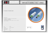
Reattach the black connectors paying close
attention to the colors and male/female
connections
Now pull the waterproof connectors and with
your left hand, toward the center of the dash.
8

Page 18 of 29
Assembly Instructions
Reconnect the black male and female
connectors making sure to match the colors.
Green – solid
Green / black line
Purple – solid
Purple / black line
Now pull the waterproof connectors with your
left hand, toward the center of the dash.
You will eventually have 4 of these
connectors coming together at this position
for overhead and under dash speakers

Page 19 of 29
Assembly Instructions
Under dash speaker wire routing
Take the loose speaker wire harness [7] with
the grey wire and feed it through the right
side of the dash.
o Using both arms, feel the wire come through
just above the wheel well. Leave the wire to
dangle.
Take the other loose speaker wire harness
[7] with the grey wire and feed it through the
right side of the dash.
o Using your arms in reverse order, you can
feel the wire come through just above the
wheel well. Leave this wire to dangle.
o Repeat this process for the left speaker wire
When complete, gather all four of the weather
pack waterproof connectors and wrap them
temporarily in the center of the dash.
UNDER DASH
7

Page 20 of 29
Assembly Instructions
NOTE
o Route all wires and harnesses behind the
shifting mechanism. Do not attach any zip
ties to this mechanism.
o All speaker wire harness color/channel is
industry standard:
Green is left / overhead speaker
o Solid green = positive (+)
o Green / black line = negative (-)
Purple is right / overhead speaker
o Solid purple = positive (+)
o Purple / black line = negative (-)
White is left / dash speaker
o Solid white = positive (+)
o White / black line = negative (-)
Grey is right / dash speaker
o Solid grey = positive (+)
o Grey / black line = negative (-)
/