Page is loading ...

Reference Manual
00809-0100-3412, Rev AA
May 2019
Rosemount
™
FCL
Free Chlorine System with Rosemount 1056 Transmitter

Essential instructions
Read this page before proceeding!
Emerson designs, manufactures, and tests its products to meet many national and international standards. Because these
instruments are sophisticated technical products, you must properly install, use, and maintain them to ensure they continue to
operate within their normal specifications. The following instructions must be adhered to and integrated into your safety program
when installing, using, and maintaining Emerson products. Failure to follow the proper instructions may cause any one of the
following situations to occur: loss of life, personal injury, property damage, damage to this instrument, and warranty invalidation.
• Read all instructions prior to installing, operating, and servicing the product.
• If this Reference Manual is not the correct one, call 1-800-999-9307 to request the correct Reference Manual. Save this
Reference Manual for future reference.
• If you do not understand any of the instructions, contact your Emerson representative for clarification.
• Follow all warnings, cautions, and instructions marked on and supplied with the product.
• Inform and educate your personnel in the proper installation, operation, and maintenance of the product.
• Install equipment as specified in the installation instructions of the appropriate Reference Manual and per applicable local and
national codes. Connect all products to the proper electrical and pressure sources.
• To ensure proper performance, use qualified personnel to install, operate, update, program, and maintain the product.
• When replacement parts are required, ensure that qualified people use replacement parts specified by Rosemount.
Unauthorized parts and procedures can affect the product's performance, place the safe operation of your process at risk, and
may result in fire, electrical hazards, or improper operation.
• Ensure that all equipment doors are closed and protective covers are in place, except when maintenance is being performed
by qualified people, to prevent electrical shock and personal injury.
WARNING
Hazardous area installation
Installations near flammable liquids or in hazardous area locations must be carefully evaluated by qualified on site safety
personnel. This device is not Intrinisically Safe or Explosion Proof.
To secure and maintain intrinsically safe installation, use an appropriate transmitter/safety barrier/sensor combination. The
installation system must be in accordance with the governing approval agency (FM, CSA, or BASEEFA/CENELEC) hazardous
are classification requirements. Consult your transmitter Reference Manual for details.
Proper installation, operation, and servicing of this sensor in a hazardous area installation are entirely the operator's
responsibility.
2

WARNING
Electrical shock
Making cable connections to and servicing this instrument require access to shock hazard level voltages, which can cause death
or serious injury.
Equipment protected throughout by double insulation.
Be sure to disconnect all hazardous voltages before opening the enclosure.
Disconnect relay contacts made to separate power sources before servicing.
Electrical installation must be in accordance with the National Electrical Code (ANSI/NFPA-70) and/or any other national or
local codes.
Unused cable conduit entries must be securely sealed by non-flammable closures to provide exposure integrity in
compliance with personal safety and environmental protection requirements. Unused conduit openings must be sealed
with NEMA 4X or IP65 conduit plugs to maintain the ingress protection rating (IP65).
Safety and performance require that this instrument be connected and properly grounded through a three-wire power
source.
Proper use and configuration is the operator's responsibility.
No external power to the instrument of more than 69 Vdc or 43 V peak is allowed, with the exception of power and relay
terminals. Any violation will impair the safety protection provided.
Do not operate this instrument without the front cover secured. Refer installation, operation, and servicing to qualified
personnel.
WARNING
This product is not intended for use in the light industrial, residential, or commercial environments per the instrument's
certification to EN50081-2.
CAUTION
Sensor/process application compatibility
The wetted sensor materials may not be compatible with process composition and operating conditions.
Application compatibility is entirely the operator's responsibility.
WARNING
Physical access
Unauthorized personnel may potentially cause significant damage to and/or misconfiguration of end users’ equipment. This
could be intentional or unintentional and needs to be protected against.
Physical security is an important part of any security program and fundamental to protecting your system. Restrict physical
access by unauthorized personnel to protect end users’ assets. This is true for all systems used within the facility.
3

4

Contents
Chapter 1 Description and specifications........................................................................................7
1.1 Specifications................................................................................................................................... 7
1.2 Ordering information....................................................................................................................... 8
Chapter 2 Install...........................................................................................................................11
2.1 Unpack and inspect........................................................................................................................ 11
2.2 General installation information..................................................................................................... 11
2.3 Sample requirements..................................................................................................................... 12
2.4 Mounting, inlet, and drain connections.......................................................................................... 12
2.5 Install the sensor(s).........................................................................................................................15
Chapter 3 Wire............................................................................................................................ 19
3.1 Wire power.....................................................................................................................................19
3.2 Wire analog outputs.......................................................................................................................19
3.3 Alarm wiring...................................................................................................................................20
3.4 Wire sensor.................................................................................................................................... 22
3.5 Quick Start..................................................................................................................................... 23
Chapter 4 Display and operation.................................................................................................. 29
4.1 Display........................................................................................................................................... 29
4.2 Keypad........................................................................................................................................... 30
4.3 Program the transmitter.................................................................................................................32
4.4 Security.......................................................................................................................................... 34
4.5 Using hold...................................................................................................................................... 35
4.6 Configure the main display.............................................................................................................36
Chapter 5 Programming the transmitter......................................................................................39
5.1 Programming overview.................................................................................................................. 39
5.2 Default settings.............................................................................................................................. 39
5.3 Configuring, ranging, and simulating outputs................................................................................ 42
5.4 Configuring alarms and assigning setpoints....................................................................................46
5.5 Configuring the measurement....................................................................................................... 53
5.6 Configuring temperature related settings...................................................................................... 56
5.7 Configuring security settings..........................................................................................................58
5.8 Set up diagnostics.......................................................................................................................... 60
5.9 Resetting the transmitter............................................................................................................... 61
Chapter 6 Calibrate...................................................................................................................... 63
6.1 Introduction................................................................................................................................... 63
6.2 Calibrate temperature.................................................................................................................... 63
6.3 Calibration - free chlorine............................................................................................................... 64
6.4 Calibration - pH.............................................................................................................................. 69
Reference Manual Contents
00809-0100-3412 May 2019
Rosemount FCL 1056 v

6.5 Calibration - analog outputs........................................................................................................... 73
Chapter 7 Digital communications............................................................................................... 75
Chapter 8 Maintenance................................................................................................................77
8.1 Replace sensor circuit board........................................................................................................... 77
8.2 Chlorine sensor...............................................................................................................................78
8.3 pH sensor....................................................................................................................................... 81
8.4 Constant head flow controller........................................................................................................ 81
Chapter 9 Troubleshoot............................................................................................................... 85
9.1 Overview........................................................................................................................................ 85
9.2 Use the diagnostic feature..............................................................................................................85
9.3 Troubleshooting when a Fault message is showing.........................................................................86
9.4 Troubleshooting when a Warning message is showing...................................................................91
9.5 Troubleshooting when no error message is showing...................................................................... 93
9.6 Troubleshooting when no error message is showing - pH............................................................... 97
9.7 Troubleshooting when no error message is showing - general......................................................101
9.8 Simulate inputs - chlorine............................................................................................................. 102
9.9 Simulate pH input.........................................................................................................................103
9.10 Simulating temperature............................................................................................................. 104
Contents Reference Manual
May 2019 00809-0100-3412
vi Emerson.com/Rosemount

1 Description and specifications
1.1 Specifications
Rosemount
™
1056 Transmitter
For Rosemount 1056 Transmitter specifications, see the Rosemount 1056 Transmitter
Reference Manual on Emerson.com/Rosemount: Manual: Rosemount 1056 Dual-Input
Transmitter.
Table 1-1: General Specifications
Characteristic Specification
Sample requirements • Pressure: 3 to 65 psig (122 to 549 kPa abs). A
check valve in the inlet prevents the sensor
flow cells from going dry if sample flow is
lost. The check valve opens at 3 psig (122
kPa abs). If the check valve is removed,
minimum pressure is 1 psig (108 kPa abs).
• Temperature: 32 to 122 °F (0 to 50 °C)
• Minimum flow: 3 gal/hr (11 L/hr)
• Maximum flow: 80 gal/hr (303 L/hr); high
flow causes the overflow tube to back up.
Sample conductivity >50 µS/cm at 77 °F (25 °C)
Process connection ¼-in. OD tubing compression fitting (can be
removed and replaced with barbed fitting for
soft tubing)
Drain connection ¾-in. barbed fitting. Sample must drain to open
atmosphere.
Wetted parts Overflow sampler and flow cell: acrylic,
polycarbonate, Kynar
®
, nylon, and silicone
Chlorine sensor: Noryl
®
, Viton
®
, wood, silicone,
polyethersulfone, polyester, and platinum
pH sensor (Rosemount
™
3900VP): Stainless
steel, glass, Teflon
®
, polyphenylene sulfide,
EPDM, and silicone
Response time to step change in chlorine
concentration
< 80 sec to 95% of final reading for inlet sample
flow of 3 gph (11 L/hr)
Weight/shipping weight (rounded up to nearest
1 lb. or 0.5 kg)
Rosemount FCL-01: 10 lb./13 lb. (4.5 kg/6.0 kg)
Rosemount FCL-02: 11 lb./14 lb. (5.0 kg/6.5 kg)
Table 1-2: Sensor Specifications
Characteristic Specification
Free chlorine range 0 to 10 ppm as Cl
2
. For higher ranges, consult
the factory.
Reference Manual Description and specifications
00809-0100-3412 May 2019
Rosemount FCL 1056 7

Table 1-2: Sensor Specifications (continued)
Characteristic Specification
pH correction range 6.0 to 9.5. For samples having pH between 9.5
and 10.0, consult the factory. If pH <6.0,
correction is not necessary. For manual pH
correction, choose option -01. For continuous
pH correction, choose option -02.
Accuracy Accuracy depends on the accuracy of the
chemical test used to calibrate the sensor.
Interferences Monochloramine, permangante, and peroxides
Electrolyte volume 25 mL (approx.)
Electrolyte life 3 months (approx.); for best results, replace
electrolyte monthly.
1.2 Ordering information
The Rosemount
™
FCL is a system used for measuring free chlorine in aqueous samples.
This complete system consists of a free chlorine sensor (pH sensor optional), a transmitter,
and a constant head overflow device to control sample flow. All components are mounted
on a backplate. The factory ships three replacement membranes and a 4 oz. (118 mL)
bottle of electrolyte solution with the system.
Free Chlorine System
Table 1-3: Free Chlorine System
Code Measurement option
01 Without pH sensor
02 With pH sensor
Code Transmitter option
220 Rosemount 1056-03-24-38-AN, 115/230 Vac 50/60 Hz, alarm relays, analog outputs,
chlorine only (option -01 only)
221 Rosemount 1056-03-24-32-AN 115/230 Vac 50/60 Hz, alarm relays, analog outputs,
chlorine and pH (option -02 only)
Typical model number: FCL-01-220
Component parts
Table 1-4: Transmitter
Transmitter model Description
1056-03-24-38-AN Rosemount 1056-03-24-38-AN, 115/230 Vac 50/60 Hz, alarm relays,
analog outputs, chlorine only
1056-03-24-32-AN Rosemount 1056-03-24-32-AN, 115/230 Vac 50/60 Hz, alarm relays,
analog outputs, chlorine and pH
Description and specifications Reference Manual
May 2019 00809-0100-3412
8 Emerson.com/Rosemount

Table 1-5: Sensor
Sensor model Description
499ACL-01-54-VP Free chlorine sensor with Variopol connector
3900VP-02-10 pH sensor with Variopol connector
Table 1-6: Cable
Sensor cable Description
23747-04 Interconnecting cable, Variopol for Rosemount 499ACL sensor, 4 ft. (1.2
m)
24281-05 Interconnecting cable, Variopol for Rosemount 3900VP sensor, 4 ft. (1.2
m)
Accessories
Table 1-7: Tag
Part number Description
9240048-00 Tag, stainless steel (specify marking)
Reference Manual Description and specifications
00809-0100-3412 May 2019
Rosemount FCL 1056 9

Description and specifications Reference Manual
May 2019 00809-0100-3412
10 Emerson.com/Rosemount

2 Install
2.1 Unpack and inspect
Procedure
1. Inspect the shipping container(s). If there is damage, contact the shipper
immediately for instructions.
2. If there is no apparent damage, unpack the container(s).
3. Ensure that all items shown on the packing list are present.
If items are missing, notify Emerson immediately.
2.1.1
Rosemount
™
FCL-01 (free chlorine without continuous
pH correction)
The Rosemount FCL-01 consists of the following items mounted on a back plate.
1. Rosemount 1056-03-24-38-AN transmitter with sensor cable attached.
2. Constant head overflow sampler with flow cell for chlorine sensor.
The free chlorine sensor (Rosemount 499ACL-01-54-VP), three membrane assemblies,
and a bottle of electrolyte solution are in a separate package.
2.1.2
Rosemount
™
FCL-02 (free chlorine with continuous pH
correction)
The Rosemount FCL-02 consists of the following items mounted on a back plate:
1. Rosemount 1056-03-24-32-AN transmitter with sensor cables attached.
2. Constant head overflow sampler with flow cells for pH and chlorine sensors.
3. Stand to hold pH buffer solution during calibration.
The free chlorine sensor (Rosemount 499ACL-01-54-VP), shipped with three membrane
assemblies and a bottle of electolyte solution, and the Rosemount 3900VP-02-10 pH
sensor are in separate packages.
2.2 General installation information
1. Although the system is suitable for outdoor use, do not install it in direct sunlight or
in areas of extreme temperature.
Reference Manual Install
00809-0100-3412 May 2019
Rosemount FCL 1056 11

CAUTION
Hazardous areas
The system is not suitable for use in hazardous areas.
2. To keep the transmitter enclosure watertight, install plugs (provided) in the unused
conduit openings.
3. Install the system in an area where vibrations and electromagnetic and radio
frequency interference are minimized or absent.
4. Be sure there is easy access to the transmitter and sensor(s).
2.3 Sample requirements
Be sure the sample meets the following requirements:
1. Temperature: 32 to 122 °F (0 to 50 °C )
2. Pressure: 3 to 65 psig (122 to 549 kPa abs)
3. Minimum flow: 3 gal/hr (11 L/hr)
2.4 Mounting, inlet, and drain connections
The Rosemount
™
FCL is intended for wall mounting only.
Refer to Figure 2-1 or Figure 2-2 for details. The sensor(s) screw into the flow cell adapters
as shown in the figures. For Rosemount FCL-02 (free chlorine with continuous pH
adjustment), you must also install the pH sensor.
Install Reference Manual
May 2019 00809-0100-3412
12 Emerson.com/Rosemount

Figure 2-1: Rosemount FCL-01
A. Chlorine sensor
B. Inlet
C. Drain
Reference Manual Install
00809-0100-3412 May 2019
Rosemount FCL 1056 13

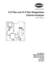
Figure 2-2: Rosemount FCL-02
A. pH sensor
B. Chlorine sensor
C. Inlet
D. Drain
A ¼-in. OD tubing compression fitting is provided for the sample inlet. If desired, you can
remove the compression fitting and replace it with a barbed fitting. The fitting screws into
a ¼-in. FNPT check valve. The check valve prevents the sensor flow cell from going dry if
sample flow is lost.
The sample drains through a ¾-in. barbed fitting.
1. Attach a piece of soft tubing to the fitting and allow the waste to drain to open
atmosphere.
Important
Do not restrict the drain line.
Install
Reference Manual
May 2019 00809-0100-3412
14 Emerson.com/Rosemount

2. Adjust the sample flow until the water level is even with the central overflow tube
and excess water is flowing down the tube.
3. Confirm that sample is flowing through the flow cells.
2.5 Install the sensor(s)
Emerson provides the Rosemount
™
FCL with the sensor cable pre-wired to the transmitter.
Procedure
1. Connect the chlorine sensor (Rosemount 499ACL-01-54-VP) to the cable labeled
CL.
2. Connect the pH sensor (Rosemount 3900-VP-02-10) to the cable labeled pH.
The terminal end of the sensor is keyed to ensure proper mating with the cable
receptacle.
3. Once the key has slid into the mating slot, tighten the connection by turning the
knurled ring clockwise.
4. Screw the sensor(s) into the plastic fitting(s), which are held in the flow cell(s) by the
union nut.
Do not remove the protective cap on the sensor(s) until ready to put the sensor(s) in
service.
Reference Manual Install
00809-0100-3412 May 2019
Rosemount FCL 1056 15

Figure 2-3: Rosemount FCL-01
A. Chlorine sensor
B. Inlet
C. Drain
Install Reference Manual
May 2019 00809-0100-3412
16 Emerson.com/Rosemount

Figure 2-4: Rosemount FCL-02
A. pH sensor
B. Chlorine sensor
C. Inlet
D. Drain
Reference Manual Install
00809-0100-3412 May 2019
Rosemount FCL 1056 17

Install Reference Manual
May 2019 00809-0100-3412
18 Emerson.com/Rosemount

3 Wire
3.1 Wire power
Wire AC mains power supply to the power supply board, which is mounted vertically on
the left hand side of the transmitter enclosure.
WARNING
Electrical shock
Electrical installation must be in accordance with the National Electrical Code (ANSI/
NFPA-70) and/or any other applicable national or local codes.
The power connector is at the top of the board.
Procedure
1. Unplug the connector from the board and wire the power cable to it.
Lead connections are marked on the connector. (L is live or hot; N is neutral; the
ground connection has the standard symbol.)
2. Run the power wiring through the conduit opening nearest the power terminal.
AC power wiring should be 14 gauge or greater.
3. Provide a switch or breaker to disconnect the transmitter from the main power
supply.
4. Install the switch or breaker near the transmitter and label it as the disconnecting
device for the transmitter.
3.2 Wire analog outputs
Two analog output currents are located on the main circuit board, which is attached to the
inside of the enclosure door.
Figure 3-1 shows the locations of the terminals. The connectors can be detached for
wiring. TB-1 is output 1. TB-2 is output 2. Polarity is marked on the circuit board.
Reference Manual Wire
00809-0100-3412 May 2019
Rosemount FCL 1056 19

Figure 3-1: Analog output connections
The analog outputs are on the main board near the hinged end of the enclosure door.
For best EMI/RFI protection, use shielded output signal cable enclosed in earth-grounded
metal conduit.
Keep output signal wiring separate from power wiring. Do not run signal and power or
relay wiring in the same conduit or close together in a cable tray.
3.3 Alarm wiring
The alarm relay terminal strip is located just below the power connector on the power
supply board.
See Figure 3-2.
Wire
Reference Manual
May 2019 00809-0100-3412
20 Emerson.com/Rosemount
/