Page is loading ...

LEK
Installation
instruction
C 460
www.contura.eu
Installation instruction 1
Installationsanleitung 20
Monteringsvejledning 40
Installasjonsanvisning 60
Asennusohje 80
GB
FI
DE
DK
NO

PRODUCT
Product type Stove lit with solid biofuels
Type designation Contura 460
Manufacturing number See rating plate on the stove
Intended area of use Heating of rooms in residential buildings
Fuel Wood
MANUFACTURER
Name NIBE AB / Contura
Address Box 134, Skulptörvägen 10
SE-285 23 Markaryd, Sweden
CHECKS
According to AVCP System 3
European standard EN 13240:2001 / A2:2004
Test institute Rein-Ruhr Feuerstätten Prüfstelle, NB 1625,
has checked declared performance and issued test report no. RRF-40 05 932
PERFORMANCE DECLARATION
No. C460-CPR-130605-SE-1
DECLARED PERFORMANCE
Essential characteristics Performance Harmonised technical
specification
Reaction to fire A1 WT
Minimum distance to combustible material 50 mm to rear
330 mm to side
Other safety distances according to
the installation instructions
Risk of falling embers Approved
Emissions from combustion CO 0.12%
NOx 25 mg/m
3
OGC 84 mg/m
3
PM 67 mg/m
3
Surface temperatures Approved
Cleaning options Approved
Mechanical durability Approved
Emissions of hazardous substances Approved
Nominal output 7 kW
Efficiency 80%
Flue gas temperature in connector at nominal
output
255°C
EN 13240:2001 / A2:2004
The undersigned is responsible for the manufacture and conformity with the declared performance.
Niklas Gunnarsson,
Business area manager NIBE STOVES
Markaryd, 1st July 2013

Contents
Technical specifications 2
Installation distances to walls and ceiling 3
Air supply 4
Unpacking 5
Fitting the fire-box surrond 6
Fitting the smoke baffle 6
Positioning the base-plate 7
Making a hole through the ceiling 7
Installing the C-460 wall-protection panel 7
Fitting the rear panel 8
Positioning the fire-box 9
Installing the heat-retaining blocks 9
Top flue connection to steel chimney 9
Rear flue connection to masonry chimney 10
Assembling the concrete surround 11–17
How to use the stove 18
A warm welcome to Contura
A warm welcome to the Contura family. We hope you will
get a great deal of pleasure from your new stove. As a
new owner of a Contura stove, you have secured a pro-
duct with timeless design and long service life. Contura
also has a combustion process that is both environmen-
tally friendly and efficient, for the best heat production.
Read through these installation instructions carefully befo-
re installation. Read how to best light your stove in the
lighting instructions.
WARNING!
The stove becomes very hot
During operation, certain surfaces of the stove become
very hot and can cause burn injury if touched. Also,
take heed of the strong heat radiated through the door
glass. Placing flammable material closer than the safe
distance indicated may cause a fire. Smoulder combustion
can cause quick gas ignition with the risk of damage to
property and personal injury.
NOTE!
Report the installation of a stove to your
local authority.
The owner of the house is personally responsible
for ensuring compliance with the mandatory safety
requirements and must have the installation approved
by a qualified inspector. Your local chimney sweep
must also be informed about the installation as this
will affect the routines for regular chimney-sweeping
services.

GB
2
LEK
R khylla
Rostertallrik
Gjutgodsbotten
T ckbitar
Brasbegr nsare
Askl da
Eldstadsbekl dnad
Pl tprofiler
Technical specifications
Output 3–9 kW
Efficiency, up to 80 %
Weight, tall model 370 kg
Weight, low model 340 kg
Weight: height extension piece 400 mm 20 kg
Weight: height extension piece 100 mm 5 kg
Weight: marble floor slab. 26 kg
Stove width 890 mm
Depth 700 mm
Height, tall model 2380 mm
Height, low model 1590 mm
Connecting sleeve (internal dia.) Ø150 mm
Type approved in accordance with:
European standard EN-13240 class 1
Swedish environmental and quality certification,
“P marked” cert. no. 22 03 07
Swedish type approval, cert. no. 0887/99
Norwegian standard NS 3059, certificate no. 043-088
German standard DIN 18.891, RO-91 00 138
Danish standard 887-1, id nr 598
General information
This folder contains instructions on how to assemble and
install stoves in the Contura 460. The stove also comes with
comprehensive Lighting and Maintenance Instructions. Please take
time to read all this information carefully and keep it in a safe place
for future reference.
Contura 460 stoves have been type-approved in Sweden for
connection to a chimney which can withstand flue gas temperatures
of 350°C. The connecting sleeve has an external diameter of 150
mm.
To ensure proper combustion, sufficient air must be supplied to the
stove from outdoors.
Building permission
It may be necessary for you to apply for building permission from
your local planning authority before installing a stove or erecting
a chimney. Before start ing installation work, make sure that you
check which regulations apply.
Structural support
Check to make sure that the floor is strong enough to support the
weight of the stove and chimney. If you intend to locate the stove
on standard wooden floor joists, contact a professional builder to
make sure that the construction will withstand the load. If the total
weight of the stove and the chimney together does not exceed 400
kg it is not normally necessary to reinforce the wooden floor joists.
Floor plate
To protect the floor from sparks and falling embers the stove must
stand on a non-combustible surface which extends at least 300
mm in front of the stove and 100 mm along each side. As other
statutory requirements apply in some countries, we recommend
that you consult the relevant authority or an authorised chimney-
sweep in your area.
Chimney
The draught in the chimney must generate a neg ative pressure
of at least 12 Pa. The draught is affected both by the length and
cross-sectional area of the chimney, and by how well sealed the
construction is. The shortest recommended chimney length is
3.5 metres. The cross-sectional area of the chimney must be
approximately 150–200 cm² (140–160 mm in diameter).
Make sure that there are no gaps around soot hatch es and flue-
pipe connections.
Remember that the draught is reduced in flues with sharp bends or
horizontal sections. A horizontal flue length of up to 1.0 metre is
permissible, provided that the vertical flue is at least 5.0 metres in
height.
It must be possible to clean the flue throughout its entire length,
and the soot hatches must be easily accessible.
Fire-box surround
Grate disc
Cast-iron fire-bed
Cover strips
Smoke baffle
Fire-bars
Ash-pan
Sheet metal profiles

GB
3
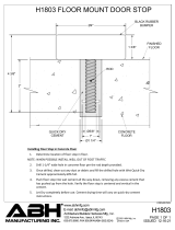
Lay the metal template as a base-plate (see page 8) where the
stove is to stand and measure to make sure that the stove is
no closer to the wall than the minimum distances specified in
the diagrams below. A hole in the template marks the centre
of the chimney. The rear edge of the template must be flush in
line with the rear edge of the concrete surround. Allow at least
1.0 metre from the stove door to any combustible part of the
building structure or interior fittings.
330
250
50
775
240
Floor plate (accessory)
Centre mark for
chimney
Combustible wall
445
890
520
740
Air inlet Ø64
1025
700
305
410
450
1590
370
930
626
Air inlet Ø64
445
890
Ø280
OBS! Min. 20 mm
Min. 2200 mm
1135
1575
470
Air inlet Ø64
1020
700
305
385
190
450
2380
370
930
2715
1135
2655
Air inlet Ø64
Installation distances to walls and ceiling
1040
190
925
Floor plate (accessory)
Centre mark for
chimney
1200 (min 900)
330
250
775
50
240
Combustible wall
Wall-protection panel
C-460 (accessory)
Floor plate (accessory)
330
250
775
190
Floor plate (accessory)
Centre mark for
chimney
Combustible wall
Fire-retardant wall of
brick or concrete
Centre mark for
chimney
Against combustible wall
Against combustible wall with
protective screen
Against non-combustible wall

GB
4
Air supply
Combustion air for the stove can be supplied through a duct
directly from outside, or indirectly through a vent in the wall of
the room where the stove is installed. Flexible tubing is available
as an accessory.
The drawings below show various alternative meth ods of
supplying the stove with air.
The air duct connection on the stove has an external diameter of
64 mm.
Important!
To prevent condensation in air ducts which pass through heated
areas, the duct must be insulated with 30 mm of mineral wool
covered with aluminium tape.
It is important to seal carefully around the duct where it passes
through the wall or floor. Use joint ing compound. For ducts longer
than 1.0 metre, the diameter must be increased to 100 mm, and
the size of the air vent increased correspondingly.
Through the external wall.Indirect air supply through the external wall.
LEK
Through the floor and foundation slab.Through a suspended floor/wall-and-cavity
foundation.
LEK
LEK
LEK
30 mm

GB
5
87
2
3
1
LEK
87
2
3
1
LEK
Unpacking
Remove the cast-iron cover strips below the side windows.
LEK
LEK
LEK
Remove the grate disc by lifting the edge furthest away from
the draught control bar.
Lift the cast-iron fire-bed at one side and tilt it so that it can be
removed through the door opening.
87
2
3
1
LEK
First remove all the components from the fire-box and place the
steel profiles and metal plates on one side.
Unsecure the stove on the delivery pallet and fit the extension legs
using the hexagon screw s. By fitting these legs before removing
the stove from the pallet you can avoid scratches to the floor. Raise
the fire-box to a height of 87 mm and tighten the lock-nut.
LEK
Unscrew the metal brackets from the rear edge of the side
windows.
LEK
LEK
Lift and transport the stove as
shown in the sketch!
The cast-iron door and fire-bed may be re moved to make the stove
lighter and easier to move.

GB
6
Fitting the fi re-box surrond
LEK
LEK
LEK
Vermiculitehållare
LEK
Remove the cast-iron cover strips below the side windows. Unscrew the metal brackets from the rear edge of the side
windows.
Slot the two front fire-bricks. Screw the retaining brackets back
into place and replace the cover strips.
Fit the rear fire-brick.
LEK
LEK
Lift the door upwards until it disengages from the lower hinge. Ease the bottom of the door slightly sideways until it clears the
hinge pin. Lower the door to disengage it completely.
Fitting the smoke ba± e
Raise the folded front edge of the smoke baffle
up over the side pegs. Then lift the rear edge of
the baffle up over the vermiculite holder.
LEK
Stödtapp, sida Vermiculitehållare
LEK
Side peg
Vermiculite
holder
Vermiculite holder
!
When correctly placed on top of the
supporting pegs, the baffle slopes
upwards from the back to the front.

GB
7
44
380
c:a 50
380
Making a hole through the ceiling
When drawing a flue from the top of the stove to a steel
chimney, you need to make a hole through the ceiling. Ensure
that the centre of the hole is directly above the mark on the
base-plate (the floor template) that indicates the centre of
the chimney. For chimney installation, please refer to the
installation instructions supplied with the chimney.
At this stage fit only the rear section of the ceiling insulation. It
is important that the ceiling insulation plate is centred over the
hole in the ceiling.
Installing the C-460 wall protection panel
Screw the outer steel profiles to the wall 1200 mm apart.
Ensure that they are absolutely perpendicular. Place the air
holes by the floor and ceiling. The two profiles are 2500 mm
long. If the ceiling is lower, use a hacksaw or metal shears to cut
the profiles to the appropriate height. To make this easier, there
is a die-cut slot 100 mm from the end (see illustration). Place
the two remaining profiles between the outer ones.
Cut the minerit boards to the desired width. Position the minerit
boards edge to edge with a bead of acrylic sealant in the gap
and screw them into place with the supplied screws. Do not
install the upper board until the rear section of the headlining
seal has been installed.
LEK
Utstansning
LEK
Utstansning
Positioning the base-plate
The metal template indicates the position of the stove body, the
concrete surround and the hole in the ceiling for the flue. The
rear edge of the surround will later be aligned exactly with the
rear edge of the template.
Place the base-plate on the floor – after first ensuring that
you have observed all the requisite safety distances (see page
3) – so that the hole in the plate that marks the centre of the
chimney is at the required distance from the wall. If a wall
protection panel is to be installed, the template is fitted against
the panel.
Screw the base-plate to the floor.
LEK
Die-cut slot

GB
8
Fitting the rear panel
Secure the vent screen to the rear panel.
LEK
Vent screen
Rear panel
Screw the rear panel to the supporting profiles
of the stove body.

GB
9
LEK
Installing the heat-retaining blocks
Place the seven olivine blocks on the ledge as shown.
Positioning the fire-box
Position the fire-box on the template so that the front legs are
centred over the markings.
LEK
Fit the fan (optional accessory) in accordance with the
Installation Instructions for Fan 2000/C460.
Follow the instructions on page 7 when making a hole through
the ceiling. Slide the flue base over the collar. Make sure that
the seal round the collar is not dislodged. If further sealing
material is required, heat-resistant sealant may be used.
LEK
Top flue connection to steel chimney

GB
10
Mark out the centre of the hole to be made in the wall for a rear
flue connection. Make a hole at least 180 mm in diameter and then
secure the flue sleeve in the wall using heat-proof mortar (not
supplied).
Check the height to make sure that the hole aligns with the
chimney connection on the rear of the stove. Leave the mortar to
dry before connecting the stove to the flue.
LEK
LEK
Seal the joint between the sleeve and the connecting flue with
sealing rope.
Slide the connecting flue over the collar. Make sure that the seal
round the collar is not dislodged. If further sealing material is
required, heat-resistant sealant may be used.
LEK
LEK
Täcklock
LEK
Brytlock
For rear flues, cut away the punched metal covers on
the rear panel and the heat reflector.
The stove has been prepared for top-flue connection before
delivery. For rear flue connections the collar and cover need to
exchange places.
Rear flue connection to masonry chimney
Punched
cover
Covering
cap
In the bag with these installation
instructions are two wing screws
for the cover.

GB
11
Assembling the concrete surround
Before starting the assembly work, check to make sure that none of the concrete
components have any hairline cracks that run all the way through. When assembling
the surround, use the cement supplied to bond the sections together. Mix 1 part
water with 2 parts cement. It is important that the various components are
assembled so that the finished construction is straight and true, both horizontally
and vertically. Placing the cement in little heaps rather than spreading it out as a
bed of cement makes it easier to ensure that the construction is horizontal. For the
best adhesion, it is advisable to wet surfaces that are to be joined. The cement bed
should be 1–2 mm thick when the sections have been assembled and any surplus
cement has been pressed out.
LEK
Kåpa övre
Kåpa nedre
Hylla
Sidstolpe
Sockel Passbit
sockel
Kåpa mitt
Täckplatta
Övre
marmorhylla
Nedre
marmorhylla
Passbit
asklåda
The supplied silicone is used to secure the marble
shelves and to attach the concrete sections to the
rear wall. When sealing the joint to the rear wall, only
the paint-over acrylic sealant must be used.
The silicone can also be used to repair any slight
unevenness in the concrete blocks and any minor
damage.
When the fire is lit, the metal in the fire-box
expands, so it is absolutely essential that the
concrete surround does not come into contact with
the stove body. Check that there is a gap of at least
2-3 mm between the stove body and the surround.
Hood base
Mantelshelf
Side column
Plinth
Filler-piece for plinth
Filler-piece
for ash-pan
Bottom
marble shelf
Top marble shelf
Hood top
Hood centre
Niche cover

GB
12
File off any uneven edges on the inside of the door. Screw the
mounting plate for the hinge into place in the pre-drilled holes
in the door, and then fit the hinge to the mounting plate.
LEK
LEK
Place the hatch in the gap in the plinth and make drilling marks.
LEK
Place the plinth on the base-plate. The rear edge of the plinth
must be flush with the rear edge of the base-plate.
Simply stand the filler-piece for the plint h loose in place, or
squeeze out a few small blobs of acrylic sealant to keep it from
moving. Note, however, that it must be possible to remove the
filler-piece when cleaning the stove or servicing the fan.
If a fan is to be connected, make holes for the
cables either in the wall or in the back of the plinth.
Draw the cables through the hole before securing
the plinth to the base-plate.
LEK
LEK
Drill as marked with a 5 mm drill. Press screw plugs into the
holes and screw the hinges into place.
Adjust the hatch to an exact fit by turning the adjust ing screws
on the hinges. Turn the screw as indicated by the arrows
stamped into the metal.
LEK
!

GB
13
Cement the side columns in place left and right on the
marble shelf.
LEK
Use the full-threaded bolts to anchor the shelf to the plinth.
Before tightening the nut, make sure that the bolts are pushed
fully into the grooves and that the rectangular washers cover
the groove entirely.
LEK
LEK
The gap between the rebate in the concrete components and
the rear panel must be carefully sealed with silicone. This is
necessary to prevent the wrong kind of convection currents in
the warm air. Squeeze out a liberal amount of silicone all along
the edge of the rear panel. Any surplus pressed out when the
con crete sections are fitted can be smoothed by hand if you
first dip your finger in soapy water.
Cement the mantelshelf in place on top of the side columns.
!

GB
14
LEK
Dab a few heaps of cement
on the mantelshelf and lift
the hood base into place.
Screw the heat reflector into place on the sealing plate. Lay the
sealing plate in place inside the hood base and fix it to the rear
panel with screws.
If the stove is to be connected to a top flue, cut away the punched
cover. Insulate the sealing plate with the blocks of insulating
material supplied. For the low model, only one of the insulation
blocks is required.
LEK
LEK
In this instance it is extra important
to make sure that there is a tight
seal between the concrete surro und
and the rear panel as hot air will be
collecte d in this cavity.
If you are installing the low 460 model, you can now fit the marble
top to the hood base using silicone.
LEK
Sealing plate
Heat reflector
Use silicone to attach the
cover to the rear wall.
! !

GB
15
Screw the front section of the ceiling insulation into place leaving a gap of 4–5 mm to the flue casing. Make sure that the ceiling insulation is
held in place firmly against the ceiling. Hold the rubber sealing strip so that the gills are facing the flue casing and press the strip into place
in the gap around the chimney. Seal and use insulating blocks to insulate in the roof/floor above the ceiling insulation.
LEK
Lay the first insulating block on top of the sealing plate. Make
sure that the insulation forms a tight seal around the flue base
(the start section of the flue) and the concrete surround. Then fit
the second insulating block in place. This has a larger hole in the
middle and should form a tight seal with the outside of the chimney
module. Fit the bottom chimney module into place.
Startrör
Avtätningsplåt
Isoleringsskiva
Isoleringsskiva
Stoppbricka
Övergångsisolering
Skorstensmodul
LEK
Spalt 4-5 mm
LEK
Gap 4-5 mm
Chimney module
Insulation
Retaining plate
Insulating panel
Insulating panel
Flue base
Sealing plate

GB
16
LEK
LEK
Cement the remaining concrete sections into place together with any height-extension pieces that may be necessary. Leave a gap of at least
20 mm between the top of the chimney surround and the ceiling.
LEK
Fill the two expansion
gaps in the hood
with acrylic sealant.
LEK
Fix the marble slabs to the mantelshelf with silicone.
!

GB
17
Fill the gaps between the concrete surround and the wall-
protection panels, and those between the metal profiles of the
wall-protection panels with acrylic sealant. Before starting this
work, clean the profiles with mineral spirits or a similar kind of
solvent.
When the cement and the acrylic sealant have dried, paint the
entire concrete surround and the wall-protection panels with a
textured coating. Allow the paint to dry for 24 hours and then
go over the painted areas with a latex paint (gloss 07). Take
precautions to protect the stove body against paint splashes.
Wait for the cement to dry for at
least one week before lighting a
fire in the stove.
LEK
Use the adhesive to fill the gaps between the different sections of
the chimney hood, adding pieces of fibre-glass tape to reinforce
the seal. The adhesive should also be used to fill the gap between
the hood and the marble slabs of the shelf. The gap between
the concrete surround and the marble shelf is filled with acrylic
sealant.
LEK
The grilles are simply placed loose over the air vents. Before fitting
the metal floor-plate (optional accessory) around the stove plinth,
cut away the inside section and smooth off any jagged edges or
burrs. The marble floor slab (optional accessory) may simply be laid
loose around the plinth or cemented in place on the floor below
If you prefer, you can fit the special niche cover to conceal the
niche. Fit the cover flush with the outer contours of the hood and
secure it with adhesive. Seal the gap around the cover with acrylic
sealant
!

GB
18
LEK
ÖPPET
ÖPPET
Roster
Förbränningsluft
OPEN
Air supply
Grate
OPEN
How to use the stove
Under normal conditions we recommend that the stove burns 2
kg of wood per hour. The maximum permissible amount is 3.5 kg
per hour. Most types of wood can be used: deciduous (broad-leaf)
woods are preferable, as they generally burn more calmly. It is
important that the wood is dry and that logs are of a suitable size:
about 25–35 cm long and 7–9 cm in diameter. Always open and
close the door slowly and carefully to prevent the sudden changes
in pressure inside the stove which otherwise can cause a back-
draught of smoke in the room.
1. Open the air supply control by moving the damper
spindle to the right.
2. Place newspaper or a firelighter in the fire-box. Then
stack about 3–3.5 kg of fine-split logs on the fire-bed,
laid in a criss-cross pattern as shown.
3. Light the fire.
4. Push the door to, but do not close it until the fire is
burning well (after about 10–15 minutes).
5. When the first pile of logs has burnt down, stoke up the
fire again by placing 3 or 4 logs (weighing 2–2.5 kg in all)
on the embers.
Pulling out the damper bar opens the grate disc. This should only
be done for a short time when lighting or re-stoking the fire to
ensure that the wood catches light quickly, and when riddling the
ash into the ash pan. If the grate is left open for a long time, the
stove and the chimney may be damaged as a result of the excessive
heat.
Important!
It is essential that the wood starts to burn quickly. Smouldering
produces excessive amounts of smoke and may, in exceptional
circumstances, cause the fumes produced to ignite spontaneously
and damage the stove. You can get the logs to burn quickly by
opening the grate disc for a short while after re-stoking the fire,
or by leaving the door ajar until the wood is burning.
Please read the separate Lighting and
Maintenance Instructions carefully before
lighting the stove for the first time.
!
/