Altronix EBRIDGE1CRT Installation guide
- Category
- Security cameras
- Type
- Installation guide
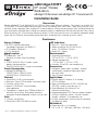
Altronix EBRIDGE1CRT enables fast Ethernet digital communication over existing legacy Coax, eliminating new network cabling costs. It facilitates system upgrades from analog to IP cameras, transmitting composite video signals simultaneously with Ethernet data. Ideal for retrofitting digital IP cameras in analog CCTV installations, extending network link distances, and upgrading deployed CCTV Coax to a digital network in various settings.
Altronix EBRIDGE1CRT enables fast Ethernet digital communication over existing legacy Coax, eliminating new network cabling costs. It facilitates system upgrades from analog to IP cameras, transmitting composite video signals simultaneously with Ethernet data. Ideal for retrofitting digital IP cameras in analog CCTV installations, extending network link distances, and upgrading deployed CCTV Coax to a digital network in various settings.


-
 1
1
-
 2
2
-
 3
3
-
 4
4


Altronix EBRIDGE1CRT Installation guide
- Category
- Security cameras
- Type
- Installation guide
Altronix EBRIDGE1CRT enables fast Ethernet digital communication over existing legacy Coax, eliminating new network cabling costs. It facilitates system upgrades from analog to IP cameras, transmitting composite video signals simultaneously with Ethernet data. Ideal for retrofitting digital IP cameras in analog CCTV installations, extending network link distances, and upgrading deployed CCTV Coax to a digital network in various settings.
Ask a question and I''ll find the answer in the document
Finding information in a document is now easier with AI
Related papers
-
Altronix EBRIDGE1CRT Installation guide
-
Altronix EBRIDGE1CR Installation guide
-
-
Altronix EBRIDGE16CR Installation guide
-
-
-
-
-
-
Altronix eBridge1PCRM Installation guide
Other documents
-
Sony EBRIDGE1CR Datasheet
-
eBridge CR 4 Port IP Over Coax Receiver Installation guide
-
eBridgePLUS eBridge1PCRMT Installation guide
-
Vigitron Vi30202U User manual
-
-
EverFocus EHH5205 Datasheet
-
-
Northern EOCCPK User manual
-
 UStec TP-IPR8 Owner's manual
