Runco Projector Vivix Pixel for Pixel User manual
- Category
- Plasma TVs
- Type
- User manual
This manual is also suitable for

OWNER’S OPERATING MANUAL
PFP-7/PFP-11
PIXEL FOR PIXEL
TM
TM

OWNER’S OPERATING MANUAL
PIXEL FOR PIXEL
TM
TM
PFP-7/PFP-11

The software installed in the PFP-7/PFP-11 is protected by copyright laws and International
copyright treaties, as well as other intellectual property laws and treaties.
IMPORTANT - READ CAREFULLY: This Runco License Agreement is a legal agreement between you
(either an individual or a single entity) and Runco International for the Runco software product installed
within the PFP-7/PFP-11. By using the PFP-7/PFP-11, you agree to be bound by the terms of this
License Agreement. If you do not agree to the terms of this License Agreement, do not use the
PFP-7/PFP-11; you may, however, return it to your place of purchase.
© 2001, Runco International. All rights reserved.
2

CONTENTS
3
Warnings and Safety Precautions. . . . . . . . . . . 4
Introduction . . . . . . . . . . . . . . . . . . . . . . . . . . . . 6
General Description . . . . . . . . . . . . . . . . . . . . . 6
Features and Benefits . . . . . . . . . . . . . . . . . . . 6
Front and Rear Panel Description. . . . . . . . . . . 7
Front Panel . . . . . . . . . . . . . . . . . . . . . . . . . . . 7
Rear Panel . . . . . . . . . . . . . . . . . . . . . . . . . . . 8
Remote Control Description . . . . . . . . . . . . . . 10
Quick Set-up Guide . . . . . . . . . . . . . . . . . . . . . 11
Connection Examples . . . . . . . . . . . . . . . . . . 11
Getting Started . . . . . . . . . . . . . . . . . . . . . . . 12
Overall Function Description . . . . . . . . . . . . . 13
Compatibility . . . . . . . . . . . . . . . . . . . . . . . . . 13
Menu Description and Navigation . . . . . . . . . . 14
Main Menu . . . . . . . . . . . . . . . . . . . . . . . . . . 14
Picture Quality Adjustments . . . . . . . . . . . . . . 15
Installation Menu . . . . . . . . . . . . . . . . . . . . . . 17
Screen Type . . . . . . . . . . . . . . . . . . . . . . . . . 18
Scan Rate/Resolution . . . . . . . . . . . . . . . . . . 18
Selecting a Resolution (Scan Rate) . . . . . . . . 19
Fixed Pixel Displays. . . . . . . . . . . . . . . . . . . . 20
Output Format (Sync) . . . . . . . . . . . . . . . . . . 21
Side Bar Level . . . . . . . . . . . . . . . . . . . . . . . . 22
Image Shift . . . . . . . . . . . . . . . . . . . . . . . . . . 23
Blanking . . . . . . . . . . . . . . . . . . . . . . . . . . . . 24
System Reset . . . . . . . . . . . . . . . . . . . . . . . . 24
Aspect Ratios. . . . . . . . . . . . . . . . . . . . . . . . . . 25
Dimensions . . . . . . . . . . . . . . . . . . . . . . . . . . . 27
RS-232 Communications . . . . . . . . . . . . . . . . . 28
RS-232 Commands . . . . . . . . . . . . . . . . . . . . . 29
Specifications . . . . . . . . . . . . . . . . . . . . . . . . . 31
Supplied Accessories. . . . . . . . . . . . . . . . . . . 31

4
CAUTION:
To turn off main power, be sure to remove the plug from power outlet. The power outlet socket should
be installed as near to the equipment as possible, and should be easily accessible.
REMARQUE:
Pour mettre l’appareil hors circut, s’assurer de retirer la fiche de la prise d’alimentation. La prise d’ali-
mentation doit être installé aussi proche que possible de l’appareil et doit être facile d’ accès.
TO PREVENT FIRE OR SHOCK HAZARDS, DO NOT EXPOSE THIS UNIT TO RAIN OR MOISTURE.
ALSO DO NOT USE THIS UNIT’S POLARIZED PLUG WITH AN EXTENSION CORD RECEPTACLE OR
OTHER OUTLETS, UNLESS THE PRONGS CAN BE FULLY INSERTED. REFRAIN FROM OPENING
THE CABINET AS THERE ARE HIGH-VOLTAGE COMPONENTS INSIDE. REFER SERVICING TO
QUALIFIED SERVICE PERSONNEL.
POUR EVITER UN FEU OU UN RISQUE D’ELECTROCUTION NE PAS EXPOSER CET ENSEMBLE
A LA PLUIE OU A L’HUMIDITE; DE MEME, NE PAS BRANCHER LA PRISE POLAIRE AVEC UNE
RALLONGE A MOINS QUE LES DENTS DE LA PREMIERE NE S’Y INSERENT PLEINEMENT.
EVITER D’OUVRIR LE COFFRET CAR IL Y A, A L’INTERIEUR, DES COMPOSANTS SOUMIS A UNE
HAUTE-TENSION; POUR LES REPARATIONS, S’ADRESSER A UN PERSONNEL QUALIFIE.
WARNING
AVERTISSEMENT
Warnings and Safety Precautions

5
This equipment has been tested and found to comply with the limits for a Class B digital device, pur-
suant to Part 15 of the FCC Rules. These limits are designed to provide reasonable protection against
harmful interference when the equipment is operated in a commercial environment. This equipment
generates, uses, and can radiate radio frequency energy and, if not installed and used in accordance
with the installation manual, may cause
harmful interference to radio communications. Operation of this equipment in a residential area is likely
to cause harmful interference, in which case, the user will be required to correct the interference at his
own expense.
DOC compliance Notice
This Class B digital apparatus meets all requirements of the Canadian Interference-Causing Equipment
Regulations.
DOC avis de conformation
Cet appareil numérique de la classe B respecte toutes les exigences du Réglement sur le Matériel
D’interférence du Canada.
WARNING
:
Please read and follow the safety precautions listed below to ensure the equipment is free from damage,
and to ensure that no injury will occur as a result of improper use.
• Do not insert any object, especially metal or liquids, into the PFP-7/PFP-11.
• Do not place any objects containing water or any other liquid on top of the PFP-7/PFP-11.
• Do not place the unit in direct sunlight, near heaters or in extremely dusty or humid locations
• Do not install this unit outdoors or otherwise exposed to the elements
• Do not place heavy objects on top of the unit
• If the power cord is damaged or frayed in any way, electrical shock and/or fire may result. Please do
not place objects on the power cord, and keep the cord away from heat-emitting devices. Should the
power cord become damaged in any way, please contact your Runco dealer for a replacement cord.
• Do not remove the cover of the unit for any reason. If any problems arise with the unit, please contact
a Runco dealer or Runco International for service. Removing the cover will void the warranty.
Safety Tips

Congratulations on your purchase of the PFP-7/PFP-11 video processor with Vivix™ technology! This
processor is designed to maximize the image quality of your fixed-pixel display or rear-screen television while
adding an extra level of flexibility to your system. The PFP-7/PFP-11's Vivix™ processing techniques enable
this processor to be used with virtually any fixed-pixel display from Plasmas, LCD projectors, DLP projectors
and even D-ILA projectors, and will provide the most stunning image that your display can possibly deliver.
Vivix™ is a proprietary technique developed by Runco engineers to match the output resolution of the
processor precisely to the display it will be used with. This precision processing technique resolves all the
problems that conventional video processors have with fixed-pixel displays, which include pixel-tracking
artifacts (jagged lines, moiré, jerky motion, etc.), too much overscan (significant loss of image) and even
improper and disproportionate aspect ratios. The results of Vivix™ technology is an image that nearly rivals
that of a CRT, while providing three geometrically-correct aspect ratios on a 16:9 or a 4:3 screen.
In addition to fixed-pixel displays, the 480p, 540p, 600p and 720p output options of the PFP-7/PFP-11 is
designed specifically for rear-screen high-definition capable televisions. These RPTV's are quite flexible by
themselves, but often have lower-quality processors built in leaving the NTSC image much to be desired.
The PFP-7/PFP-11 will provide the best possible image from your RPTV, while providing all the other bene-
fits that the Vivix™ technology provides including aspect ratio control. Finally, the PFP-7/PFP-11 can be
configured for either an RGB or a Component output, making this processor compatible with virtually every
HD-capable RPTV on the market today.
The PFP-7/PFP-11 have many great features and benefits that make it a flexible, high-quality processor.
Its many benefits include:
• Vivix
TM
Technology, which maximizes image quality and flexibility of fixed-pixel displays.
• An adaptive 2-dimensional comb filter that greatly reduces artifacts when using a composite
video signal as an input.
• A Luma edge enhancement circuit makes the edges of objects appear sharper without the ringing
and noise increase associated with traditional sharpness circuits
• A Chroma edge enhancement circuit is included to compensate for lower chroma resolution found
in composite and S-video.
• Inverse Telecine (3:2 pulldown) detection and processing allows the scaler to almost completely
eliminate interlace artifacts associated with other scalers
• The controller can correctly scale anamorphic, letterbox and 4:3 formats to fit on a wide aspect-ratio
screen, and scale anamorphic formats on a 4:3 screen
• A pass-through connector is supplied for routing HDTV or computer graphics directly to the display.
• An RS-232 input is provided for easy integration into the automated home theater environment
• A TBC (Time Base Corrector) circuit is provided for unstable sources such as VCR’s.
• 12V outputs are provided for drop screens and screen masking.
• A simple 7-button remote controls all aspects of operation. One button source selection and aspect ratio
control is also provided via the remote control.
6
INTRODUCTION
General Description
Features and Benefits

7
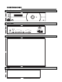
FRONT AND REAR PANEL DESCRIPTIONS
Front Panel
m
e
n
u
ratio
ratio
i
n
p
u
t
e
n
t
e
r
>
<
<
<
PIXEL FOR PIXEL
TM
1 2
3 4 5 6 7 8 9
1. IR RECEIVER
Receives the IR commands from the remote control.
2. POWER BUTTON
Toggles the power on and off. For a discreet on or off command, you can use the direct access buttons on the
remote control. NOTE: When the main AC power switch is first turned ON, the processor will go through an
initiation cycle for approximately 15 seconds. The processor cannot be turned on or operated until the
initialization is complete
3. LED DISPLAY
Indicates the model number, current source, scan rate or resolution and aspect ratio.
4. UP BUTTON
When no menus are present on-screen, the UP button will toggle you through aspect ratios in the following order:
Standard (4:3) Letterbox Anamorphic
When the menu is on-screen, the UP button will move the cursor up within the menu.
When an adjustment item has been selected (i.e. brightness), the UP button will increase the value of that
function.
5. LEFT BUTTON
When no menu is present on-screen, the LEFT button will toggle you through the four different sources, in the
order of:
Pass-through Component S-Video Composite
6. ENTER BUTTON
When an item is highlighted on the On-Screen Display, the ENTER button will select the item.
7. DOWN BUTTON
When no menu is present on-screen, this button will toggle you through the different aspect ratios.
When the menu is on-screen, the down button will move the cursor down within a menu. When an adjustment
function has been selected (i.e. brightness), the DOWN button will decrease the value of that function.
8. RIGHT BUTTON
When no menus are present on-screen, the RIGHT button will toggle you through the four different sources, in
the order of:
Composite S-Video Component Pass-through
9. MENU BUTTON
Pressing the MENU button will bring up the main menu. If no action is taken within approximately 10 seconds,
the menu will time-out (disappear). Also, if you are in an adjustment mode or function, pressing MENU will bring
the menu back one level.

8
1. 12v Fuse
This fuse protects the 12v outputs from the MASK and SCREEN jacks.
(Screen Fuse: 5mm x 25mm, AGC, 0.5A 250V Fast Acting, 250V, Fast Blow)
2. Mask
This is a 12V output that is used to trigger masking on screens that have that capability.
(For use on motorized screens only).
3. Screen
This is a 12V output that is used to trigger the screen to drop.
(For use on motorized screens only).
4. RS-232 In
This is for systems using serial (RS-232) to control the PFP-7/PFP-11.
5. Reserved for future use.
6. RGB OUTPUT
This is the main output of the PFP-7/PFP-11. The RGB Signal goes directly to the display; If
component is used through the pass-through, then only the R (Pr), G(Y) and B(Pb) jacks will be active.
Individually, the jacks are: V=vertical sync, H=horizontal sync, B=Blue, G=Green, R=Red.
Note: If setting the output for ‘sync on green’ or ‘component’ (see Installation Menu section); disconnect the
sync cables (H & V) from the processor. If using composite sync, the sync output will be on the ‘H’
connector.
7. Pass-through
Anything input to this port will by-pass the processing of the PFP-7/PFP-11 and be sent straight to the display.
This is useful for computer graphics and HDTV signals which do not require processing.
8. Component Input
This is the input for component video from sources such as DVD players.
Note: The component output from a DTV decoder or a progressive-scan DVD cannot be used with this port;
it must be input to the Pass-through port.
9. S-Video Input
This is the input for S-video from sources such as Satellite receivers, S-VHS VCR’s and DVD players.
Rear Panel
12V TRIGGER
12V FUSE
RGB VIDEO OUTPUT VIDEO INPUTS
RS-232 IN
MADE IN USA
AC 120V 60Hz, 15W
RUNCO INTERNATIONAL
HAYWARD, CA
MASK
SCREEN
PASS THROUGH COMPOSITE
V
H
BG R YPrPb
S-VIDEO
6 7 8 9 1042 3
1 5
11 12 13

10. Composite Video Input
This is the input for Composite video from sources such as Laser disc players, VCRs and other
miscellaneous video sources.
11. Power Input
Plug in main power here.
12. 115 VAC Fuse
This is the main AC input fuse.(Main Fuse: 5mm x 20 mm, 500mA, 250v, Slow Blow)
13. Main Power Switch
Disconnects or applies main power to the processor.
9

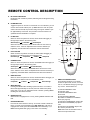
10
A. IR OUTPUT INDICATOR
Illuminates when a button is pressed, indicating that an IR signal is being
transmitted.
B. POWER BUTTON
Toggles the power on and off. For a discreet on or off command, you can
use the direct access buttons (see 'J'). Note: When the main AC power
switch is first turned ON, the processor will go through an initiation cycle
for approximately 15 seconds. The processor cannot be turned on or
operated until the initialization is complete.
C. UP BUTTON
When no menus are present on-screen, the UP button will toggle you
through aspect ratios in the following order:
Standard (4:3) Letterbox Anamorphic
When the menu is on-screen, the UP button will move the cursor up
within the menu. When an adjustment item has been selected (i.e.
brightness), the UP button will increase the value of that function.
D. LEFT BUTTON
When no menus are present on-screen, the LEFT button will toggle you
through the four different sources in the following order:
Pass-through Component S-Video Composite
E. DOWN BUTTON
When no menus are present on-screen, the DOWN button will toggle you
through aspect ratios in the following order:
Anamorphic Letterbox Standard (4:3)
When the menu is on-screen, the DOWN button will move the cursor
down within the menu. When an adjustment item has been selected (i.e.
brightness), the DOWN button will decrease the value of that function.
F. RIGHT BUTTON
When no menus are present on-screen, the RIGHT button will toggle you
through the four different sources in the following order:
Composite S-Video Component Pass-through
G. MENU BUTTON
Pressing the MENU button will bring up the main menu. If no action is
taken within approximately 10 seconds, the menu will time-out (disap-
pear). Also, if you are in an adjustment mode or function, pressing MENU
will bring the menu back one level.
H. ENTER BUTTON
When an item is highlighted on a menu, pressing ENTER will select that
item.
I. PROGRAM BUTTON
If the remote control loses its 'memory' as a result of weak or dead bat-
teries, it must be re-programmed for the PFP-7/PFP-11's code set. To
reprogram the remote, press the PROGRAM button followed by 0,1,3.
Note: Pressing Enter after typing in the code is not necessary.
M
A
B
C
D
E
J
F
G
H
I
12 3
45 6
78 9
I
N
P
U
T
0
N
P
U
T
I
OFF
ON
J. DIRECT ACCESS BUTTONS
These buttons will allow you to directly
access an aspect ratio, source, or turn the
unit on or off without having to go through
any menus. These buttons are:
1: Selects COMPOSITE video
2: Selects S-video
3: Selects COMPONENT video
4: Not used
5: Selects PASS-THROUGH
6: Enables or Disables the Installation
Menu (see page 18)
7: Selects the ANAMORPHIC aspect ratio
8: Selects the STANDARD (4:3) aspect
ratio
9: Selects the LETTERBOX aspect ratio
0: Turns the processor ON.
OFF: Also known as the button left of '0',
this turns the processor OFF.
REMOTE CONTROL DESCRIPTION

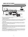
While there are many different ways to connect your source equipment to your PFP-7/PFP-11,
the examples shown above are the most common.
• COMPOSITE VIDEO INPUT:
Composite video is the most common type of signal used, but is also the lowest in picture quality. Many
sources have outputs that are limited to composite video, such as some VCR’s and camcorders; others
such as Laser Disc players actually produce slightly better results when using composite video.
• S-VIDEO INPUT
S-video is the second-best type of signal that can be used, but is MUCH better than composite video.
Using such sources as Satellite receivers, high-quality VCRs and DVD players (with no component
output) will produce a MUCH cleaner and sharper signal.
• COMPONENT INPUT
Component video is the best type of signal that can be used. The most common sources that use com-
ponent outputs are DVD players, and it is highly recommended that component be used when possible.
Component video goes one step beyond S-video in picture quality; chroma (color) information is more
resolved and the overall picture appears more well-defined.
• PASS-THROUGH
This input is used to ‘pass-through’ any high-definition or computer signals that do not require process-
ing. The signal by-passes the PFP-7/PFP-11’s processing and is sent directly to the display. The pass-
through may be used for COMPONENT outputs from a DTV decoder, a progressive-scan DVD player
or RGB outputs from a computer or other high-resolution sources.
11
QUICK SET-UP GUIDE
Connection Examples
12V TRIGGER
12V FUSE
RGB VIDEO OUTPUT VIDEO INPUTS
RS-232 IN
MADE IN USA
AC 120V 60Hz, 15W
RUNCO INTERNATIONAL
HAYWARD, CA
MASK
SCREEN
PASS THROUGH COMPOSITE
V
H
B G R Y Pr Pb S-VIDEO
Display Device
Computer or
DTV decoder
DVD Player
Sattelite
receiver or
SVHS player
VCR, Laser
disc player,
camcorders
R
UN
C
O
Reserved for
future use
Automation
System

12
Now that your PFP-7/PFP-11 has been installed, it's time to get it configured for use in your system.
Please follow the procedures and recommendations below:
1. First, connect all sources (DVD, VCR, Satellite receiver, etc.) to the PFP-7/PFP-11, if this has not already
been done. Also, ensure all sources are ON and functioning, if possible.
2. Connect the RGB (or component) output of the PFP-7/PFP-11 to the display device it is to be used with.
NOTE: It may be necessary to set the 'output format' and 'resolution' in the Installation menu to match the
input type and scan rate of the display device it is to be used with (see page 19).
3. With everything properly connected, turn the PFP-7/PFP-11 on, followed by the display device itself.
4. If the output scan rate and output format have not been optimized for the display device the processor will be
used with, set them now (see page 19 for recommendations).
5. Next, set the 'screen type' in the installation menu, either 16:9 screen (for installations using widescreens or
other display devices with a 16:9 aspect ratio (i.e. a plasma display)) or 4:3 screen for those displays using a
4:3 screen only.
Once the initial settings have been completed, the 'front panel settings' (color, tint, sharpness, etc.) can be
adjusted for each aspect ratio. The calibration procedures for these adjustments are outlined in 'picture quality
adjustments', page 15.
Getting Started

13
Overall Functional Description
The PFP-7/PFP-11 has many useful purposes. It has many different scan rate outputs that can match most fixed-
pixel displays, as well as most HD-capable rear-screen televisions. Also, the sync polarity and output type (RGB,
Component, Sync on green, etc.) can be changed to meet the requirements of the display device, ensuring that
the PFP-7/PFP-11 will be fully compatible in all respects to just about every type of display.
In addition to being compatible with most displays, it also includes aspect-ratio control. This is extremely beneficial
for those displays that do not have any type of aspect ratio control, as all movies can now be viewed in their native
format instead of having to settle for 4:3.
So, how does the PFP-7/PFP-11 work, anyways? In a nutshell, the PFP-7/PFP-11 is an advanced processor
known as a SCALER. A scaler takes the interlaced NTSC signal (such as that from a standard DVD player or
VCR, for example), de-interlaces it, and then scales it to one of many selectable resolutions.
It is the proprietary Vivix
TM
technology that gives the PFP-7/PFP-11 the ability to change not only scan rates or
resolutions, but aspect ratios as well.
As mentioned, the PFP-7/PFP-11 is compatible with many types of display devices. To ensure a display device is
capable of working with the PFP-7/PFP-11, it must have the following specifications:
• Capable of a horizontal scan rate of at least 31.5 KHz
• Capable of a resolution of at least 854 x 480 (480p)
• Can accept RGB (separate or composite syncs, or sync on green), or component signals
In addition, the processor is designed to work properly on widescreens with an aspect ratio of either 1.78:1 (16:9)
or 1.85:1, or any 4:3 screen. The processor is not designed to provide aspect ratio control for 2.35:1 screens.
For input signals, the PFP-7/PFP-11 can accept NTSC or PAL signals from most typical sources. This includes
interlaced signals from standard DVD players, Satellite receivers, VCRs, Laser Disc players, camcorders and
other similar equipment. For higher-resolution signals such as a computer, high-definition decoder or progressive
DVD players, these signals MUST be connected to the Pass-through port. The PFP-7/PFP-11 will not accept pro-
gressive signals on its Component input port (i.e. progressive DVD players).
Ensure that your display device is compatible with any high-resolution signal you input to the pass-through port.
NOTE: The PFP-7/PFP-11 will not process any signal on its pass-through port; it will simply loop the signal directly
to its output. Also, the pass-through port will not convert component signals to RGB signals; component signals
input to the pass-through port will be output as component signals.
NOTE: The PFP-7/PFP-11 will not accept PAL signals for the 854 x 480, 480p or 540p
resolutions. All other resolutions are both NTSC/PAL compatible.
Compatibility

14
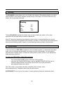
When the MENU button is pressed on either the remote control or the front panel, the main menu will
appear on-screen. An example of the main menu is shown above.
The active source is indicated by an arrow to the left of the source; note that in the example above,
Composite is the current source.
To select a source via the main menu, press either the up or down buttons on the remote or front
panel and highlight the desired source, and press ENTER. Otherwise, you may select a source by
pressing either the left or right arrow buttons (on the remote or front panel) when no menus are
on-screen, or by pressing one of the direct access buttons on the remote control
(recommended; see page 10).
If pass-through is selected, note that no on-screen menus will be displayed since the signal is simply
being 'looped' directly to the output. When pass-through is the selected source, pressing MENU will
automatically select the last selected input before Pass-through was selected. If you wish to choose
another source, Runco recommends using the direct access buttons to select the desired source as
opposed to pressing MENU.
Aspect Ratio provides selection of one of three aspect ratios: Anamorphic, Letterbox or standard 4:3.
To select an aspect ratio via the main menu, press either the up and down buttons on the remote or
front panel, highlight ASPECT RATIO and press ENTER. The aspect ratio menu will then appear with
the three choices; highlight the desired aspect ratio with the up or down buttons and press ENTER.
Otherwise, you may select an aspect ratio by pressing either the up or down arrow buttons (on the
remote or front panel) when no menus are on-screen, or by pressing one of the direct access buttons
on the remote control (recommended; see page 10).
Installation is where the scan rate and sync types can be adjusted, as well as screen types,
'side bar' levels, image shift and blanking controls. A full description of this menu is on page 18.
NOTE: If INSTALLATION does not appear on the main menu, see page 18 for an explanation on how
to access the Installation menu.
MENU DESCRIPTION AND NAVIGATION
Main Menu
MAIN MENU
>
COMPOSITE
S-VIDEO
COMPONENT
PASS THROUGH
ASPECT RATIO
INSTALLATION
Source selection and
picture quality adjustments
See "installation" section
Aspect ratio selection

Picture quality adjustments (also known as "Front Panel Controls") are the controls that change different
parameters of the image such as the amount of color, black level, etc. While these adjustments can be set to suit
the needs of the user, there is a way to set these properly. This section will describe what each function does and
how to adjust them properly.
To access the picture quality adjustments, press MENU, highlight the active source (indicated by the arrow) and
press ENTER. The picture quality sub-menu will then appear (see above).
To make an adjustment to a particular function, highlight the function with the up or down arrow buttons and press
ENTER. Once the function is on-screen (i.e. brightness), pressing the UP arrow button on the remote or front
panel will increase the value of that function; pressing the DOWN arrow on the remote or front panel will decrease
the value of that function.
While each of the picture quality adjustments can be set to suit the needs of the user, there is a 'proper' way to set
the adjustments. For setting TINT and COLOR, please refer to the color bar test pattern below.
NOTE: For many display devices, a BLUE FILTER must be used so only the blue color bars can be seen; if no
blue color filter is available, see if the display device has the ability to mute (turn off) the red and green
colors via its menu structure (most CRT projectors have this feature). Blue filters are provided with the Video
Essentials or AVIA test DVDs, or can be purchased from the Imaging Science Foundation
(www.imagingscience.com).
15
MAIN MENU
>
COMPOSITE
S-VIDEO
COMPONENT
PASS THROUGH
ASPECT RATIO
INSTALLATION
TINT
COLOR
BRIGHTNESS
CONTRAST
SHARPNESS
LUMA ENHANCE
CHROMA ENHANCE
Picture Quality Adjustments
Tall color bars
Short color bars
Tint
Color
white
yellow
cyan
green
magenta
red
blue

16
TINT (also known as 'hue') is essentially the ratio of red to green in the color portion of the image.
If TINT is decreased, the image will appear redder, and increasing it will cause the image to appear
greener. To set TINT properly, look at the color bar pattern through a blue filter (or mute the red and
green outputs). Adjust TINT until the middle two tall color bars match the middle short color bars
(see color bar drawing).
COLOR (also known as 'saturation') increases or decreases the amount of color in the image. To set
COLOR properly, look at the color bar pattern through a blue filter (or mute the red and green outputs).
Adjust COLOR until the outer two tall color bars match the outer short color bars
(see color bar drawing).
For setting CONTRAST and BRIGHTNESS, please refer to the PLUGE pattern below:
CONTRAST adjusts the white level of the image. To adjust this properly for CRT projectors, adjust
CONTRAST until there is no blooming (or distortion) in the brightest bar in the PLUGE pattern (see
above). For Fixed-pixel displays, adjust contrast until there is a distinct definition between the two
brightest bars.
NOTE: For best results, Runco recommends that CONTRAST be set to '0' or very close to it.
BRIGHTNESS adjusts the black level of the image. To adjust this properly, adjust BRIGHTNESS until
the 'below black' bar JUST disappears, but the 'above black' bar is still barely visible.
NOTE: Some DVD players cannot pass the 'blacker than black' bar (they won't pass PLUGE), and that
bar will never be visible. In a case like this, adjust the 'above black' bar until it is slightly brighter than
the background that surrounds it.
Below black
Above black
Set contrast
untill there is
no 'blooming'
in this bar.

SHARPNESS adjusts the amount of high-frequency detail in the image. This can be adjusted to the
preference of the user. Keep in mind that when SHARPNESS is decreased, fine details in the image will
become 'soft'; when it is increased, fine details will become sharper but will also make the picture
appear 'noisy' if adjusted too high.
LUMA ENHANCE acts as an edge enhancement, especially around black to white transitions in the
image. Essentially, this has the same characteristics as sharpness but affects the edges of objects far
more that the rest of the image.
FREQUENCIES HIGH/LOW affect the overall range of the LUMA ENHANCE feature. For example, if
using a lower-quality video source such as a VCR, the FREQUENCIES should be set to LOW. For a
good quality source such as a DVD player, set FREQUENCIES to HIGH. To set FREQUENCIES, press
ENTER while LUMA ENHANCE is on-screen.
CHROMA ENHANCE acts as an edge enhancement, especially around color transitions in the image.
Essentially, this has the same characteristics as sharpness but affects the edges of objects far more
that the rest of the image.
FREQUENCIES HIGH/LOW affect the overall range of the CHROMA ENHANCE feature. For example,
if using a lower-quality video source such as a VCR, the FREQUENCIES should be set to LOW. For a
good quality source such as a DVD player, set FREQUENCIES to HIGH. To set FREQUENCIES, press
ENTER while CHROMA ENHANCE is on-screen.
17
The Installation menu is where you can adjust the scan rate and sync type, as well as set the type of
screen (4:3 or 16:9), shift the image or set blanking, and even set the level of the 'sidebars'.
When the PFP-7/PFP-11 is turned on for the first time, the INSTALLATION item will not appear in the
main menu. To enable the INSTALLATION menu, there are two options:
· With the processor ON and no menus on-screen, simultaneously press the ENTER, UP and LEFT
buttons (you don't need to hold them down). Release the three buttons and press MENU, ensure
INSTALLATION is now on the bottom of the main menu.
· With the remote control, press button 6 (with no menus on-screen).
After pressing '6', press MENU and ensure INSTALLATION is now on the bottom of the main menu.
After INSTALLATION has been accessed, press MENU, highlight INSTALLATION and press ENTER.
This will bring up the INSTALLATION MENU, shown below:
Installation Menu
INSTALLATION
4:3 SCREEN
16:9 SCREEN
RESOLUTION
OUTPUT FORMAT
SIDE BAR LEVEL
IMAGE SHIFT
BLANKING
>

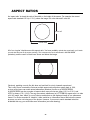
When you are installing the processor for the first time, the first order of business is to define what type of
screen will be used with this system. If a 1.78:1 (16:9) or 1.85:1 screen is used, highlight 16:9 SCREEN and
press ENTER. If a standard 4:3 screen is installed, highlight 4:3 SCREEN and press enter. However, if your
display is a native 16:9 aspect ratio (such as most plasmas), you only need to select the actual resolution of
the device. The PFP-7/PFP-11 will automatically switch itself to the proper mode.
The purpose of defining the screen type is to tell the processor how to create aspect ratios (see page 27 for
a definition of aspect ratios). For example, on a 16:9 screen, the letterbox and anamorphic aspect ratios will
use the entire 16:9 screen, and the 4:3 aspect ratio will be displayed in the center of the 16:9 screen (you'd
have 'black bars' on the left and right sides of the image).
On the other hand, on a 4:3 screen, the 4:3 aspect ratio would fill the screen, but the letterbox and
anamorphic aspect ratios would be displayed in the center of the screen vertically (there would be 'black
bars' on the top on bottom of the image).
Important note on aspect ratios for 4:3 screens: If 4:3 SCREEN is selected, the only way the processor
will provide all three aspect ratios is if one of the FIXED PIXEL scan rates are selected
(i.e. 1024 x 768). The processor will NOT provide three aspect ratios on a 4:3 screen if 480p, 540p, 600p or
720p are selected. The reason for this is that CRT projectors will provide the best resolution if two separate
memories are created by the projector itself, one for anamorphic, one for full 4:3. This way, the CRT projec-
tor can provide the maximum number of lines of resolution on either aspect ratio since it is simply compress-
ing a 4:3 image to an anamorphic image. Therefore, Runco recommends that the CRT projector create the
aspect ratios on 4:3 screens (if possible) for best results.
For fixed pixel displays, the number of pixels cannot be changed nor do many of the displays provide the
ability to create aspect ratios. Therefore, the PFP-7/PFP-11 will provide three full aspect ratios for fixed pixel
displays (WHEN a fixed-pixel scan rate is selected) for use on 4:3 screens.
In any event, if 16:9 SCREEN is selected, the PFP-7/PFP-11 will provide three aspect ratios regardless of
the selection of the scan rate type or display device used.
SCAN RATE is how many lines of resolution can be output in a single image. For example, 540p means that
there are 540 visible lines of resolution, and 'p' means the signal is PROGRESSIVE. A Progressive output is
where ALL lines of resolution will be displayed during each frame as opposed to an INTERLACED signal,
which only displays half the lines of the frame during one field and the other half the next. Progressive
outputs are far better than Interlaced outputs as all lines of resolution are always displayed, and fixed-pixel
displays produce far better results when using a progressive signal. The fixed-pixel outputs are also progres-
sive, but are referred to in PIXELS (Picture Elements) as opposed to the actual number of lines of resolution.
This is because fixed-pixel displays are referred to in their native resolution in pixels, i.e. 1024 x 768
(meaning 1024 vertical rows of pixels and 768 horizontal rows of pixels).
Selecting a scan rate (resolution) for your display device is an extremely important task. The first thing that
should be done is to determine what resolution will provide the best results for your display. The following
are some guidelines that will assist you in determining the best possible results for your type of projector.
18
Screen Type
Scan Rate/Resolution

To select a scan rate, first determine which type of display will be used with the PFP-7/PFP-11
(see 'Fixed pixel displays' or 'CRT displays' below). If the display is a FIXED PIXEL display, you'll want
to use one of the FIXED PIXEL scan rates. If using a CRT projector, you'll want to use one of the CRT
scan rates.
T
o select a resolution, follow this procedure:
· Press MENU and ensure 'INSTALLATION' is on the bottom of the menu. If it's not, enable the
INSTALLATION menu using the procedures on page 17.
· Using the up or down arrow buttons, highlight INSTALLATION and press ENTER.
· Once the INSTALLATION menu is on-screen, use the up or down arrow buttons to highlight SCAN
RATE and press ENTER.
· Note that at the top of the SCAN RATE menu that it will say either "PROGRESSIVE" or
"SCAN RATE-FIXED PIXEL"; if it indicates the wrong mode for your system (i.e. you have a CRT
projector but the menu says "FIXED PIXEL"), simply highlight the word "MORE…" on the bottom of
the menu and press ENTER. This will toggle you to the appropriate scan rate type for your display.
· Next, highlight the desired SCAN RATE and press ENTER. The PFP-7/PFP-11 will immediately go to
that scan rate. To confirm your scan rate selection, you must press MENU within ten seconds or the
processor will revert to the scan rate it was at before you made the selection.
Runco recommends that you ensure your display device produces an image before confirming the
scan rate. If it does not, allow the processor to revert to its previous scan rate and consult the
owner's manual of your display to see what it's scan rate or resolution capabilities are.
SCAN RATE menus:
Note that the arrow indicates the currently selected scan rate (854 x 480, in this example):
19
Selecting A Resolution (Scan Rate)
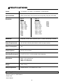
4:3 Device
800 x 600
1024 x 768
16:9 Device
854 x 480
1280 x 720
1280 x 768
1024 x 1024
More...
4:3 Device
800 x 600
1024 x 768
1280 x 1024
1366 x 1024
16:9 Device
854 x 480
1280 x 720
1280 x 768
1366 x 768
1024 x 1024
More...
PFP-7 PFP-11
Fixed Pixel Resolutions CRT Scan Rates Fixed Pixel - 4:3 Device CRT Scan Rates
Progressive
480p
540p
600p
720p
More...
Progressive
480p
540p
600p
720p
More...
>
>
Page is loading ...
Page is loading ...
Page is loading ...
Page is loading ...
Page is loading ...
Page is loading ...
Page is loading ...
Page is loading ...
Page is loading ...
Page is loading ...
Page is loading ...
Page is loading ...
Page is loading ...
Page is loading ...
-
 1
1
-
 2
2
-
 3
3
-
 4
4
-
 5
5
-
 6
6
-
 7
7
-
 8
8
-
 9
9
-
 10
10
-
 11
11
-
 12
12
-
 13
13
-
 14
14
-
 15
15
-
 16
16
-
 17
17
-
 18
18
-
 19
19
-
 20
20
-
 21
21
-
 22
22
-
 23
23
-
 24
24
-
 25
25
-
 26
26
-
 27
27
-
 28
28
-
 29
29
-
 30
30
-
 31
31
-
 32
32
-
 33
33
-
 34
34


Runco Projector Vivix Pixel for Pixel User manual
- Category
- Plasma TVs
- Type
- User manual
- This manual is also suitable for
Ask a question and I''ll find the answer in the document
Finding information in a document is now easier with AI
Related papers
Other documents
-
Voyager AOM561 User manual
-
Extron IN1401 User manual
-
Furman M1500-UPS-PFP Owner's manual
-
Tyco Entuitive 1229L User manual
-
Toshiba 4511 User manual
-
-
-
Graco 3A2776D Owner's manual
-
Toshiba e-Studio160 User manual
-