Sony VPL-VW90ES User manual
- Category
- Data projectors
- Type
- User manual
This manual is also suitable for

Operating Instructions
VPL-VW90ES
© 2010 Sony Corporation
4-262-154-11 (1)
Video Projector

2
To reduce the risk of fire or
electric shock, do not expose
this apparatus to rain or
moisture.
To avoid electrical shock, do
not open the cabinet. Refer
servicing to qualified
personnel only.
THIS APPARATUS MUST BE
EARTHED.
Afin de réduire les risques
d’incendie ou d’électrocution,
ne pas exposer cet appareil à
la pluie ou à l’humidité.
Afin d’écarter tout risque
d’électrocution, garder le
coffret fermé. Ne confier
l’entretien de l’appareil qu’à
un personnel qualifié.
CET APPAREIL DOIT ÊTRE
RELIÉ À LA TERRE.
Um die Gefahr von Bränden
oder elektrischen Schlägen zu
verringern, darf dieses Gerät
nicht Regen oder Feuchtigkeit
ausgesetzt werden.
Um einen elektrischen Schlag
zu vermeiden, darf das
Gehäuse nicht geöffnet
werden. Überlassen Sie
Wartungsarbeiten stets nur
qualifiziertem Fachpersonal.
DIESES GERÄT MUSS
GEERDET WERDEN.
For the customers in the U.S.A. and
Canada
WARNING:
Using this unit at a voltage other than 120 V
may require the use of a different line cord or
attachment plug, or both. To reduce the risk
of fire or electric shock, refer servicing to
qualified service personnel.
For the customers in the U.S.A.
This equipment has been tested and found to
comply with the limits for a Class B digital
device, pursuant to Part 15 of the FCC
Rules. These limits are designed to provide
reasonable protection against harmful
interference in a residential installation. This
equipment generates, uses, and can radiate
radio frequency energy and, if not installed
and used in accordance with the instructions,
may cause harmful interference to radio
communications. However, there is no
guarantee that interference will not occur in
a particular installation. If this equipment
does cause harmful interference to radio or
television reception, which can be
determined by turning the equipment off and
on, the user is encouraged to try to correct
the interference by one or more of the
following measures:
- Reorient or relocate the receiving antenna.
- Increase the separation between the
equipment and receiver.
- Connect the equipment into an outlet on a
circuit different from that to which the
receiver is connected.
- Consult the dealer or an experienced
radio/TV technician for help.
You are cautioned that any changes or
modifications not expressly approved in this
manual could void your authority to operate
this equipment.
WARNING
AVERTISSEMENT
WARNUNG

3
All interface cables used to connect
peripherals must be shielded in order to
comply with the limits for a digital device
pursuant to Subpart B of Part 15 of FCC
Rules.
If you have any questions about this product,
you may call;
Sony Customer Information Service Center
1-800-222-7669 or http://www.sony.com/
For the State of California, USA only
Perchlorate Material - special handling may
apply, See www.dtsc.ca.gov/
hazardouswaste/perchlorate
Perchlorate Material : Lithium battery
contains perchlorate.
For the customers in Canada
This Class B digital apparatus complies with
Canadian ICES-003.
Pour les clients au Canada
Cet appareil numérique de la classe B est
conforme à la norme NMB-003 du Canada.
For the customers in Europe
The manufacturer of this product is Sony
Corporation, 1-7-1 Konan, Minato-ku,
Tokyo, 108-0075 Japan.
The Authorized Representative for EMC
and product safety is Sony Deutschland
GmbH, Hedelfinger Strasse 61, 70327
Stuttgart, Germany. For any service or
guarantee matters please refer to the
addresses given in separate service or
guarantee documents.
Pour les clients en Europe
Le fabricant de ce produit est Sony
Corporation, 1-7-1 Konan, Minato-ku,
Tokyo, 108-0075 Japon.
Le représentant autorisé pour EMC et la
sécurité des produits est Sony Deutschland
GmbH, Hedelfinger Strasse 61, 70327
Stuttgart, Allemagne. Pour toute question
concernant le service ou la garantie, veuillez
consulter les adresses indiquées dans les
documents de service ou de garantie séparés.
Für Kunden in Europa
Der Hersteller dieses Produkts ist Sony
Corporation, 1-7-1 Konan, Minato-ku,
Tokyo, 108-0075 Japan.
Der autorisierte Repräsentant für EMV und
Produktsicherheit ist Sony Deutschland
GmbH, Hedelfinger Strasse 61, 70327
Stuttgart, Deutschland. Bei jeglichen
Angelegenheiten in Bezug auf
Kundendienst oder Garantie wenden Sie
sich bitte an die in den separaten
Kundendienst- oder Garantiedokumenten
aufgeführten Anschriften.
For kundene i Norge
Dette utstyret kan kobles til et IT-
strømfordelingssystem.
Für Kunden in Deutschland
Entsorgungshinweis: Bitte werfen Sie nur
entladene Batterien in die Sammelboxen
beim Handel oder den Kommunen. Entladen
sind Batterien in der Regel dann, wenn das
Gerät abschaltet und signalisiert „Batterie
leer“ oder nach längerer Gebrauchsdauer der
Batterien „nicht mehr einwandfrei
funktioniert“. Um sicherzugehen, kleben Sie
die Batteriepole z.B. mit einem
Klebestreifen ab oder geben Sie die
Batterien einzeln in einen Plastikbeutel.
Declaration of Conformity
Trade Name: SONY
Model: VPL-VW90ES
Responsible party: Sony Electronics Inc.
Address: 16530 Via Esprillo,
San Diego, CA 92127
U.S.A.
Telephone Number:858-942-2230
This device complies with part 15 of the
FCC Rules. Operation is subject to the
following two conditions: (1) this device
may not cause harmful interference, and
(2) this device must accept any interference
received, including interference that may
cause undesired operation.

4
For the customers in Taiwan only

5
Table of Contents
Precautions .........................................7
Front/Right Side .................................8
Rear/Bottom .......................................9
Remote Control ................................10
3D Glasses ........................................11
Unpacking ........................................12
Step 1: Installing the Projector .........13
Before Setting Up the
Projector .....................................13
Positioning the Projector and a
Screen .........................................15
Step 2: Adjusting the Picture
Position .............................................19
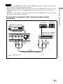
Step 3: Connecting the Projector .....24
Connecting to a VCR .................24
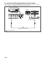
Connecting to a Computer ..........27
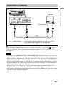
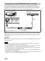
Connecting to an Optional TMR-
BR100 3D Sync Transmitter ......28
Step 4: Selecting the Menu
Language ..........................................29
Projecting the Picture on the
Screen .............................................. 31
Turning Off the Power ............... 32
Operating the BRAVIA Sync
Compatible Equipment with the
Remote Control of the Projector ...... 33
Selecting the Wide Screen Mode .... 35
Watching 3D Video Images ............ 38
Using the Simulated 3D
Function ..................................... 39
Using the 3D Glasses ................. 40
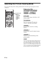
Selecting the Picture Viewing
Mode ............................................... 42
Adjusting the Picture Quality .......... 43
Selecting to Directly Adjust the
Desired Menu Item .................... 43
Selecting Desired Adjust Menu
Items in the Order ...................... 44
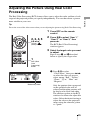
Adjusting the Picture Using Real Color
Processing ........................................ 45
Using the Supplied Software to Adjust
the Picture Quality
(ImageDirector3) ............................. 46
Operation through the Menus .......... 47
Picture Menu ................................... 51
Advanced Picture Menu .................. 56
Screen Menu .................................... 57
Setup Menu ...................................... 59
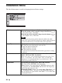
Function Menu ................................. 61
Installation Menu ............................. 64
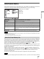
Information Menu ............................ 67
Location of Controls
Connections and
Preparations
Projecting
Using the Menus

6
About the Preset Memory No. ... 67
About the Control for HDMI ........... 68
About the x.v.Color ......................... 69
About the simulated 3D feature ....... 69
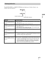
Troubleshooting ............................... 70
Warning Indicators ..................... 73
Message Lists ............................. 74
Replacing the Lamp and the Air Filter
and Cleaning the Ventilation Holes
(intake) ............................................. 76
Cleaning the Air Filter ..................... 79
Cleaning and the Screen of the
Projector ........................................... 79
Replacing the Battery of the 3D
Glasses ............................................. 80
Removing/Attaching the Filter
Attachment for 3D Glasses .............. 82
Specifications ................................... 84
Preset Signals ............................. 86
Input Signals and Adjustable/
Setting Items ............................... 89
Compatible 3D Signals .............. 91
3D Signals and Adjustable/Setting
Items ......................................... 91
Ceiling Installation ...........................93
Index ............................................... 97
Others
Trademark Information
“PS3” is a registered trademark of Sony
Computer Entertainment Inc.
HDMI, the HDMI logo and High-Definition
Multimedia Interface are trademarks or
registered trademarks of HDMI Licensing
LLC.
“Blu-ray” and “Blu-ray Disk” are
trademarks of Blu-ray Disc Association.
..........................................................................
Control for HDMI is an HDMI standard mutual
control function which uses the HDMI CEC
(Consumer Electronics Control) specification.
This projector supports DeepColor, x.v.Color,
LipSync, 3D signal and computer input signal
of HDMI standards. It also supports HDCP.

7
Precautions
On safety
• Check that the operating voltage of your
unit is identical with the voltage of your
local power supply.
• Should any liquid or solid object fall into
the cabinet, unplug the unit and have it
checked by qualified personnel before
operating it further.
• Unplug the unit from the wall outlet if it is
not to be used for several days.
• To disconnect the cord, pull it out by the
plug. Never pull the cord itself.
• The wall outlet should be near the unit and
easily accessible.
• The unit is not disconnected to the AC
power source (mains) as long as it is
connected to the wall outlet, even if the
unit itself has been turned off.
• Do not look into the lens while the lamp is
on.
• Do not place your hand or objects near the
ventilation holes. The air coming out is
hot.
On preventing internal heat build-
up
After you turn off the power with the ?/1
(ON/STANDBY) switch, do not disconnect
the unit from the wall outlet while the
cooling fan is still running.
Caution
The projector is equipped with ventilation
holes (intake) and ventilation holes
(exhaust). Do not block or place anything
near these holes, or internal heat build-up
may occur, causing picture degradation or
damage to the projector.
On repacking
Save the original shipping carton and
packing material; they will come in handy if
you ever have to ship your unit. For
maximum protection, repack your unit as it
was originally packed at the factory.

8
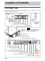
Front/Right Side
You can use the buttons on the control panel with the same names as those on the remote
control to operate the projector.
Location of Controls
INPUT button (1 page 31)
MENU button (1 page 47)
ON/STANDBY
indicator
(1 page 19)
Remote control detector
Ventilation
holes (exhaust)
(1 page 14)
?/1 (ON/STANDBY) switch (1 page 20)
LAMP/COVER
indicator
(1 page 73)
M/m/</, (arrow)/
(enter) button (1 page 47)
Ventilation holes (exhaust) (1 page 14)
- AC IN socket
VIDEO INPUT connector (phono type) (1 page 26)
Y P
B/CB PR/CR connector (phono type) (1 page 24)
INPUT A connector (1 page 27)
HDMI 1 connector (1 page 24)
REMOTE
connector
Connects to a
computer, etc.
for remote
control.
(1 page 46)
HDMI 2 connector (1 page 24)
While the ON/STANDBY indicator
lights in orange, the power saving
mode is on. (1 page 60)
Note
Control panel
LENS button (1 page 19)
Open button
IR IN connector Inputs signals to control the projector
TRIGGER connector (1 page 36)
Press the button and open
the cover.
Lens protector
3D Sync Transmitter
3D SYNC connector (1 page 28)

9
Location of Controls
Rear/Bottom
Filter holder (1 page 78)
Ventilation holes (intake)
(1 page 14)
Lamp cover (1 page 77)
Ventilation holes (intake)
(1 page 14)
Projector suspension
support attaching hole
(1 page 93)
Adjusters (1 page 23)
Ventilation holes (intake)
(1 page 14)
Ventilation holes (intake)
(1 page 14)
Ventilation holes (intake)
(1 page 14)
Remote control detector
(1 page 19)

10
Remote Control
Infrared transmitter
?/1 (On/standby)
switch (1 page 20)
COLOR SPACE button
(1 page 43)
M/m/</, (arrow)/
(enter) buttons
(1 page 47)
RESET button
(1 page 47)
MOTION ENHANCER
button (1 page 43)
CONTRAST +/– button
(1 page 52)
BRIGHTNESS +/– button
(1 page 53)
INPUT button
(1 page 31)
LIGHT button
Illuminates the buttons on
the remote control.
PICTURE MODE buttons
(1 page 42)
ADJ PIC (Adjust Picture)
button (1 page 44)
WIDE MODE button
(1 page 35)
Buttons to operate
BRAVIA Sync compatible
equipment (1 page 33)
LENS button
(1 page 19)
SHARPNESS +/– button
(1 page 53)
MENU button
(1 page 47)
ADVANCED IRIS button
(1 page 43)
COLOR TEMP button
(1 page 43)
RCP (Real Color
Processing) button
(1 page 45)
BLACK LEVEL button
(1 page 43)
GAMMA CORRECTION
button (1 page 43)
FILM PROJECTION
button (1 page 43)

11
Location of Controls
3D Glasses
1 Slide switch
Set the switch for a comfortable fit (1
page 40).
2 Battery cover
Detach the cover when replacing the
battery (1 page 80).
3 LED indicator
Flashes one time every 3 seconds: Power
on
Flashes three times every 3 seconds:
Low battery. Battery capacity is almost
running out.
Flashes three times: Power off
4 IR sensor
Receive signals from the 3D Sync
Transmitter.
IR’s entry angle differs according to
distance or usage environment.
Please keep this face clean.
5 Filter attachment
Filters are attached to view the 3D video
images.
Do not remove the filters. You cannot view
the 3D video images without them.
6 Power button
Power on: Press once
Power off: Hold power button down for
2 seconds
* Auto power off: More than 5 minutes
without IR signal
7 Nose pad
Adjust the nose pad for a comfortable fit.
8 Temple frames
You can bend (adjust) the temple frames
for a comfortable fit.
Note
Before use: Remove
the battery’s insulating
sheet before using the
product for the first time.
This part receives IR
(infrared rays) from the
3D Sync Transmitter.
Note

12
This section describes how to install the projector and screen, how to connect the
equipment from which you want to project the picture, etc.
Unpacking
Check the carton to make sure it contains the following items:
Inserting the batteries into the remote control
CAUTION
Danger of explosion if battery is incorrectly replaced.
Replace only with the same or equivalent type recommended by the manufacturer.
When you dispose of the battery, you must obey the law in the relative area or country.
Installing batteries
Two size AA (R6) batteries are supplied for Remote Control.
To avoid risk of explosion, use size AA (R6) manganese or alkaline batteries.
Caution about handling the remote control
• Handle the remote control with care. Do not drop or step on it, or spill liquid of any kind
onto it.
• Do not place the remote control in a location near a heat source, a place subject to direct
sunlight, or a damp room.
Connections and Preparations
• Remote control (1) and
Size AA (R6) manganese batteries (2)
• AC power cord (1)
• ImageDirector3 CD-ROM (1)
• Operating Instructions (this manual) (1)
• 3D glasses (including the batteries) (2)
• Pouch for the 3D glasses (2)
• Filter attachments for the 3D glasses
(For the customers in the U.S.A.)
Regular size (4 kits)
Small size (4 kits)
(For the customers in other countries and
regions)
Regular size (2 kits)
Small size (2 kits)
• Conversion cable (RJ45 y 3D SYNC) (1)
Insert the batteries
E
side first as shown in the illustration.
Inserting them forcibly or with the polarities reversed may
cause a short circuit and may generate heat.
Push and slide to open.

13
Connections and Preparations
Step 1: Installing the Projector
The projector displays pictures output from
a VCR or other device.
The lens shift allows you to have broader
options for placing the projector and
viewing pictures easily.
Unsuitable installation
Do not place the projector in the following
situations, which may cause malfunction
or damage to the projector.
Poorly ventilated location
Leave space of more than 30 cm (11
7
/
8
inches)
around the unit.
Hot and humid
Locations subject to direct cool or
warm air from an air-conditioner
Installing the projector in such a location
may cause a malfunction of the unit due to
moisture condensation or rise in
temperature.
Near a heat or smoke sensor
Malfunction of the sensor may occur.
Very dusty and extremely smoky
locations
Install in a location away from walls
To maintain the performance and
reliability of the projector, allow at
least 30 cm (11 7/8 inches) between
the projector and walls.
Before Setting Up the
Projector
30 cm
(11
7
/
8
inches)
30 cm
(11
7
/
8
inches)
30 cm
(11
7
/
8
inches)
30 cm
(11
7
/
8
inches)

14
Improper use
Do not do any of the following while using
the projector.
Blocking the ventilation holes (intake
or exhaust)
Tip
For details on the location of the ventilation
holes (intake or exhaust), see “Location of
Controls” on page 8.
Tilting front/rear and left/right
Avoid using the projector tilted at an angle
of more than 15 degrees.
Do not install the projector anywhere other
than on a level surface or on the ceiling.
Installing the projector in such a location
may result in uneven color uniformity or
reduce the reliability of the effects of the
lamp.
When installing the unit at high
altitudes
When using the projector at an altitude of
1,500 m or higher, set “Cooling Setting” on the
Setup menu to “High” (1 page 59).
Failing to set this mode when using the
projector at high altitudes could have adverse
effects, such as reducing the reliability of
certain components.
WARNING
When installing the unit, incorporate a readily
accessible disconnect device in the fixed
wiring, or connect the power plug to an easily
accessible socket-outlet near the unit. If a fault
should occur during operation of the unit,
operate the disconnect device to switch the
power supply off, or disconnect the power
plug.
Ventilation holes
(exhaust)
Ventilation holes
(intake)
15° or more
15° or more
15° or more
15° or more
15° or more

15
Connections and Preparations
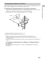
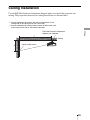
The installation distance between the projector and a screen varies depending on the size
of the screen or whether or not you use the lens shift features.
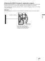
1 Determine the installation position of the projector and screen.
You can obtain a good quality picture if you position the projector so that the center
of the lens is within the area indicated in gray in the illustration.
Use the values L, x and y in the table on page 16 or 17 as a guide.
* Installation position not using lens shift (x = 0, y = 0)
** Example of installation position using lens shift (x, y)
L: Distance between the screen and the front end of the projector’s lens.
x: Horizontal distance between the center of the screen and the center of the
projector’s lens.
y: Vertical distance between the center of the screen and the center of the projector’s
lens.
For installation of the projector on a ceiling, see “Ceiling Installation.”
(1 page 93)
For details on the lens shift feature, see “Step 2: Adjusting the Picture Position”
(1 page 19).
Positioning the Projector and a Screen
Screen
*
**

16
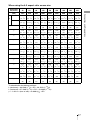
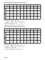
When using the 16:9 aspect ratio screen size
Unit: mm (inches)
To calculate the installation positions
L (minimum) = 31.1781 (1
7
/
32
) × SS – 46.1543 (1
13
/
16
)
L (maximum) = 47.0644 (1
27
/
32
) × SS – 42.3308 (1
21
/
32
)
y = –1.463 × x (mm or inch) + 8.0942 (
5
/
16
) × SS
Screen Size
SS (inches)
40 60 80 100 120 150 200 250 300
(mm) 1016 1524 2032 2540 3048 3810 5080 6350 7620
L
minimum 1201 1825 2448 3072 3695 4631 6189 7748 9307
(47
3
/
8
) (71
7
/
8
) (96
1
/
2
) (121) (145
1
/
2
) (182
3
/
8
) (243
3
/
4
) (305
1
/
8
) (366
1
/
2
)
maximum 1840 2782 3723 4664 5605 7017 9371 11724 14077
(72
1
/
2
) (109
5
/
8
) (146
5
/
8
) (183
5
/
8
) (220
3
/
4
) (276
3
/
8
) (369) (461
5
/
8
) (554
1
/
4
)
x 000000000
(0) (0) (0) (0) (0) (0) (0) (0) (0)
y 324 486 648 809 971 1214 1619 2024 2428
(12
7
/
8
) (19
1
/
4
)(25
5
/
8
) (31
7
/
8
) (38
1
/
4
) (47
7
/
8
)(63
3
/
4
) (79
3
/
4
) (95
5
/
8
)
x 44 66 89 111 133 166 221 277 332
(1
3
/
4
) (2
5
/
8
) (3
5
/
8
) (4
3
/
8
)(5
1
/
4
) (6
5
/
8
) (8
3
/
4
) (11) (13
1
/
8
)
y 259 389 518 648 777 971 1295 1619 1943
(10
1
/
4
) (15
3
/
8
)(20
1
/
2
) (25
5
/
8
) (30
5
/
8
) (38
1
/
4
) (51) (63
3
/
4
) (76
1
/
2
)
x 89 133 177 221 266 332 443 553 664
(3
5
/
8
) (5
1
/
4
) (7) (8
3
/
4
) (10
1
/
2
) (13
1
/
8
)(17
1
/
2
) (21
7
/
8
) (26
1
/
4
)
y 194 291 389 486 583 728 971 1214 1457
(7
3
/
4
) (11
1
/
2
)(15
3
/
8
) (19
1
/
4
) (23) (28
3
/
4
)(38
1
/
4
) (47
7
/
8
) (57
3
/
8
)
x 133 199 266 332 398 498 664 830 996
(5
1
/
4
) (7
7
/
8
)(10
1
/
2
) (13
1
/
8
) (15
3
/
4
) (19
5
/
8
)(26
1
/
4
) (32
3
/
4
) (39
1
/
4
)
y 130 194 259 324 389 486 648 809 971
(5
1
/
8
) (7
3
/
4
)(10
1
/
4
) (12
7
/
8
) (15
3
/
8
) (19
1
/
4
)(25
5
/
8
) (31
7
/
8
) (38
1
/
4
)
x 177 266 354 443 531 664 886 1107 1328
(7) (10
1
/
2
) (14) (17
1
/
2
) (21) (26
1
/
4
) (35) (43
5
/
8
) (52
3
/
8
)
y 65 97 130 162 194 243 324 405 486
(2
5
/
8
) (3
7
/
8
) (5
1
/
8
) (6
1
/
2
)(7
3
/
4
) (9
5
/
8
)(12
7
/
8
) (16) (19
1
/
4
)
x 221 332 443 553 664 830 1107 1384 1660
(8
3
/
4
) (13
1
/
8
)(17
1
/
2
) (21
7
/
8
) (26
1
/
4
) (32
3
/
4
)(43
5
/
8
) (54
1
/
2
) (65
3
/
8
)
y 000000000
(0) (0) (0) (0) (0) (0) (0) (0) (0)

17
Connections and Preparations
When using the 4:3 aspect ratio screen size
Unit: mm (inches)
To calculate the installation positions
L (minimum) = 38.1569 (1
1
/
2
) × SS – 46.1543 (1
13
/
16
)
L (maximum) = 57.5992 (2
9
/
32
) × SS – 42.3308 (1
21
/
32
)
y = –1.463 × x (mm or inch) + 9.9060 (
3
/
8
) × SS
Screen Size
SS (inches)
40 60 80 100 120 150 200 250 300
(mm) 1016 1524 2032 2540 3048 3810 5080 6350 7620
L
minimum 1480 2243 3006 3770 4533 5677 7585 9493 11401
(58
3
/
8
) (88
3
/
8
) (118
3
/
8
) (148
1
/
2
) (178
1
/
2
) (223
5
/
8
) (298
5
/
8
) (373
3
/
4
) (448
7
/
8
)
maximum 2262 3414 4566 5718 6870 8598 11478 14357 17237
(89
1
/
8
) (134
1
/
2
) (179
7
/
8
) (225
1
/
8
) (270
1
/
2
) (338
5
/
8
) (452) (565
1
/
4
) (678
5
/
8
)
x 000000000
(0) (0) (0) (0) (0) (0) (0) (0) (0)
y 396 594 792 991 1189 1486 1981 2477 2972
(15
5
/
8
) (23
1
/
2
) (31
1
/
4
)(39
1
/
8
) (46
7
/
8
) (58
5
/
8
) (78) (97
5
/
8
)
(117
1
/
8
)
x 54 81 108 135 163 203 271 339 406
(2
1
/
4
) (3
1
/
4
)(4
3
/
8
) (5
3
/
8
) (6
1
/
2
) (8) (10
3
/
4
)(13
3
/
8
) (16)
y 317 475 634 792 951 1189 1585 1981 2377
(12
1
/
2
) (18
3
/
4
) (25) (31
1
/
4
) (37
1
/
2
) (46
7
/
8
) (62
1
/
2
) (78) (93
5
/
8
)
x 108 163 217 271 325 406 542 677 813
(4
3
/
8
) (6
1
/
2
)(8
5
/
8
)(10
3
/
4
) (12
7
/
8
) (16) (21
3
/
8
)(26
3
/
4
) (32
1
/
8
)
y 238 357 475 594 713 892 1189 1486 1783
(9
3
/
8
) (14
1
/
8
) (18
3
/
4
)(23
1
/
2
) (28
1
/
8
) (35
1
/
8
) (46
7
/
8
)(58
5
/
8
) (70
1
/
4
)
x 163 244 325 406 488 610 813 1016 1219
(6
1
/
2
) (9
5
/
8
) (12
7
/
8
) (16) (19
1
/
4
) (24
1
/
8
) (32
1
/
8
) (40) (48)
y 158 238 317 396 475 594 792 991 1189
(6
1
/
4
) (9
3
/
8
) (12
1
/
2
)(15
5
/
8
) (18
3
/
4
) (23
1
/
2
) (31
1
/
4
)(39
1
/
8
) (46
7
/
8
)
x 217 325 433 542 650 813 1084 1355 1626
(8
5
/
8
) (12
7
/
8
) (17
1
/
8
)(21
3
/
8
) (25
5
/
8
) (32
1
/
8
) (42
3
/
4
)(53
3
/
8
) (64
1
/
8
)
y 79 119 158 198 238 297 396 495 594
(3
1
/
8
) (4
3
/
4
)(6
1
/
4
) (7
7
/
8
) (9
3
/
8
) (11
3
/
4
) (15
5
/
8
)(19
1
/
2
) (23
1
/
2
)
x 271 406 542 677 813 1016 1355 1693 2032
(10
3
/
4
) (16) (21
3
/
8
)(26
3
/
4
) (32
1
/
8
) (40) (53
3
/
8
)(66
3
/
4
) (80)
y 000000000
(0) (0) (0) (0) (0) (0) (0) (0) (0)

18
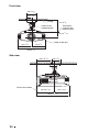
2 Position the projector so that the lens is parallel to the screen.
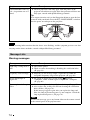
3 Project an image on the screen and adjust the picture so that it fits the
screen (1 page 19).
When using a screen with an uneven surface, stripes pattern may rarely appear on the screen
depending on the distance between the screen and the projector or the zooming magnifications. This
is not a malfunction of the projector.
Note
Screen
Top view

19
Connections and Preparations
Step 2: Adjusting the Picture Position
Project an image on the screen and then adjust the picture position.
Tip
The
?/1 (ON/STANDBY), INPUT, LENS, MENU, and M/m/</,/ (joystick) buttons on the
side panel of the projector function the same as those on the remote control.
Depending on the installation location of the projector, you may not control it with the remote
control. In this case, point the remote control to the screen instead of the projector.
Note
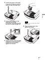
1 After connecting the AC cord to
the projector plug the AC cord
into a wall outlet.
The ON/STANDBY indicator lights
in red and the projector goes into
standby mode.
ON/STANDBY indicator
Remote control detector
3, 4, 5
Lens button
2
1
?/1 (On/
standby)
switch
Lights in red.

20
Be sure to adjust the picture size and the focus by using buttons on the remote control or the control
panel of the projector. Never make adjustments by directly turning the lens with your hands, which
may cause damage or malfunction to the projector.
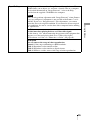
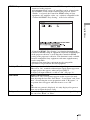
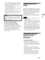
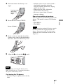
2 Press the ?/1 (ON/STANDBY)
switch to turn on the projector.
The lens protector will open.
The ON/STANDBY indicator flashes
in green, and then lights in green.
When the ON/STANDBY indicator
flashes, “Starting...” appears on the
screen.
3 Adjust the focus.
Press the LENS button repeatedly
until the Lens Focus adjustment
window (test pattern) appears. Then
adjust the focus of the picture by
pressing the M/m/</, buttons.
Each time you press the LENS button,
the LENS adjustment window appears
in order.
Tip
• When “Lens Control” is set to “Off” on
the Installation menu, you cannot
adjust the picture size and the focus (1
page 64).
When “Test Pattern” is set to “Off” on
the Function menu, the test pattern is
not displayed (1 page 63).
• The test signal is displayed for 1 minute.
Press the button to clear the test
signal display before that.
Note
Flashes in green fo
r
a while (tens of
seconds) and then
lights in green.
Page is loading ...
Page is loading ...
Page is loading ...
Page is loading ...
Page is loading ...
Page is loading ...
Page is loading ...
Page is loading ...
Page is loading ...
Page is loading ...
Page is loading ...
Page is loading ...
Page is loading ...
Page is loading ...
Page is loading ...
Page is loading ...
Page is loading ...
Page is loading ...
Page is loading ...
Page is loading ...
Page is loading ...
Page is loading ...
Page is loading ...
Page is loading ...
Page is loading ...
Page is loading ...
Page is loading ...
Page is loading ...
Page is loading ...
Page is loading ...
Page is loading ...
Page is loading ...
Page is loading ...
Page is loading ...
Page is loading ...
Page is loading ...
Page is loading ...
Page is loading ...
Page is loading ...
Page is loading ...
Page is loading ...
Page is loading ...
Page is loading ...
Page is loading ...
Page is loading ...
Page is loading ...
Page is loading ...
Page is loading ...
Page is loading ...
Page is loading ...
Page is loading ...
Page is loading ...
Page is loading ...
Page is loading ...
Page is loading ...
Page is loading ...
Page is loading ...
Page is loading ...
Page is loading ...
Page is loading ...
Page is loading ...
Page is loading ...
Page is loading ...
Page is loading ...
Page is loading ...
Page is loading ...
Page is loading ...
Page is loading ...
Page is loading ...
Page is loading ...
Page is loading ...
Page is loading ...
Page is loading ...
Page is loading ...
Page is loading ...
Page is loading ...
Page is loading ...
Page is loading ...
Page is loading ...
Page is loading ...
-
 1
1
-
 2
2
-
 3
3
-
 4
4
-
 5
5
-
 6
6
-
 7
7
-
 8
8
-
 9
9
-
 10
10
-
 11
11
-
 12
12
-
 13
13
-
 14
14
-
 15
15
-
 16
16
-
 17
17
-
 18
18
-
 19
19
-
 20
20
-
 21
21
-
 22
22
-
 23
23
-
 24
24
-
 25
25
-
 26
26
-
 27
27
-
 28
28
-
 29
29
-
 30
30
-
 31
31
-
 32
32
-
 33
33
-
 34
34
-
 35
35
-
 36
36
-
 37
37
-
 38
38
-
 39
39
-
 40
40
-
 41
41
-
 42
42
-
 43
43
-
 44
44
-
 45
45
-
 46
46
-
 47
47
-
 48
48
-
 49
49
-
 50
50
-
 51
51
-
 52
52
-
 53
53
-
 54
54
-
 55
55
-
 56
56
-
 57
57
-
 58
58
-
 59
59
-
 60
60
-
 61
61
-
 62
62
-
 63
63
-
 64
64
-
 65
65
-
 66
66
-
 67
67
-
 68
68
-
 69
69
-
 70
70
-
 71
71
-
 72
72
-
 73
73
-
 74
74
-
 75
75
-
 76
76
-
 77
77
-
 78
78
-
 79
79
-
 80
80
-
 81
81
-
 82
82
-
 83
83
-
 84
84
-
 85
85
-
 86
86
-
 87
87
-
 88
88
-
 89
89
-
 90
90
-
 91
91
-
 92
92
-
 93
93
-
 94
94
-
 95
95
-
 96
96
-
 97
97
-
 98
98
-
 99
99
-
 100
100


Sony VPL-VW90ES User manual
- Category
- Data projectors
- Type
- User manual
- This manual is also suitable for
Ask a question and I''ll find the answer in the document
Finding information in a document is now easier with AI
Related papers
-
Sony BRAVIA VPL-VW40 User manual
-
Sony VPL-VW60 User manual
-
Sony PK-R1FL User manual
-
Sony VPL-VW85 Operating instructions
-
Sony VPL-HW55ES Operating instructions
-
Sony VPL-HW40ES Operating Instructions Manual
-
-
Sony Projector VPL-VW600ES User manual
-
-
Sony VPL-HW65 Operating instructions
Other documents
-
Harbor Freight Tools Watch Case Press with Nylon Dies User manual
-
Power Acoustik PT-151CM Owner's manual
-
Panasonic PT-AE4000U User manual
-
LG AF115 Important information
-
Hisense LHD32K370WTEU Owner's manual
-
Anker D4111111 User manual
-
 SENSTAR BR100 User guide
-
Panasonic PT-AX User manual
-
 Mitsubishi Electronics HC7000 User manual

