Page is loading ...

Manufacturer reserves the right to discontinue, or change at any time, specifications or designs without notice and without incurring obligations.
Catalog No. 04-53190012-01 Printed in U.S.A. Form 19XRV-3SS Pg 1 711 3-11 Replaces: New
Start-Up and Service Instructions
SAFETY CONSIDERATIONS
Centrifugal liquid chillers are designed to provide safe and
reliable service when operated within design specifica-
tions. When operating this equipment, use good judgment
and safety precautions to avoid damage to equipment and
property or injury to personnel.
Be sure you understand and follow the procedures and
safety precautions contained in the chiller instructions as
well as those listed in this guide.
ONLY QUALIFIED Electrical Personnel familiar with the construction
and operation of this equipment and the hazards involved should install,
adjust, operate, or service this equipment.
READ AND UNDERSTAND this manual and other applicable manuals in
their entirety before proceeding. Failure to observe this precaution could
result in severe bodily injury or loss of life.
DO NOT install modification kits with power applied to the drive. Discon-
nect and lock out incoming power before attempting such installation or
removal. Failure to observe this precaution could result in severe bodily
injury or loss of life
UNUSED WIRES in conduit must be grounded at both ends to avoid a
possible shock hazard caused by induced voltages. Also, if a drive sharing
a conduit is being serviced or installed; all drives using this conduit should
be disabled to eliminate the possible shock hazard from cross-coupled
motor leads. Failure to observe these precautions could result in bodily
injury.
DO NOT VENT refrigerant relief valves within a building. Outlet from
rupture disc or relief valve must be vented outdoors in accordance with the
latest edition of ANSI/ASHRAE 15 (American National Standards Insti-
tute/American Society of Heating, Refrigerating, and Air Conditioning
Engineers). The accumulation of refrigerant in an enclosed space can dis-
place oxygen and cause asphyxiation.
PROVIDE adequate ventilation in accordance with ANSI/ASHRAE 15,
especially for enclosed and low overhead spaces. Inhalation of high con-
centrations of vapor is harmful and may cause heart irregularities, uncon-
sciousness, or death. Misuse can be fatal. Vapor is heavier than air and
reduces the amount of oxygen available for breathing. Product causes eye
and skin irritation. Decomposition products are hazardous.
DO NOT USE OXYGEN to purge lines or to pressurize a chiller for any
purpose. Oxygen gas reacts violently with oil, grease, and other common
substances.
NEVER EXCEED specified test pressures, VERIFY the allowable test
pressure by checking the instruction literature and the design pressures on
the equipment nameplate.
DO NOT USE air for leak testing. Use only refrigerant or dry nitrogen.
DO NOT VALVE OFF any safety device.
BE SURE that all pressure relief devices are properly installed and func-
tioning before operating any chiller.
THERE IS A RISK OF INJURY OR DEATH by electrocution. High volt-
age may be present on the motor leads even though the motor is not run-
ning. Open the power supply disconnect before touching motor leads or
terminals.
DO NOT WELD OR FLAMECUT any refrigerant line or vessel until all
refrigerant (liquid and vapor) has been removed from chiller. Traces of
vapor should be displaced with dry air or nitrogen and the work area
should be well ventilated. Refrigerant in contact with an open flame pro-
duces toxic gases.
DO NOT work on high-voltage equipment unless you are a qualified elec-
trician.
DO NOT WORK ON electrical components, including control panels,
switches, VFD, or oil heater until you are sure ALL POWER IS OFF and
no residual voltage can leak from capacitors or solid-state components.
LOCK OPEN AND TAG electrical circuits during servicing. IF WORK IS
INTERRUPTED, confirm that all circuits are deenergized before resuming
work.
AVOID SPILLING liquid refrigerant on skin or getting it into the eyes.
USE SAFETY GOGGLES. Wash any spills from the skin with soap and
water. If liquid refrigerant enters the eyes, IMMEDIATELY FLUSH EYES
with water and consult a physician.
DO NOT ATTEMPT TO REMOVE fittings, covers, etc., while chiller is
under pressure or while chiller is running. Be sure pressure is at 0 psig (0
kPa) before breaking any refrigerant connection.
TO AVOID an electric shock hazard, verify that the voltage on the bus
capacitors has discharged completely before servicing. Check the DC bus
voltage at the Power Terminal Block by measuring between the +DC and -
DC terminals, between the +DC terminal and the chassis, and between the
-DC terminal and the chassis. The voltage must be zero for all three mea-
surements.
THE USER is responsible to conform with all applicable local, national,
and international codes. Failure to observe this precaution could result in
damage to, or destruction of, the equipment.
THIS DRIVE contains ESD (Electrostatic Discharge) sensitive parts and
assemblies. Static control precautions are required when installing, testing,
servicing or repairing this assembly. Component damage may result if
ESD control procedures are not followed. For static control procedures,
reference Rockwell publication Guarding Against Electrostatic Damage, or
any other applicable ESD protection handbook.
DO NOT alter the setting of any jumper. Failure to observe this precaution
could result in damage to, or destruction of, the equipment.
USE OF power correction capacitors on the output of the drive can result
in erratic operation of the motor, nuisance tripping, and/or permanent dam-
age to the drive. Remove power correction capacitors before proceeding.
Failure to observe this precaution could result in damage to, or destruction
of, the equipment.
MOST CODES require that upstream branch circuit protection be pro-
vided to protect input power wiring. If fuses are chosen as the protection
method, refer to the PowerFlex 750 user manual. Failure to observe this
precaution could result in damage to, or destruction of, the equipment.
DO NOT route signal and control wiring with power wiring in the same
conduit. This can cause interference with drive operation. Failure to
observe this precaution could result in damage to, or destruction of, the
equipment.
DISTRIBUTION SYSTEM short circuit capacity shall not exceed the rat-
ing of the drive. Failure to observe this precaution could result in damage
to, or destruction of, the equipment.
DO NOT STEP on refrigerant lines. Broken lines can whip about and
release refrigerant, causing personal injury.
DO NOT climb over a chiller. Use platform, catwalk, or staging. Follow
safe practices when using ladders.
USE MECHANICAL EQUIPMENT (crane, hoist, etc.) to lift or move
inspection covers or other heavy components. Even if components are
light, use mechanical equipment when there is a risk of slipping or losing
your balance.
BE AWARE that certain automatic start arrangements CAN ENGAGE
THE VFD, TOWER FAN, OR PUMPS. Open the disconnect ahead of the
VFD, tower fans, or pumps.
USE only repair or replacement parts that meet the code requirements of
the original equipment.
PERIODICALLY INSPECT all valves, fittings, and piping for corrosion,
rust, leaks, or damage.
DANGER
WARNING
CAUTION
19XRV
with PIC III Controls
Rockwell PowerFlex 755 VFD Option

2
CONTENTS
Page
SAFETY CONSIDERATIONS . . . . . . . . . . . . . . . . . . . . . . 1
INTRODUCTION . . . . . . . . . . . . . . . . . . . . . . . . . . . . . . . . . . 2
ABBREVIATIONS AND EXPLANATIONS . . . . . . . . . . 2
Required Publications. . . . . . . . . . . . . . . . . . . . . . . . . . . . 2
Getting Assistance from Rockwell Automation . . . 2
IDENTIFYING DRIVE COMPONENTS. . . . . . . . . . . . 2-5
Opening the VFD Access Door . . . . . . . . . . . . . . . . . . . 3
Drive Assembly Catalog Number . . . . . . . . . . . . . . . . . 3
Components and Physical Data . . . . . . . . . . . . . . . . . . 3
START-UP . . . . . . . . . . . . . . . . . . . . . . . . . . . . . . . . . . . . . . 5-8
Alternate Wire Lugs . . . . . . . . . . . . . . . . . . . . . . . . . . . . . . 5
Verify Installation. . . . . . . . . . . . . . . . . . . . . . . . . . . . . . . . . 5
Configure the VFD. . . . . . . . . . . . . . . . . . . . . . . . . . . . . . . . 6
Commissioning the Unit. . . . . . . . . . . . . . . . . . . . . . . . . . 6
Check Internal Jumpers . . . . . . . . . . . . . . . . . . . . . . . . . . 7
SERVICE . . . . . . . . . . . . . . . . . . . . . . . . . . . . . . . . . . . . . . 8-27
Troubleshooting the Drive . . . . . . . . . . . . . . . . . . . . . . . . 8
• ICVC ALERT CODES
• ICVC ALARM CODES
• TEST EQUIPMENT NEEDED TO TROUBLESHOOT
• VERIFYING THAT DC BUS CAPACITORS ARE
DISCHARGED
• HIGH TEMPERATURE ALARMS
• MAIN CONTROL BOARD (MCB) COMPONENTS
Checking Power Modules and Motor Input
with Input Power Off . . . . . . . . . . . . . . . . . . . . . . . . . . 22
Servicing the Drive . . . . . . . . . . . . . . . . . . . . . . . . . . . . . . 23
• REMOVING THE DRIVE
• RIGGING THE ENCLOSURE
• REPLACING THE GATEWAY (A-B20-750-20COMM
OPTION CARD)
• CHILL PLATE FAN AND INTERNAL FAN
REPLACEMENT
Parts Identification and Location . . . . . . . . . . . . . . . . 26
APPENDIX A — WIRING SCHEMATICS . . . . . . . 28-31
APPENDIX B — OPTIONAL BACNET
COMMUNICATIONS WIRING . . . . . . . . . . . . . . . 32-38
INTRODUCTION
The Carrier VFD option Start-Up and Service Manual is in-
tended for trained and qualified service personnel, and is to be
used during start up, operation, and maintenance of Rockwell/
Allen-Bradley PF755L drive.
ABBREVIATIONS AND EXPLANATIONS
Frequently used abbreviations in this manual include:
Required Publications — The Carrier VFD option
Start-Up and Service Manual must be used with the following
manuals:
• The latest version of the PowerFlex 750-Series AC
Drives manuals
• The latest revision of the Start-Up, Operation, and Main-
tenance Instructions for the 19XRV with PIC III Controls
Getting Assistance from Rockwell Automa-
tion — Contact the local Rockwell Automation sales office
with any questions or problems relating to the products de-
scribed in this manual. For technical support on drives between
the hours of 7:00 am and 6:00 pm CST, M-F, call 1-262-512-
8176. For information about after-hours phone support and on-
site support call 1-800-800-0522.
Before calling, have the following information available
from the Allen-Bradley data nameplate located inside the en-
closure on the right wall. See Fig. 1.
• Allen-Bradley ID or CAT. NO.
• Carrier VFD Code
• Allen-Bradley serial number
IDENTIFYING DRIVE COMPONENTS
A chiller control schematic and a VFD schematic are in-
cluded in Appendix A.
CCM — Chiller Control Module
DC — Direct Current
DPI — Drive Peripheral Interface
ENET — Ethernet
ICVC — International Chiller Visual Controller
IGBT — Insulated Gate Bipolar Transistor
I/O — Inputs/Outputs
IP — Internet Protocol
IPWM — Inverter Pulse Width Modulation
MCB — Main Control Board
MOV — Metal Oxide Varistor
PE — Protective Earthing Conductor
SIO — Sensor Input/Output
STS — Status
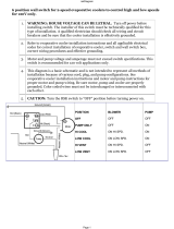
WARNING
DC bus capacitors retain hazardous voltages after input
power has been disconnected. After disconnecting input
power, wait five (5) minutes for the DC bus capacitors to
discharge and then check the voltage with a voltmeter rated
for the DC bus voltage to ensure the DC bus capacitors are
discharged before touching any internal components. Fail-
ure to observe this precaution could result in severe bodily
injury or loss of life.
An isolated multimeter will be needed to measure DC bus
voltage and to make resistance checks. The drive’s DC bus
capacitors retain hazardous voltages after input power has
been disconnected.
Fig. 1 — Allen Bradley Data Nameplate
A19-1830
711

3
Opening the VFD Access Door
1. Using recommended screwdriver = 6.4 mm (0.25 in.) flat
or T20 star, open access door. See Fig. 2.
2. Check to be sure that the voltage between DC+ and DC-
and from each DC terminal to the chassis is zero before
proceeding. See Fig. 3.
Drive Assembly Catalog Number — See Fig. 4 for
an example Catalog Number.
Components and Physical Data — The Allen-
Bradley PF755 Frame 6 drive is used for the 230-amp rated ap-
plication (carrier Part No. 19XRV0230...). See Fig. 5.
The Allen-Bradley PF755 Frame 7 drive is used for the
335-amp and 445-amp rated application (Carrier Part No.
19XVR0335... and 19XVR0445... respectively). See Fig. 6.
See Fig. 7 for the dimensions of Frames 6 and 7.
WARNING
Before removing the drive enclosure, open access door and
verify that the DC bus voltage has dropped to zero by
checking the terminals behind the access door. Failure to
observe this precaution could result in severe bodily injury
or loss of life.
Fig. 2 — Opening Access Door
A19-1831
1
L1 L2 L3
O
I
2
DC+ DC–
0V
0V
LOCKOUT/TAGOUT
MULTIMETER
DC BUS TEST
TERMINALS
LOCATED INSIDE
ACCESS DOOR
Fig. 3 — Check DC Bus Terminals
A19-1814
21P 1 0248 3 - 3 -0-0 C-
21P PF755 VFD
Voltage Rating
1
2
3
Customer
C –Carrier
Meter Package
0 – No Meter Package
1 –Analog Meter Package
– 460 to 480 v, 60 Hz
– 380 to 415 v, 50 Hz
– 380 to 400 v, 60 Hz
4
PF755 Full Load Amp Rating
(Maximum Continuous Amps)*
0248 – 248
0361 – 361
0477
477
Disconnect/Breaker Options
3
65 KAIC Capacity Breaker
Input Reactor
0 – No Input Reactor
1 – 3% Input Line Reactor
– 401 to 439 v, 60 Hz
0477
–
477
3
–
65
KAIC
Capacity
Breaker
4 – 100 KAIC Capacity Breaker
Drive Assembly
3 – Unit Mount NEMA 1 Liquid Cooled
Fig. 4 — Drive Assembly Catalog Number Nomenclature
A19-1842
* For Carrier applications, maximum continuous amp
ratings are 230, 335, and 445.

4
LEGEND
Fig. 5 — Frame 6 Drive Components
NO. NAME DESCRIPTION
1 Power Terminals R/L1, S/L2, T/L3, U/T1, V/T2, W/T3
2
PE Grounding Studs Terminating point to chassis ground
for incoming motor shield
3
DC Bus and Brake
Terminals
+DC, -DC, BR1, BR2
4 PE-A and PE-B MOV and CMC Jumper Wires
5 DC+ and DC- Bus Voltage Test Points
A19-
1832
LEGEND
Fig. 6 — Frame 7 Drive Components
NO. NAME DESCRIPTION
1 Power Terminals R/L1, S/L2, T/L3, U/T1, V/T2, W/T3
2
PE Grounding Studs Terminating point to chassis ground
for incoming motor shield
3
DC Bus and Brake
Te rm in al s
+DC, -DC, BR1, BR2
4 PE-A and PE-B MOV and CMC Jumper Wires
5 DC+ and DC- Bus Voltage Test Points
A19-1833

5
START-UP
Alternate Wire Lugs —
In the case where the incoming
power wire size does not fit the standard lug, alternate lugs may
be used. See Table 1. Note that lugs rated for a higher current
than the circuit breaker may be used.
Table 1 — Wire Lugs
Verify Installation — Record the following job
information:
1. Job Name
2. Job Number
3. City
4. State
5. Zip Code
Record the following nameplate information:
1. From the Allen-Bradley nameplate (Fig. 1) located inside
the VFD enclosure:
a. Allen-Bradley ID or CAT NO.
b. Allen-Bradley Serial Number
c. Carrier Part Number
2. From the machine nameplete (Fig. 8) located inside the
VFD enclosure:
a. Chiller Serial Number
b. Chiller Model
c. Motor rated load amps
d. Motor nameplate rpm
e. Motor nameplate kW
f. Motor nameplate voltage
g. IPWM (pulse width modulation) frequency
h. Voltage
3. From the drive module label (Fig. 9) located on the drive
module:
a. Model or Cat. Number
b. Serial Number
4. From the ICVC control panel screen:
a. Carrier Part Number and Revision
b. ICVC Software Number
Rockwell PowerFlex 750 drive start-up must be registered
on the Rockwell website. Rockwell Registration site URL:
http://www.automation.rockwell.com/warp/default.asp
DANGER
Internal components and circuit boards of the drive are live
when the drive is connected to incoming power. Coming
into contact with this voltage is extremely dangerous and
will result in severe personal injury or death.
The motor terminals U, V, W and the DC-link/brake resis-
tor terminals B+/R+, R- are live when the drive is con-
nected to incoming power, even if the motor is not running.
Do not make any connections when the drive is connected
to the incoming power.
After having disconnected the drive, wait until the indica-
tors on the keypad go out (if no keypad is attached see the
indicator through the keypad base). Wait 5 more minutes
before doing any work on drive connections. Do not even
open the cover before this time has expired..
Before connecting the drive to the incoming power, make
sure that the switchgear enclosure door is closed.
WARNING
The control I/O-terminals are isolated from the mains
potential. However, the relay outputs and other I/O termi-
nals may have a dangerous control voltage present even
when the drive is disconnected from incoming power.
Coming into contact with this voltage could result in severe
personal injury.
Fig. 7 — Enclosure Dimensions - Frames 6 and 7
A19-1834
CAUTION
If other than refrigerant cooling is used, before connecting
the drive to the incoming power, make sure that the coolant
is circulating and has no leaks.
CAUTION
When working with the Drive Explorer, never use the
Rotate function as the motor will immediately start and
severe compressor damage could result.
CIRCUIT
BREAKER
STANDARD
ABB LUG
STANDARD
LUG CABLE
RANGE
ALTERNATE
ABB LUG
ALTERNATE
LUG CABLE
RANGE
65 KAIC
(Standard)
K6TJ
(3) 2/0 - 400
MCM
K6TH
(2) 250 - 500
MCM
100 KAIC
(Optional)

6
Configure the VFD — All configurations required by
the VFD are supplied by the ICVC through the VFD Gateway.
Any configuration changes necessary and possible are made on
the ICVC screens. A complete set of configurations is transmit-
ted to the VFD each time the controls are powered up.
The following is from the 19XRV PIC III ICVC screen. Pa-
rameters in italics are to be entered or confirmed at start-up. Pa-
rameters in bold are to be changed only after consulting with
Carrier service engineering. See Table 2.
Table 2
— VFD Configurations
* Parameters marked with an * are not downloadable to the VFD but are used
in other calculations and algorithms in the ICVC.
NOTES:
1. Parameters in italics are to be entered or confirmed at start-up.
2. Parameters in bold are to be changed only after consultation with ser-
vice engineering.
Commissioning the Unit — The commission proce-
dure is as follows:
1. If the chiller has been stored outdoors, allow at least 24
hours room temperature stabilization prior to commis-
sioning. Ensure any condensation that occurs as a result
of the ambient temperature is allowed to evaporate.
2. Enter parameters in the VFD_CONF screen.
3. Install surge suppression devices if required.
4. Review the power wiring and grounding to ensure that it
has been properly connected.
5. Visually examine the inside of the drive enclosure to:
a. Look for signs of corrosion or moisture residue.
b. Remove any dirt or debris.
c. Make sure all vents are clear.
6. Apply power to the drive and take thermal measurements
of the capacitor bank and power connections. Do this
again before start-up.
7. Measure and record the incoming line voltage. Line-to-
line voltages should be balanced within 3% as calculated
by Rockwell’s procedure below:
Measure voltages phase-to-phase and phase-to-ground.
MODEL NUMBER
SERIAL NUMBER
VOLTS/PHASE/HERTZ
LOCKED ROTOR AMPS
OVERLOAD TRIP AMPS
MAX FUSE/CIRCUIT BREAKER SIZE
MIN SUPPLY CIRCUIT AMPACITY
MOTOR NAMEPLATE VOLTAGE
COMPRESSOR 100% SPEED
RATED LINE VOLTAGE
RATED LINE AMPS
RATED LINE KILOWATTS
MOTOR RATED LOAD KW
MOTOR RATED LOAD AMPS
MOTOR NAMEPLATE AMPS
MOTOR NAMEPLATE RPM
MOTOR NAMEPLATE KW
INTERTER PWM FREQUENCY
MACHINE NAMEPLATE SUPPLY DATA
MACHINE ELECTRICAL DATA
SAFETY CODE CERTIFICATION
THE COMPRESSOR MOTOR CONTROLLER AND OVERLOAD PROTECTION MUST BE
IN ACCORDANCE WITH CARRIER SPECIFICATION Z-420.
19XV05008701 REV. 3
A United Technologies Company
Fig. 8 — Machine Nameplate
a19-
1846
Fig. 9 — Drive Module Label
a19-
1924
PARAMETER DEFAULT VALUE
Motor Nameplate Voltage 460
Compressor 100% Speed
Line Freq=60 Hz? (No=50) Yes
Rated Line Voltage* 460
Rated Line Amps* 200
Rated Line Kilowatts * 100
Motor Rated Load kW* 100
Motor Rated Load Amps* 200
Motor Nameplate Amps 100
Motor Nameplate RPM 3456
Motor Nameplate KW 100
Inverter PWM Frequency (0 = 4 kHz, 1 =
2kHz)
1
Skip Frequency 1 (Hz) 102.0
Skip Frequency 2 (Hz) 102.0
Skip Frequency 3 (Hz) 102.0
Skip Frequency Band Line (Hz) 0.0
Voltage % Imbalance 10
Line Volt Imbalance Time (sec) 10
Line Current % Imbalance 40
Line Current Imbal Time (sec) 10
Motor Current % Imbalance 40
Motor Current Imbal Time 10
Increase Ramp Time (sec) 30
Decrease Ramp Time (sec) 30
Single Cycle Dropout (DSABLE/ENABLE) DSABLE

7
Vmax = Maximum measured phase-to-phase voltage
(A to B, B to C, C to A)
Vmin = Minimum measured phase-to-phase voltage
Imbalance Calculation Formula
8. Take a final thermal measurement of the capacitor bank
and power after finalizing the installation to ensure all
connections are good.
9. If a ground fault occurs, then do the following:
a. Check for a ground in the motor or motor wiring.
b. Check for damage to wiring insulation and that
wiring is dry.
c. Verify the motor wiring is separated from ground
and there is no connection between phases.
d. Check for failed IGBTs.
10. If an Overcurrent fault occurs, then do the following:
a. Check for excessive load and verify load limit set-
tings on the ICVC.
b. Check motor and wiring insulation.
c. Check parameter settings on VFD_CONF screen
in the ICVC.
Check Internal Jumpers — On the Main VFD Con-
trol board there are two jumpers labeled J1 HARDWARE EN-
ABLE and J2 SAFETY ENABLE. J1 should be removed and
J2 should be in place. See Fig. 10.
There are two jumper wires that connect a particular termi-
nal to chassis ground. The MOV and AC EMI jumper should
be connected to the PE-A terminal. The COMMON MODE
CAPACITORS to GROUND jumper should be connected to a
standoff rather than the PE-B terminal.
Use the recommended tools as follows when connecting
jumper wires in Frame 6 and in Frame 7:
• Recommended torque (screws and nuts) = 1.36 N·m
(120.0 lb·in)
• Recommended hex socket = 7 mm
• Recommended screwdriver = T20 star type
See Fig. 11A and Fig. 11B for the correct positions of the
jumpers.
Va v g =
(VAB + VBC + VCA)
3
Imbalance % =
(Vmax – Vmin) x 100
Va vg
LEGEND
NO. NAME DESCRIPTION
1 HIM Connector DPI Port 1 (HIM Cradle) connection.
2
Fan Connector Power supply for internal cooling fan
(Frames 2 & 3).
3
Battery
Receptacle
User installed CR1220 lithium coin cell
battery provides power to the Real Time
Clock (Optional, not supplied).
4
DPI Port 2 Cable connection for handheld and
remote HIM options.
5
Embedded EtherNet/
IP Address Selectors
Rotary switches for setting lowest octet
of EtherNet address (forces address to
192.168.1.xxx).
6
Embedded EtherNet/
IP Connector
Network cable connection.
7
Jumper J2 SAFETY Safety enable jumper. Removed when
safety option is installed.
8
Jumper J1 ENABLE Hardware enable jumper. Removed
when a hardware enable configuration is
utilized.
9 TB1 I/O terminal block.
Fig. 10 — PF755 Main Control Board
TB1 I/O Terminal Designations
FIXED I/O TERMINAL NAME DESCRIPTION
Di 0ac
Digital Input 120V AC Connections for AC power supply.
Di C
Digital Input Common Digital input common
Di 0dc
Digital Input 24V DC Connections for DC power supply.
+24V
+24 Volt Power Connections for drive supplied 24V power.
24VC
24 Volt Common
IMPORTANT: Wiring to pluggable terminal block connectors
should be supported by wire ties or other means to help pre-
vent unintentional disconnection
Di 0ac
Di C
Di 0dc
+24V
24VC
a19-1921

8
SERVICE
Troubleshooting the Drive —
The drive can display
two kinds of error codes on the ICVC called the Alert and
Alarm codes. These codes signal a problem detected during
self tuning or drive operation. Alert and Alarm codes are locat-
ed in the 19XRV Start-Up, Operation and Maintenance Instruc-
tions. Note the following differences between Carrier and
Allen-Bradley terminology:
• A warning message on the ICVC is an ALERT.
• The same warning viewed with Rockwell Drive Explorer
is a VFD ALARM.
• A failure resulting in a shutdown is seen as an ALARM
on the ICVC and as a VFD FAULT when viewed with
Drive Explorer.
CONDITION CODES
ICVC ALERT = VFD ALARM
ICVC ALARM = VFD FAULT
See Tables 3-6 and Fig. 12.
ICVC ALERT CODES — An alert condition is indicated by
a message at the top of the ICVC default screen. In addition, an
exclamation point (!) will appear next to any affected point on
an ICVC display screen. The drive will continue to operate
during the alert condition. Investigate the cause of the alert to
ensure it does not lead to a fault condition. The alert code will
automatically be cleared from the ICVC when the condition
causing the alert no longer exists. See Table 4.
ICVC ALARM CODES — An alarm condition is also indi-
cated by a message at the top of the ICVC default screen. If an
alarm occurs, the drive coasts to stop. The STS (status) light on
the drive will turn from Green to Red or Yellow (see Table 3).
The detected fault message is maintained on the display until it
is cleared by pressing the RESET softkey. See Table 5.
TEST EQUIPMENT NEEDED TO TROUBLESHOOT —
An isolated multimeter adequately rated for the DC bus volt-
age will be needed to measure DC bus voltage and to make
resistance checks. Note that dedicated troubleshooting test
points are not provided.
WARNING
DC bus capacitors retain hazardous voltages after input
power has been disconnected. After disconnecting input
power, wait five (5) minutes for the DC bus capacitors to
discharge and then check the voltage with a voltmeter to
ensure the DC bus capacitors are discharged before touch-
ing any internal components. Failure to observe this pre-
caution could result in severe bodily injury or loss of life.
Fig. 11A — Jumper Wire Locations — Frame 6
A19-1835
Fig. 11B — Jumper Wire Locations — Frame 7
A19-1836
2
8
5
79
13
46
Allen-Bradley
Fig. 12 — Drive Status Indicator
A1
9-
1815

9
Table 3
— Drive Status Indicator Descriptions
NOTES:
1. A Type 1 alarm indicates that a condition exists. Type 1 alarms
are user configurable.
2. A Type 2 alarm indicates that a configuration error exists and
the drive cannot be started. Type 2 alarms are not configurable.
VERIFYING THAT DC BUS CAPACITORS ARE DIS-
CHARGED — The drive’s DC bus capacitors retain hazard-
ous voltages after input power has been disconnected. Perform
the following steps before touching any internal components:
1. Turn off and lock out input power. Wait five minutes.
2. Verify that there is no voltage at the drive’s input power
terminals.
3. Measure the DC bus potential with a voltmeter while
standing on a non-conductive surface and wearing insu-
lated gloves (1000 V). Measure the DC bus potential. See
Fig. 5 for the 248-amp drive and Fig. 6 for the 361 and
477-amp drives. The voltage between DC+ and DC-, and
from each DC terminal to the chassis must be zero before
proceeding.
4. Once the drive has been serviced, reapply input power.
HIGH TEMPERATURE ALARMS — Coolant flow
through the cold plate is controlled by an orifice in the refriger-
ant line leaving the cold plate. The orifice looks like one of the
O-ring face seal connectors and in fact is used as one of the
connections on the coolant tubing. The difference is that the
passage through the fitting is 0.375 in. (9.5 mm). If the orifice
is present and condenser liquid flow is present, the liquid will
flash to cooler temperature at the orifice. This temperature dif-
ference is great enough to be easily felt.
MAIN CONTROL BOARD (MCB) COMPONENTS —
Figure 13 shows the drive module with the cover removed. To
access the control boards, loosen the screw on the face of the
keypad mount and swing the keypad mount upward.
The components on the main control board (MCB) are
shown in Fig. 14. Note the location of the terminals labeled
MCB I/O. The high pressure switch is wired to these terminals
as shown in Fig. 15. In the event of a high condenser pressure
alarm, the connections at these terminals should be checked
and tightened if necessary.
A typical wiring schematic is shown in Appendix A.
NAME COLOR STATE DESCRIPTION
STS (Status)
Green Flashing Drive ready but not running, and no faults are present.
Steady Drive running, no faults are present.
Yellow Flashing Drive is not running. A type 2 (non-configurable) alarm condition exists and the
drive cannot be started.
Steady Drive is not running, a type 1 alarm condition exists. The drive can be started.
Red Flashing A major fault has occurred. Drive cannot be started until fault condition is
cleared.
Steady A non-resettable fault has occurred.
Red/Yellow Flashing Alternately A minor fault has occurred. When running, the drive continues to run. System is
brought to a stop under system control. Fault must be cleared to continue. Use
parameter 950 [Minor Flt Config] to enable. If not enabled, acts like a major
fault.
Green/Red Flashing Alternately Drive is flash updating.
ENET
None (Unlit) Off Adapter and/or network is not powered, adapter is not properly connected to
the network, or adapter needs an IP address.
Red Flashing An EtherNet/IP connection has timed out.
Steady Adapter failed the duplicate IP address detection test.
Red/Green Flashing Alternately Adapter is performing a self-test.
Green Flashing Adapter is properly connected but is not communicating with any devices on
the network.
Steady Adapter is properly connected and communicating on the network.
LINK
None (Unlit) Off Adapter is not powered or is not transmitting on the network.
Green Flashing Adapter is properly connected and transmitting data packets on the network.
Steady Adapter is properly connected but is not transmitting on the network.
SWING UP KEY PAD
MOUNT TO ACCESS
CONTROL BOARDS
Fig. 13 — Drive Module with Cover Removed
a19-1843

10
DPI PORT 02 (COMPUTER PORT)
DIGITAL INPUT TERMINAL BLOCKS
(SLOTS 04 & 05)
ETHERNET/IP ADDRESS SWITCHES
DIGITAL OUTPUT TERMINAL BLOCKS
(SLOTS 04 & 05)
EMBEDDED ETHERNET/IP PORT
MCB I/O TERMINALS
(AUX FAULT /
HIGH PRESSURE FAULT /
ENABLE INPUT)
Fig. 14 — MCB (Main Control Board) Components
a19-1844
*Located outside of starter; connected by field wiring.
Fig. 15 — High Pressure Switch Wiring
a19-1925

11
Table 4 — ICVC Alert Codes
PRE-START ALERTS: These alerts only delay start-up. When alert is corrected, the start-up will continue. No reset is
necessary.
*[LIMIT] is shown on the ICVC as temperature, pressure, voltage, etc., predefined or selected by the operator as an override or an alert. [VALUE] is
the actual pressure, temperature, voltage, etc., at which the control tripped.
ICVC FAULT
STATE
PRIMARY
MESSAGE
SECONDARY
MESSAGE
PRIMARY CAUSE ADDITIONAL CAUSE/REMEDY
100 PRESTART
ALERT
STARTS LIMIT
EXCEEDED
100Excessive compressor starts
(8 in 12 hours).
Depress the RESET softkey if additional start
is required. Reassess start-up requirements.
101 PRESTART
ALERT
HIGH BEARING
TEMPERATURE
101Comp Thrust Brg Temp [VALUE]
exceeded limit of [LIMIT]*.
Check oil heater for proper operation.
Check for low oil level, partially closed oil sup-
ply valves, clogged oil filters.
Check the sensor wiring and accuracy.
Check Comp Thrust Brg Alert setting in
SETUP1 screen.
102 PRESTART
ALERT
HIGH MOTOR
TEMPERATURE
102Comp Motor Winding Temp
[VALUE] exceeded limit of [LIMIT]*.
Check motor sensors for wiring and accuracy.
Check motor cooling line for proper operation,
or restrictions.
Check for excessive starts within a short time
span.
Check Comp Motor Temperature Override
setting in SETUP1 screen.
103 PRESTART
ALERT
HIGH
DISCHARGE
TEMP
103Comp Discharge Temp [VALUE]
exceeded limit of [LIMIT]*.
Allow discharge sensor to cool.
Check sensor wiring and accuracy.
Check for excessive starts.
Check Comp Discharge Alert setting in
SETUP1 screen.
104 PRESTART
ALERT
LOW
REFRIGERANT
TEMP
104Evaporator Refrig Temp [VALUE]
exceeded limit of [LIMIT]*.
Check transducer wiring and accuracy.
Check for low chilled fluid supply
temperatures.
Check refrigerant charge.
Check Refrig Override Delta T in SETUP1
screen.
105 PRESTART
ALERT
LOW OIL
TEMPERATURE
105Oil Sump Temp [VALUE]
exceeded limit of [LIMIT]*.
Check oil heater contactor/relay and power.
Check oil level and oil pump operation.
106 PRESTART
ALERT
HIGH
CONDENSER
PRESSURE
106Condenser Pressure [VALUE]
exceeded limit of [LIMIT]*.
Check transducer wiring and accuracy.
Check for high condenser water
temperatures.
Check high condenser pressure switch wiring.
107 PRESTART
ALERT
LOW LINE
VOLTAGE
107Percent Line Voltage [VALUE]
exceeded limit of [LIMIT]*.
Check voltage supply.
Check voltage transformers and switch gear.
Consult power utility if voltage is low.
108 PRESTART
ALERT
HIGH LINE
VOLTAGE
108Percent Line Voltage [VALUE]
exceeded limit of [LIMIT]*.
Check voltage supply.
Check power transformers.
Consult power utility if voltage is high.
109 PRESTART
ALERT
GUIDE VANE
CALIBRATION
109Actual Guide Vane Pos
Calibration Required Before Startup.
Press STOP button on ICVC and perform
Guide Vane Calibration in Controls Test
screen.
Check guide vane actuator feedback
potentiometer.
110 PRESTART
ALERT
HIGH
RECTIFIER
TEMP
110Rectifier Temperature [VALUE]
exceeded limit of [LIMIT]*.
Check that VFD refrigerant isolation valves
are open.
Check VFD refrigerant cooling solenoid and
refrigerant strainer.
Check for proper VFD cooling fan operation
and blockage.
111 PRESTART
ALERT
HIGH
INVERTER
TEMP
111Inverter Temperature [VALUE]
exceeded limit of [LIMIT]*.
Check that VFD refrigerant isolation valves
are open.
Check VFD refrigerant cooling solenoid and
refrigerant strainer.
Check for proper VFD cooling fan operation
and blockage.

12
Table 4 — ICVC Alert Codes (cont)
NORMAL RUN WITH OVERRIDES
*[LIMIT] is shown on the ICVC as the temperature, pressure, voltage, etc., set point predefined or selected by the operator as an override, alert, or
alarm condition. [VALUE] is the actual pressure, temperature, voltage, etc., at which the control tripped.
ICVC FAULT
STATE
PRIMARY
MESSAGE
SECONDARY
MESSAGE
PRIMARY CAUSE ADDITIONAL CAUSE/REMEDY
120 RUN CAPACITY
LIMITED
HIGH CONDENSER
PRESSURE
120Condenser Pressure
[VALUE] exceeded limit of
[LIMIT]*.
Check condenser water pump operation.
Check for high condenser water temperatures or
low flow rate. Verify that isolation valves are
open.
Check Cond Press Override setting in SETUP1.
121 RUN CAPACITY
LIMITED
HIGH MOTOR
TEMPERATURE
121Comp Motor Winding
Temp [VALUE] exceeded
limit of [LIMIT]*.
Check for closed valves or restriction in motor
cooling lines.
Check for closed refrigerant isolation valves.
Check Comp Motor Temp Override setting in
SETUP1.
122 RUN CAPACITY
LIMITED
LOW EVAP REFRIG
TEMP
122Evaporator Refrig
Temp [VALUE] exceeded
limit of [LIMIT]*.
Check refrigerant charge.
Check that optional cooler liquid line isolation
valve is fully open.
Check for excessive condenser flow or low
chilled water flow.
Check for low entering cooler temperature.
Check that condenser inlet and outlet water
nozzles are piped correctly.
Check for waterbox division plate gasket bypass.
123 RUN CAPACITY
LIMITED
HIGH COMPRESSOR
LIFT
123Surge Prevention
Override: Lift Too High For
Compressor
Check for high condenser water temperature or
low suction temperature.
Check for high Evaporator or Condenser
approaches.
Check surge prevention parameters in
OPTIONS screen.
124 RUN CAPACITY
LIMITED
MANUAL GUIDE VANE
TA RG E T
124Run Capacity Limited:
Manual Guide Vane Target.
Target Guide Vane Position has been forced in
the COMPRESS screen. Select and RELEASE
force to return to normal (automatic) operation.
125 RUN CAPACITY
LIMITED
LOW DISCHARGE
SUPERHEAT
No Alert message. Check for oil loss or excess refrigerant charge.
Verify that the valves in the oil reclaim lines are
open.
126 RUN CAPACITY
LIMITED
HIGH RECTIFIER TEMP 126Rectifier Temperature
[VALUE] exceeded limit of
[LIMIT]*.
Check Rectifier Temp Override in SETUP1
screen.
Check that VFD refrigerant isolation valves are
open.
Check VFD refrigerant cooling solenoid.
Check for proper VFD cooling fan operation and
blockage.
127 RUN CAPACITY
LIMITED
MANUAL SPEED
CONTROL
No Alert message. Chiller is not in automatic temperature control.
128 RUN CAPACITY
LIMITED
HIGH INVERTER TEMP 128Inverter Temperature
[VALUE] exceeded limit of
[LIMIT]*.
Check Inverter Temp Override in SETUP1
screen.
Check that VFD refrigerant isolation valves are
open.
Check VFD refrigerant cooling solenoid.
Check for proper VFD cooling fan operation and
blockage.

13
Table 4 — ICVC Alert Codes (cont)
CHILLER ALERTS
*[LIMIT] is shown on the ICVC as the temperature, pressure, voltage, etc., set point predefined or selected by the operator as an override, alert, or
alarm condition. [VALUE] is the actual pressure, temperature, voltage, etc., at which the control tripped.
ICVC FAULT
STATE
PRIMARY
MESSAGE
SECONDARY
MESSAGE
PRIMARY CAUSE ADDITIONAL CAUSE/REMEDY
140 SENSOR ALERT LEAVING COND WATER
TEMP
140Sensor Fault: Check
Leaving Cond Water Sensor.
Check sensor resistance or voltage drop.
Check for proper wiring.
141 SENSOR ALERT ENTERING COND WATER
TEMP
141Sensor Fault: Check
Entering Cond Water Sensor.
Check sensor resistance or voltage drop.
Check for proper wiring.
142 LOW OIL
PRESSURE ALERT
CHECK OIL FILTER 142Low Oil Pressure Alert.
Check Oil Filter.
Check for partially or closed shut-off valves.
Check oil filter.
Check oil pump and power supply.
Check oil level.
Check for foaming oil at start-up.
Check transducer wiring and accuracy.
143 AUTORESTART
PENDING
LINE CURRENT
IMBALANCE
143Line Current Imbal-
ance: Check VFD Fault His-
tory for Values.
Power loss has been detected in any phase.
Chiller automatically restarting.
144 AUTORESTART
PENDING
LINE VOLTAGE
DROP OUT
144Single Cycle Line
Voltage Dropout.
A drop in line voltage has been detected within
2 voltage cycles.
Chiller automatically restarting if Auto Restart is
enabled in OPTIONS screen.
145 AUTORESTART
PENDING
HIGH LINE VOLTAGE 145High Percent Line
Voltage [VALUE].
Check phase to phase and phase to ground line
power.
146 AUTORESTART
PENDING
LOW LINE VOLTAGE 146Low Percent Line
Voltage [VALUE].
Check phase to phase and phase to ground line
power.
147 AUTORESTART
PENDING
VFD MODULE RESET 147->VFD Module Power-On
Reset When Running.
VFD Module has detected a hardware fault due
to electrical noise, power loss or software and
has reset. Chiller automatically restarting.
Check for power loss and sources of electro-
magnetic interference.
148 AUTORESTART
PENDING
POWER LOSS 148Control Power-Loss
When Running.
Check 24 vac control power supply to ICVC.
149 SENSOR ALERT HIGH DISCHARGE TEMP 149
Comp Discharge Temp
[VALUE] Exceeded Limit of
[LIMIT]*.
Check sensor resistance or voltage drop.
Check for proper wiring.
Check for proper inlet guide vane and optional
diffuser actuator operation.
Check for proper condenser flow and
temperature.
Check for high lift or low load.
Check for fouled tubes or noncondensables in
the chiller.
150 SENSOR ALERT HIGH BEARING
TEMPERATURE
150Comp Thrust Brg Temp
[VALUE] exceeded limit of
[LIMIT]*.
Check sensor resistance or voltage drop.
Check for proper wiring.
Check for partially closed service valves.
Check oil cooler TXV.
Check oil level and oil temperature.
151 CONDENSER
PRESSURE ALERT
PUMP RELAY
ENERGIZED
151High Condenser Pres-
sure [VALUE]: Pump Ener-
gized to Reduce Pressure.
Check sensor wiring and accuracy.
Check condenser flow and water temperature.
Check for fouled tubes.
This alarm is not caused by the High Pressure
Switch.
152 RECYCLE ALERT EXCESSIVE RECYCLE
STARTS
152Excessive recycle
starts.
Chiller load is too low to keep compressor on
line and there has been more than 5 starts in
4 hours.
Increase chiller load, adjust hot gas bypass,
increase RECYCLE RESTART DELTA T from
SETUP1 Screen.
153 no message:
ALERT
only
no message; ALERT only 153Lead/Lag Disabled-
Config: Duplicate Chiller
Address.
Illegal chiller address configuration in Lead/Lag
screen. Both chillers require a different address.
154 POTENTIAL
FREEZE-UP
COND PRESS/TEMP
TOO LOW
154Condenser freeze up
prevention.
The condenser pressure transducer is reading a
pressure that could freeze the condenser tubes.
Check for condenser refrigerant leaks.
Check fluid temperature.
Check sensor wiring and accuracy.
Place the chiller in PUMPDOWN mode if the
vessel is evacuated.
155 OPTION SENSOR
FAULT
REMOTE RESET
SENSOR
155Sensor Fault/Option
Disabled: Remote Reset
Sensor.
Check sensor resistance or voltage drop.
Check for proper wiring to CCM connector J4.
156 OPTION SENSOR
FAULT
AUTO CHILLED WATER
RESET
156Sensor Fault/Option
Disabled: Auto Chilled Water
Reset.
Check sensor resistance or voltage drop.
Check for proper wiring to CCM connector J5.
157 OPTION SENSOR
FAULT
AUTO DEMAND LIMIT
INPUT
157Sensor Fault/Option
Disabled: Auto Demand Limit
Input.
Check sensor resistance or voltage drop.
Check for proper wiring to CCM connector J5.
158 SENSOR ALERT SPARE TEMPERATURE
#1
158Spare Temperature 1
[VALUE] exceeded limit of
[LIMIT]*.
Check sensor resistance or voltage drop.
Check for proper wiring to CCM connector J4.
Check Spare Temp #1 Limit in SETUP1 screen.

14
Table 4 — ICVC Alert Codes (cont)
CHILLER ALERTS (cont)
*[LIMIT] is shown on the ICVC as the temperature, pressure, voltage, etc., set point predefined or selected by the operator as an override, alert, or
alarm condition. [VALUE] is the actual pressure, temperature, voltage, etc., at which the control tripped.
ICVC FAULT
STATE
PRIMARY
MESSAGE
SECONDARY
MESSAGE
PRIMARY CAUSE ADDITIONAL CAUSE/REMEDY
159 SENSOR ALERT SPARE TEMPERATURE
#2
159Spare Temperature 2
[VALUE] exceeded limit of
[LIMIT]*.
Check sensor resistance or voltage drop.
Check for proper wiring to CCM connector J4.
Check Spare Temp #2 Limit in SETUP1 screen.
161 LOSS OF
COMMUNICATION
WITH WSM 161WSM Cool Source —
Loss of Communication.
Check settings in WSMDEFME screen.
Check CCN communications link with WSM
(Water System Manager) Module.
Check Supervisory Part of WSM.
162 SENSOR ALERT EVAPORATOR
APPROACH
162Evaporator Approach
[VALUE] Exceeded Limit of
[LIMIT]*.
Check that refrigerant charge level is adequate,
waterbox division plate gaskets are sealing,
evaporator tubes are not fouled and that oil
reclaim system is working.
Check sensor resistance or voltage drop.
Check for proper wiring.
Check Evap Approach Alert setting in SETUP1
screen.
163 SENSOR ALERT CONDENSER APPROACH 163Condenser Approach
[VALUE] Exceeded Limit of
[LIMIT]*.
Check sensors resistance or voltage drop.
Check for proper wiring.
Check Cond Approach Alert setting in SETUP1
screen.
Check for noncondensable gas in the
condenser.
Check that the condenser tubes are not fouled.
164 VFD SPEED ALERT LOW VFD SPEED 164Actual VFD Speed
exceeded limit of Target VFD
Speed –10%.
Actual VFD Speed on COMPRESS screen must
be at least 90% of Target VFD Speed.
165 AUTORESTART
PENDING
LOW DC BUS VOLTAGE 165Low DC Bus Voltage:
[VALUE] Exceeded Limit of
[LIMIT]*.
Verify phase to phase and phase to ground line
voltage.
166 AUTORESTART
PENDING
HIGH DC BUS VOLTAGE 166High DC Bus Voltage:
[VALUE] Exceeded Limit of
[LIMIT]*.
Verify phase to phase and phase to ground line
voltage. Monitor AC line for high transient volt-
age conditions.
167 SYSTEM ALERT HIGH DISCHARGE TEMP 167Comp Discharge Temp
[VALUE] exceeded limit of
[LIMIT]*.
Check sensor resistance or voltage drop.
Check for proper wiring.
Check for excessive starts.
Check Comp Discharge Alert setting in SETUP1
screen.
168 SENSOR ALERT HUMIDITY SENSOR
INPUT
168Sensor Fault: Check
Humidity Sensor Input Sensor.
Check humidity sensor wiring on CCM connec-
tors J3 and J5. CCM switch SW2-1 must be in
“OFF” position.
Check Humidity Sensor Input in Controls Test.

15
Table 5 — ICVC Alarm Codes
CHILLER PROTECTIVE LIMIT FAULTS
*[LIMIT] is shown on the ICVC as the temperature, pressure, voltage, etc., set point predefined or selected by the operator as an override, alert, or
alarm condition. [VALUE] is the actual pressure, temperature, voltage, etc., at which the control tripped.
NOTE: ICVC Alarms 212-226 are declared as a result of VFD Faults.
ICVC FAULT
STATE
PRIMARY
MESSAGE
SECONDARY
MESSAGE
PRIMARY CAUSE ADDITIONAL CAUSE/REMEDY
200 PROTECTIVE LIMIT RECTIFIER POWER
FAULT
200Rectifier Power Fault:
Check VFD Status.
Malfunction within VFD Power Module.
Call Carrier Service.
201 PROTECTIVE LIMIT INVERTER POWER FAULT 201Inverter Power Fault:
Check VFD Status.
Malfunction within VFD Power Module.
Call Carrier Service.
202 PROTECTIVE LIMIT MOTOR AMPS NOT
SENSED
202Motor Amps Not
Sensed — Average Load
Current [VALUE].
Check main circuit breaker for trip. Increase
Current % Imbalance in VFD_CONF screen.
203 FAILURE TO START MOTOR ACCELERATION
FAULT
203Motor Acceleration Fault
— Average Load Current
[VALUE].
Check that inlet guide vanes are fully closed at
start-up.
Check Motor Rated Load Amps in VFD_CONF
screen. Reduce unit pressure if possible.
204 FAILURE TO STOP VFD SHUTDOWN FAULT 204VFD Shutdown Fault:
Check Inverter Power Unit.
VFD Circuit Board malfunction.
Call Carrier Service.
205 PROTECTIVE LIMIT HIGH DC BUS VOLTAGE 205High DC Bus Voltage:
[VALUE] exceeded limit of
[LIMIT]*.
Verify phase to phase and phase to ground line
voltage. Monitor AC line for high transient volt-
age conditions. VFD Circuit Board malfunction.
Call Carrier Service.
206 PROTECTIVE LIMIT VFD FAULT 206VFD Fault Code:
[VALUE]; Check VFD Fault
Code List.
See VFD Fault Code description and corrective
action.
207 PROTECTIVE LIMIT HIGH CONDENSER
PRESSURE
207High Cond Pressure
trip. [VALUE] exceeded Switch
Trippoint.
Check Compressor Discharge High Pressure
switch wiring and accuracy.
Check for high condenser water temperatures,
low water flow, fouled tubes.
Check for division plate/gasket bypass.
Check for noncondensables in refrigerant.
208 PROTECTIVE LIMIT EXCESSIVE MOTOR
AMPS
208Percent Load Current
[VALUE] exceeded limit of
[LIMIT]*.
Check Motor Rated Load Amps in VFD_CONF
screen. Percent Load Current > 110
%.
Check Motor Rated Load Amps setting.
209 PROTECTIVE LIMIT LINE CURRENT
IMBALANCE
209Line Current Imbal-
ance: Check VFD Fault His-
tory for Values.
Check phase to phase and phase to ground
power distribution bus voltage.
Check Line Current % Imbalance in VFD_CONF
screen. Consult power company.
210 PROTECTIVE LIMIT LINE VOLTAGE DROPOUT 210Single Cycle Line Volt-
age Dropout.
Temporary loss of voltage. Disable Single Cycle
Dropout in VFD_CONF screen.
211 PROTECTIVE LIMIT HIGH LINE VOLTAGE 211High Percent Line Volt-
age [VALUE].
Check phase to phase and phase to ground dis-
tribution bus voltage. Consult power company.
212 PROTECTIVE LIMIT LOW LINE VOLTAGE 212Low Percent Line Volt-
age [VALUE].
Check phase to phase and phase to ground dis-
tribution bus voltage. Consult power company.
213 PROTECTIVE LIMIT VFD MODULE RESET 213VFD Module Power-On
Reset When Running.
Temporary loss of VFD control voltage. Check
VFD control power breaker, transformer and
fuses.
214 PROTECTIVE LIMIT POWER LOSS 214Control Power Loss
When Running.
Check phase to phase and phase to ground dis-
tribution bus voltage.
Check VFD fuses.
Check 24 vac power supply to ICVC.
Consult power company.
215 PROTECTIVE LIMIT LOW DC BUS VOLTAGE 215Low DC Bus Voltage:
[VALUE] exceeded limit of
[LIMIT]*.
Verify phase-to-phase and phase-to-ground line
voltage. VFD Circuit Board malfunction.
Call Carrier Service.
216 PROTECTIVE LIMIT LINE VOLTAGE
IMBALANCE
216Line Voltage Imbal-
ance. Check VFD Fault His-
tory for Values.
Check phase-to-phase and phase-to-ground
distribution bus voltage. Increase Line Voltage
% Imbalance in VFD_CONF screen.
217 PROTECTIVE LIMIT MOTOR OVERLOAD TRIP 217Motor Overload Trip;
Check VFD configurations.
Any phase current > 106% Rated Load Amps.
Can result from significant load side current
imbalance when running at full load.
Check entering condenser water temperature
and water flow rate.
Check Motor Rated Load Amps in VFD_CONF
screen.
218 PROTECTIVE LIMIT VFD RECTIFIER
OVERTEMP
218VFD Rectifier Temp
Exceeded: Check Cooling and
VFD Config.
Check that VFD refrigerant isolation valves are
open.
Check VFD refrigerant cooling solenoid and
refrigerant strainer.
Check for proper VFD cooling fan operation and
blockage.
219 PROTECTIVE LIMIT VFD INVERTER
OVERTEMP
219VFD Inverter Temp
Exceeded: Check Cooling and
VFD Config.
Check that VFD refrigerant isolation valves are
open.
Check VFD refrigerant cooling solenoid and
refrigerant strainer.
Check for proper VFD cooling fan operation and
blockage.

16
Table 5 — ICVC Alarm Codes (cont)
CHILLER PROTECTIVE LIMIT FAULTS (cont)
*[LIMIT] is shown on the ICVC as the temperature, pressure, voltage, etc., set point predefined or selected by the operator as an override, alert, or
alarm condition. [VALUE] is the actual pressure, temperature, voltage, etc., at which the control tripped.
ICVC FAULT
STATE
PRIMARY
MESSAGE
SECONDARY
MESSAGE
PRIMARY CAUSE ADDITIONAL CAUSE/REMEDY
220 PROTECTIVE LIMIT GROUND FAULT 220Ground Fault Trip;
Check Motor and Current
Sensors.
Check for condensation on motor terminals.
Check motor power leads for phase to phase or
phase to ground shorts. Disconnect motor from
VFD and megger motor.
Call Carrier Service.
221 PROTECTIVE LIMIT UNUSED 221UNUSED
222 PROTECTIVE LIMIT LINE FREQUENCY TRIP 222Line Frequency —
[VALUE] exceeded limit of
[LIMIT]; Check Power Supply.
If operating from a generator, check generator
size and speed.
Check utility power supply.
223 LOSS OF
COMMUNICATION
WITH VFD GATEWAY
MODULE
223Loss of SIO Comm with
VFD Gateway: Check VFG
Module and Power.
Check VFD communication wiring and
connectors on VFD Gateway and DPI board.
Check for compatibility between ICVC and
Gateway software.
224 PROTECTIVE LIMIT VFD COMMUNICATIONS
FAULT
224Loss of DPI Comm with
VFD Gateway: Check VFG to
VFD Comm.
Check VFD communication wiring and
connectors.
Check status lights on DPI Communications
Interface Board.
Call Carrier Service.
225 PROTECTIVE LIMIT MOTOR CURRENT
IMBALANCE
225Motor Current Imbal-
ance: Check VFD Fault
History for Values.
Check Motor Current % Imbalance in
VFD_CONF screen.
226 PROTECTIVE LIMIT LINE PHASE REVERSAL 226Line Phase Reversal:
Check Line Phases.
Reverse connections of any two line conductors
to circuit breaker.
227 PROTECTIVE LIMIT OIL PRESS SENSOR
FAULT
227Oil Pressure Delta P
[VALUE] (Pump Off): Check
Pump/Transducers.
Check transducer wiring and accuracy.
Check power supply to pump.
Check pump operation.
Check transducer calibration.
228 PROTECTIVE LIMIT LOW OIL PRESSURE 228Low Operating Oil
Pressure [VALUE]: Check Oil
Pump and Filter.
Check transducer wiring and accuracy.
Check power supply to pump.
Check pump operation.
Check oil level.
Check for partially closed service valves.
Check oil filters.
Check for foaming oil at start-up.
Check transducer calibration.
229 PROTECTIVE LIMIT LOW CHILLED WATER
FLOW
229Low Chilled Water Flow;
Check Switch/Delta P Config
& Calibration.
Perform pump control test.
Check optional transducer calibration and
wiring.
Check Evaporator Refrigerant Temperature
sensor.
Check chilled water valves.
Check for evaporator saturation temperature
< 34 F if not in Pumpdown Lockout mode. Place
unit in Pumpdown mode before removing
charge.
230 PROTECTIVE LIMIT LOW CONDENSER
WATER FLOW
230Low Condenser Water
Flow; Check Switch/Delta P
Config & Calibration.
Perform pump control test.
Check optional transducer calibration and
wiring.
Check condenser water valves.
Check for COND PRESS OVERRIDE + 5 psig.
231 PROTECTIVE LIMIT HIGH DISCHARGE TEMP 231Comp Discharge Temp
[VALUE] Exceeded Limit of
[LIMIT]*.
Check for closed compressor discharge isola-
tion valve.
Check if chiller was operating in surge.
Check sensor resistance or voltage drop.
Check for proper wiring.
Check for proper condenser flow and
temperature.
Check compressor discharge isolation valve.
Check for proper inlet guide vane and optional
diffuser actuator operation.
232 PROTECTIVE LIMIT LOW REFRIGERANT
TEMP
232Evaporator Refrig Temp
[VALUE] exceeded limit of
[LIMIT]*.
Check for proper refrigerant charge.
Check float valve operation.
Check for closed condenser liquid line isolation
valve. If problem occurs at high load, check for
low condenser pressure which causes inade-
quate flasc orifice differential pressure.
Check for proper water flow and temperature.
Confirm that condenser water enters bottom row
of condenser tubes first.
Check Evaporator Refrigerant Temperature
sensor.
Check for division plate gasket bypass.
Check for fouled tubes.

17
Table 5 — ICVC Alarm Codes (cont)
CHILLER PROTECTIVE LIMIT FAULTS (cont)
*[LIMIT] is shown on the ICVC as the temperature, pressure, voltage, etc., set point predefined or selected by the operator as an override, alert, or
alarm condition. [VALUE] is the actual pressure, temperature, voltage, etc., at which the control tripped.
ICVC FAULT
STATE
PRIMARY
MESSAGE
SECONDARY
MESSAGE
PRIMARY CAUSE ADDITIONAL CAUSE/REMEDY
233 PROTECTIVE LIMIT HIGH MOTOR
TEMPERATURE
233Comp Motor Winding
Temp [VALUE] exceeded
limit of [LIMIT]*.
Check motor sensors wiring and accuracy.
Check motor cooling line and spray nozzle for
proper operation, or restrictions.
Check for excessive starts within a short time
span.
234 PROTECTIVE LIMIT HIGH BEARING
TEMPERATURE
234Comp Thrust Brg Temp
[VALUE] exceeded limit of
[LIMIT]*.
Check oil heater for proper operation.
Check for low oil level, partially closed oil supply
valves, or clogged oil filter.
Check oil cooler refrigerant thermal expansion
valves.
Confirm that TXV (thermostatic expansion valve)
bulb is secured in place and insulated.
Check for sensor wiring and accuracy.
This fault can result from extended operation at low
load with low water flow to the evaporator or
condenser.
235 PROTECTIVE LIMIT HIGH CONDENSER
PRESSURE
235Condenser Pressure
[VALUE] exceeded limit of
[LIMIT]*.
Check for high condenser water temperatures, low
water flow, fouled tubes.
Check for division plate/gasket bypass.
Check for noncondensables.
Check transducer wiring and accuracy.
236 PROTECTIVE LIMIT COMPRESS SURGE/
LOW SPEED
236Compressor Surge:
Check condenser water temp
and flow.
Check for high condenser water temperatures, low
water flow, fouled tubes.
Check for division plate/gasket bypass.
Check for noncondensables.
Check surge prevention parameters in OPTIONS
screen. Increase VFD Increase Step in SETUP2.
Check VFD Minimum Speed in SETUP2 screen.
237 PROTECTIVE LIMIT SPARE SAFETY
DEVICE
237Spare Safety Device. Spare safety input has tripped or factory installed
jumper is not present on Terminal Block 4 terminals
17 and 20 in the VFD enclosure.
238 PROTECTIVE LIMIT EXCESSIVE COMPR
SURGE
238Compressor Surge:
Check condenser water temp
and flow.
Check for high condenser water temperatures, low
water flow, fouled tubes.
Check for division plate/gasket bypass.
Check for noncondensables.
Check surge prevention parameters in OPTIONS
screen.
Check cooling tower control settings and perfor-
mance to design/selection temperatures across the
entire operating range of the chiller.
Check cooler approach and water flow.
239 PROTECTIVE LIMIT TRANSDUCER
VOLTAGE FAULT
239Transducer Voltage Ref
[VALUE] exceeded limit of
[LIMIT]*.
Check that CCM transducer voltage reference is
between 4.5 v and 5.5 v.
Check that pressure transducers are not shorted to
ground. This fault is normally declared the first time
an ICVC is powered up if it was downloaded with
software when it was not connected to a CCM.
Call Carrier Service.
240 PROTECTIVE LIMIT LOW DISCHARGE
SUPERHEAT
240Check for Oil in Or
Overcharge of Refrigerant.
Check for oil loss or excessive refrigerant. If oil level
is low, refrigerant charge may be too low resulting in
ineffective oil reclaim. Excessive refrigerant charge
may cause liquid carryover into compressor.
Check calibration of evaporator pressure and con-
denser pressure sensors.
Check calibration of compressor discharge temper-
ature sensor.
241 PROTECTIVE LIMIT RECTIFIER
OVERCURRENT
241Rectifier Overcurrent
Fault: Check VFD Status.
Check for high water temperatures or changes in
water flow rates.
242 LOSS OF
COMMUNICATION
WITH CCM MODULE 242Loss of Communica-
tion With CCM, Check
Comm. Connectors.
Check wiring and control power to CCM.
Confirm that all CCM SW1 switches are in the
“OFF” position.
243 POTENTIAL
FREEZE-UP
EVAP PRESS/TEMP
TOO LOW
243Evaporator Refrig
Temp [VALUE] exceeded
limit of [LIMIT]*.
Check for proper refrigerant charge.
Check float valve operation.
Check for proper fluid flow and temperature.
Confirm that condenser water enters bottom row
of condenser tubes first.
Check Evaporator Refrigerant Temperature
sensor.
Check for division plate gasket bypass.
Check for fouled tubes.
244 POTENTIAL
FREEZE-UP
COND PRESS/TEMP
TOO LOW
244Condenser Refrig
Temp [VALUE] exceeded
limit of [LIMIT]*.
Condenser water too cold or chiller shut down with
brine below 32 F in cooler so equalization tempera-
ture in chiller approached 32 F.
Check condenser pressure transducer.
Check refrigerant charge.

18
Table 5 — ICVC Alarm Codes (cont)
CHILLER PROTECTIVE LIMIT FAULTS (cont)
*[LIMIT] is shown on the ICVC as the temperature, pressure, voltage, etc., set point predefined or selected by the operator as an override, alert, or
alarm condition. [VALUE] is the actual pressure, temperature, voltage, etc., at which the control tripped.
ICVC FAULT
STATE
PRIMARY
MESSAGE
SECONDARY
MESSAGE
PRIMARY CAUSE ADDITIONAL CAUSE/REMEDY
245 PROTECTIVE LIMIT HIGH VFD SPEED 245Actual VFD Speed
exceeded limit of Target VFD
Speed + 10%.
Actual VFD Speed on COMPRESS screen must
not exceed Target VFD Speed by more than
10%.
246 PROTECTIVE LIMIT INVALID DIFFUSER
CONFIG.
246Diffuser Control Invalid
Configuration: Check SETUP2
Entries.
Check 25%, 50%, and 75% Guide Vane and Dif-
fuser Load Point entries in SETUP2 screen.
247 PROTECTIVE LIMIT DIFFUSER POSITION
FAULT
247Diffuser Position Fault:
Check Guide Vane/Diffuser
Actuator.
Confirm that Diffuser Option in SETUP 2 screen
has not been Enabled if compressor does not
have a split ring diffuser. May indicate rotating
stall condition.
Check rotating stall transducer wiring accuracy
and sealing.
Check diffuser schedule and guide vane sched-
ule in SETUP2 screen.
Check for proper operation of diffuser and inlet
guide vane actuators including inlet guide vane
calibration.
Check diffuser actuator coupling for rotational
slip.
Check RC snubber on CCM J4-23 and J4-24.
Check 4.3k ohm resistor between CCM termi-
nals J3-7 and J3-8.
Check for electrical noise in CCM Diffuser Pres-
sure wiring. Do not continue to operate com-
pressor except for diagnostic purposes.
248 PROTECTIVE LIMIT SPARE TEMPERATURE
#1
248Spare Temperature #1
[VALUE] exceeded limit of
[LIMIT]*.
Check Spare Temperature Enable and Spare
Temperature Limit in SETUP1 Screen.
249 PROTECTIVE LIMIT SPARE TEMPERATURE
#2
249Spare Temperature #2
[VALUE] exceeded limit of
[LIMIT]*.
Check Spare Temperature Enable and Spare
Temperature Limit in SETUP1 Screen.
250 UNUSED UNUSED 250Unused State.
251 PROTECTIVE LIMIT VFD CONFIG CONFLICT 251VFD Config Conflict
(VFD Uploaded): Verify to
Reset Alarm.
The VFD_CONF table in the Gateway does not
match that which is in the ICVC. This is a normal
fault if an ICVC has been uploaded with soft-
ware when it was not attached to the CCM.
Enter VFD_CONF screen and then exit
VFD_CONF screen by pressing EXIT then
CANCEL. Re-enter the VFD_CONF screen,
press EXIT then SAVE. Parameters stored in
the Gateway will be uploaded into the ICVC.
Confirm valid settings in VFD_CONF screen.
252 PROTECTIVE LIMIT VFD CONFIG CONFLICT 252VFD Config Conflict
(VFD Downloaded): Verify to
Reset Alarm.
The VFD_CONF table in the Gateway does not
match that which is in the ICVC.
253 PROTECTIVE LIMIT GUIDE VANE
CALIBRATION
253Guide Vane Fault
[VALUE]. Check Calibration.
Enter CONTROL TEST and execute Guide
Vane Calibration.
Check CCM guide vane feedback terminals J4-9
and J4-10.
Check guide vane feedback potentiometer.
Alarm before start indicates guide vane opening
is not less than 4%. Alarm running indicates
guide vane position is < -1% or > 103%, or feed-
back voltage is < .045 or > 3.15 VDC.
254 PROTECTIVE LIMIT VFD CHECKSUM ERROR 254Checksum Error:
Press Reset to Restore
Configuration
Actual VFD checksum does not match calcu-
lated value.
255 PROTECTIVE LIMIT VFD DEW PREVENTION 255Dew Prevention - Cool-
ant Too Cold. Check Solenoid
& Cond T.
VFD COLDPLATE TEMP is too close to dew
point based on VFD ENCLOSURE TEMP and
RELATIVE HUMIDITY in POWER screen.
Check for moisture in VFD enclosure.
Check Humidity Sensor in CONTROLS TEST.
Check for contamination on CCM J3-7 and J3-9
Humidity Sensor.
Check that VFD refrigerant cooling modulating
valve is closing.
256 PROTECTIVE LIMIT INDUCTOR OVERTEMP 256Inductor Overtemp Trip -
Check Temp Switch and Cool-
ing Fans.
Check for cooling fan air flow obstructions.
257 PROTECTIVE LIMIT VFD START INHIBIT 257VFD Start Inhibit: Check
VFD Diagnostic Parameters
212/214.
The VFD Start Inhibit is derived from the Alarm
bit being set in the VFD. The conditions causing
the alarm must be corrected in the VFD to
enable subsequent starts and operation. See
VFD parameters 212/214.
258 UNUSED STATE UNUSED 258Unused.

19
Table 5 — ICVC Alarm Codes (cont)
CHILLER PROTECTIVE LIMIT FAULTS (cont)
*[LIMIT] is shown on the ICVC as the temperature, pressure, voltage, etc., set point predefined or selected by the operator as an override, alert, or
alarm condition. [VALUE] is the actual pressure, temperature, voltage, etc., at which the control tripped.
OUT-OF-RANGE SENSOR
ICVC FAULT
STATE
PRIMARY
MESSAGE
SECONDARY
MESSAGE
PRIMARY CAUSE ADDITIONAL CAUSE/REMEDY
259 PROTECTIVE LIMIT CCN OVERRIDE STOP 259CCN Emergency/
Override Stop.
CCN has signaled the chiller to stop.This fault
must be manually reset from the default screen
of the ICVC.
282 PROTECTIVE LIMIT INVALID VFD CONFIG 282Line Freq uency
[VALUE] Exceeded Configura-
tion Range.
LINE FREQUENCY in POWER screen must be
maintained between 45-52 Hz if LINE
FREQ=60Hz? is set to NO(50 Hz). LINE FRE-
QUENCY must be maintained between
55-62 Hz if LINE FREQ=60Hz? is set to YES
(60 Hz).
Check high pressure switch and connections to
TB4-24 and TB4-25.
283 PROTECTIVE LIMIT INVALID VFD CONFIG 283Compressor 100%
Speed Config Ranges: 50=Hz
45-52; 60 Hz=55-62.
COMPRESSOR 100% SPEED in VFD_CONF
screen must be set between 45-52 Hz if LINE
FREQ=60Hz? is set to NO(50 Hz). COMPRES-
SOR 100% SPEED must be set between
55-62 Hz if LINE FREQ=60Hz? is set to YES
(60 Hz).
284VFD GATEWAY COMPATIBILITY
CONFLICT
284VFD Gateway Compati-
bility Conflict: Check VFG/
VFD Versions.
VFD Gateway and VFD software versions are
not compatible.
Call Carrier Service.
285VFD GATEWAY COMPATIBILITY
CONFLICT
285VFD Gateway Compati-
bility Conflict: Check VFG/
ICVC Versions.
VFD Gateway and ICVC software versions are
not compatible.
Call Carrier Service.
286 PROTECTIVE LIMIT INVERTER
OVERCURRENT
286Inverter Overcurrent
Fault: Check VFD Status.
Check for high entering water temperature or
low condenser water flow.
Check current settings in VFD_CONF screen.
ICVC FAULT
STATE
PRIMARY
MESSAGE
SECONDARY
MESSAGE
PRIMARY CAUSE ADDITIONAL CAUSE/REMEDY
260 SENSOR FAULT LEAVING CHILLED WATER 260Sensor Fault: Check
Leaving Chilled Water Sensor.
Check sensor resistance or voltage drop.
Check for proper wiring.
Check for disconnected or shorted wiring.
261 SENSOR FAULT ENTERING CHILLED
WATER
261Sensor Fault: Check
Entering Chilled Water
Sensor.
Check sensor resistance or voltage drop.
Check for proper wiring.
Check for disconnected or shorted wiring.
262 SENSOR FAULT CONDENSER PRESSURE 262Sensor Fault: Check
Condenser Pressure Sensor.
Check sensor wiring.
Check for disconnected or shorted wiring.
Check for condensation in transducer
connector.
263 SENSOR FAULT EVAPORATOR
PRESSURE
263Sensor Fault: Check
Evaporator Pressure Sensor.
Check sensor wiring.
Check for disconnected or shorted wiring.
Check for condensation in transducer
connector.
264 SENSOR FAULT COMPRESSOR BEARING
TEMP
264Sensor Fault: Check
Comp Thrust Brg Temp Sensor.
Check sensor resistance or voltage drop.
Check for proper wiring.
Check for disconnected or shorted wiring.
265 SENSOR FAULT COMPRESSOR MOTOR
TEMP
265Sensor Fault: Check
Comp Motor Winding Temp
Sensor.
Check sensor resistance or voltage drop.
Check for proper wiring.
Check for disconnected or shorted wiring.
266 SENSOR FAULT COMP DISCHARGE TEMP 266Sensor Fault: Check
Comp Discharge Temp Sensor.
Check sensor resistance or voltage drop.
Check for proper wiring.
Check for disconnected or shorted wiring.
267 SENSOR FAULT OIL SUMP TEMP 267Sensor Fault: Check Oil
Sump Temp Sensor.
Check sensor resistance or voltage drop.
Check for proper wiring.
Check for disconnected or shorted wiring.
268 SENSOR FAULT COMP OIL PRESS DIFF 268Sensor Fault: Check Oil
Pump Delta P Sensor.
Check sensor resistance or voltage drop.
Check for proper wiring.
Check for disconnected or shorted wiring.
269 SENSOR FAULT CHILLED WATER FLOW 269Sensor Fault: Check
Chilled Water Delta P Sensor.
Check sensor wiring and accuracy.
Check for disconnected or shorted wiring.
If pressure transducers are not installed,
check for presence of resistors and jumpers
on lower CCM terminal block J3.
270 SENSOR FAULT COND WATER FLOW 270Sensor Fault: Check
Cond Water Delta P Sensor.
Check sensor wiring and accuracy.
Check for disconnected or shorted wiring.
If pressure transducers are not installed,
check for presence of resistors and jumpers
on lower CCM terminal block J3.
271 SENSOR FAULT EVAP SATURATION TEMP 271Sensor Fault: Check
Evap Saturation Temp Sensor.
Check sensor resistance or voltage drop.
Check for proper wiring.
Check for disconnected or shorted wiring.

20
Table 6
— Powerflex 755 Fault Code Descriptions and Corrective Actions
VFD
FAULT
CODE
ON VFD
HIST
SCREEN
ICVC
FAULT
STATE
FAULT TYPE DESCRIPTION CORRECTIVE ACTION
NONE 206 Processor memory fault Consult VFD manual to resolve generic fault.
0 No Entry
2 207 Auxiliary Input Input is open.
Check Compressor Discharge High Pressure
switch wiring and accuracy.
Check for high condenser water temperatures,
low water flow, fouled tubes.
Check for division plate/gasket bypass. Check for
noncondensables in refrigerant.
3 210 Power Loss Line voltage dropout
Temporary loss of voltage. Disable Single Cycle
Dropout in VFD_CONF sceen.
4 215 Undervoltage Low DC bus voltage
Verify phase-to-phase and phase-to-ground line
voltage. VFD Circuit Board malfunction.
Call Carrier Service.
5 166 Overvoltage High DC bus voltage
Verify phase to phase and phase to ground line
voltage. Monitor AC line for high transient voltage
conditions.
7 217 Motor Overload An internal electronic overload trip has occurred.
Any phase current > 106% RLA. Can result from
significant load side current imbalance when
running at full load.
Check entering condenser water temperature
and water flow rate.
Check Motor Rated Load Amps in VFD_CONF
screen.
8 219
Heat Sink Over-
temp
Heat sink temperature has exceeded the maxi-
mum operating temperature
Check that VFD refrigerant isolation valves are
open.
Check VFD refrigerant cooling orifice and refrig-
erant strainer.
Check for proper VFD cooling fan operation and
air flow blockage.
9 219
Transistor Over-
temp
The output transistors have exceeded the maxi-
mum operating temperature
Check that VFD refrigerant isolation valves are
open.
Check VFD refrigerant cooling orifice and refrig-
erant strainer.
Check for proper VFD cooling fan operation and
air flow blockage.
12 286 HW Overcurrent
The drive output current has exceeded the hard-
ware current limit.
Check for high entering water temperature or low
condenser water flow. Check current settings in
VFD_CONF screen.
13 220 Ground Fault
A current path to earth ground greater than 25%
of drive rating has occurred.
Check the motor, motor terminals, and external
wiring to the drive output terminals for a
grounded condition.
14 206 Ground Warning
The ground current has exceeded the level set in
P467
—
15 206 Load Loss
If this fault appears, there may be a problem with
software configuration.
To reset the processor, cycle power to chiller,
check ICVC VFD_CONF settings and save set-
tings when exiting VFD_CONF screen.
Check VFD parameters with Drive Explorer.
17 216
The DC bus ripple
has exceeded a
preset level.
Line Voltage imbalance
Check phase-to-phase and phase-to-ground dis-
tribution bus voltage. Increase Line Voltage %
Imbalance in VFD_CONF screen.
20 206 TorqPrv Spd Band See VFD Fault Code 15 See VFD Fault Code 15
21 225 Output PhaseLoss
The current in one or more phases has been lost
or remains below a preset level.
Check Motor Current % Imbalance in
VFD_CONF screen.
24 204 Decel Inhibit
The drive is not following a commanded decelera-
tion because it is attempting to limit the bus volt-
age.
Verify input voltage is within drive specified limits.
Verify system ground impedance follows proper
grounding techniques.
Disable bus regulation P186 and/or add dynamic
brake resistor and/or extend deceleration time
P537 and P538.
33 206 AuRsts Exhausted See VFD Fault Code 15 See VFD Fault Code 15
36 286 SW Overcurrent
The drive output current has exceeded the 1 ms
current rating.
Check for excess load, improper DC boost set-
ting, DC brake volts set too high.
/