DAVIS Vantage Pro2 Temperature/Humidty Sensor Replacement Kit Owner's manual

Category
Dehumidifiers
Type
Owner's manual

This manual is also suitable for

1
Vantage Pro2
Temperature/Humidity Sensor
Replacement Kit
The following instructions are for replacing the Temperature/Humidity sensor
on Vantage Pro2
stations (# 6152, 6152C, 6162, 6162C, 6382) manufactured
after January 2006.
Components
The replacement kit includes the following components:
Tools Needed
You may need some or all of the following tools and other items to install the
Temperature/Humidity Sensor Replacement Kit:
A medium Phillips-Head screwdriver
Other tools as required to remove and re-mount the Integrated Sensor Suite
(ISS) or Temperature/Humidity Station.
Optional — Adjustable crescent wrench
Installing the Temperature/Humidity Sensor
Replacement Kit
The Temperature/Humidity Sensor Replacement Kit works with both the ISS
and Temperature/Humidity stations.
The ISS assembly for Vantage Pro2 stations (# 6152,
6152C, 6162 and 6162C) contains the rain cone,
Sensor Interface Module (SIM) housing, and the
radiation shield plating which houses the
Temperature/Humidity sensor. The ISS is also
available with extra optional components like the
UV and Solar Radiation sensors and mounting
bracket if you have purchased a Vantage Pro2 Plus
(# 6162, 6162C) unit or have purchased these items
separately.
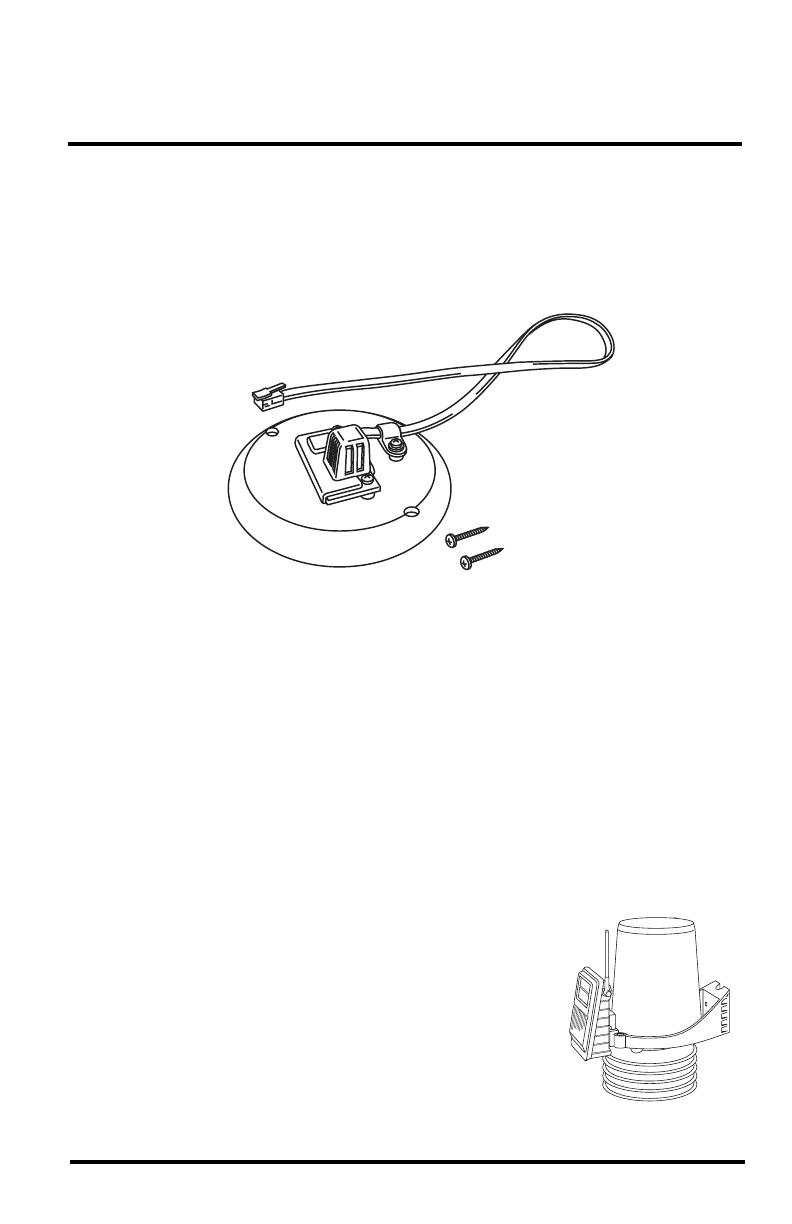
Insulated disk with mounted
Temperature/Humidity senso
r
#6 screws (2)
ISS
2
The Temperature/Humidity Station (# 6382)
contains a Temperature/Humidity sensor in a
radiation shield and connects to a provided SIM
shelter.
Optional — Put Console in Setup Mode
If you have a console, you need to put it in Setup Mode. This prevents the
reception of erroneous data while you are removing the ISS. To put your
console in Setup Mode:
At your Vantage Pro2 console, press and hold DONE and then press the
down arrow ( - ) to put the console in Setup Mode. The “Receiving from...”
screen will display.
Note: Additional information on clearing and setting console data can be found in the
Vantage Pro2 Console Manual.
If you have an Envoy and are concerned with erroneous data, you may edit the
data via the WeatherLink software. See the WeatherLink Online Help for more
information.
Take Down the ISS
Please work on your Vantage Pro2 ISS in a safe place. We strongly
recommend that you take the station down from its sited location before
replacing the sensor.
To take down the ISS:
1. Locate the SIM housing cover on the side of the ISS and open it.
2. Disconnect the Solar Panel wire on the SIM cover from the SIM board by
pulling the Solar Panel connector.
3. Pull the foam insert out of the cable access port in between the cables and
set the foam insert aside.
4. Disconnect the anemometer cable from the sensor connector labeled
WIND and slide the cable out of the cable access port.
5.
Cabled ISS Only: Disconnect the console cable from the SIM.
6. You can now remove the ISS from its mounted position. Move it to a safe
place to install the sensor.
Temperature/Humidity Station
3
Disassemble the Standard Radiation Shield — ISS
Note: We recommend using a workbench or table to perform the following procedures.
1. Open and remove the SIM cover if you have not done so already.
2. Disconnect the TEMP/HUM cable from the SIM
and slide the cable out of the cable access port.
3. Remove the rain collector cone from the ISS base
by rotating the cone counter-clockwise. When the
cone’s latches line up with openings in the base,
you can lift the cone off. The cone fits in the base
tightly and may require extra pressure to remove.
Steady the ISS base between your knees when
removing the cone.
4. Remove the three 8-32 x 4
''
screws holding the radiation
shield plates together from the
top of the rain collector base.
5. Separate out the radiation
shielding plates to locate the
Temperature/Humidity sensor
in the plating. See “Remove the
Previous Temperature/
Humidity Sensor” on page 4 for
instructions on removing the
previous sensor.
Twist to Open
4" Screw
Plates
Rain Collector Base
Temp/Humidity
Sensor
Lock
Washer
Flat
Washer
4
Disassemble the Radiation Shield — Temperature/Humidity
Station
Note: We recommend using a workbench or table to perform the following procedures.
1. Place the Temperature/
Humidity Station on a
level surface.
2. Loosen the three
mounting screws that
hold the mounting
bracket and the
radiation shield
together.
3. Separate the radiation
shield plates to locate
the Temperature/
Humidity sensor in the
plating. See “Remove
the Previous
Temperature/Humidity
Sensor” below for
instructions on
removing the previous sensor.
Remove the Previous Temperature/Humidity Sensor
1. Locate the Temperature/Humidity sensor on the second to bottom plate in
the radiation shield plating stack.
2. Remove the three screws and flat washer securing the Temperature/
Humidity sensor to the radiation plating.
Mounting
Bracket
Radiation
Shield
Assembly
Lock Washers
Flat Washers
4" Screws
Cable Clamp
T
emperature/Humidity
Sensor
5
Note: The orientation of the Temperature/Humidity sensor may be different from station to
station. Even if the sensor is inverted and attached to spacers it should still be removed
and replaced with the Temperature/Humidity sensor replacement kit.
3. Remove the sensor and cable clamp from the plate.
4. Return the plate to the radiation plating stack in the order it was mounted.
Insert the Temperature/Humidity Sensor
1. Locate the plate at the top of the radiation shield plating and find the
insulating disk on the underside of the plate.
2. Remove the two screws holding the insulating disk attached on the
underside and discard the disk.
3. Take the insulating disk with the mounted Temperature/Humidity sensor
and set it in the same place as the previous insulating disk.
Top Plate
Insulating Disk
6
4. Use the screws that were taken from the last insulating disk or use the
screws provided with the Temperature/Humidity Sensor Replacement Kit
to mount the Temperature/Humidity sensor in place.
5. Reassemble the radiation
shield plating.
6. Check the orientation of
the Temperature/
Humidity sensor cable.
When the plating is
reassembled, the cable
should be oriented on the
right side of the plating
so that it can be easily
placed between the top
radiation shield and the
rain collector base.
7. Replace the three 4''
screws, lock washers and
flat washers into their
respective holes in the
rain collector base and
screw the radiation shield
plates back into place.
Re-install the ISS
1. Install the rain collector
cone and lock it in place.
2. Slide the new
Temperature/Humidity
sensor cable back
through the cable access
port of the SIM box.
3. Connect the Temperature/Humidity sensor cable into the correct port.
4. Close the SIM cover temporarily without connecting the solar panel
cables.
5. Test communication between the ISS and the console. To test
communication, take the console out of Setup Mode (see “Take the
Console Out of Setup Mode” on page 7 for more information) and make
sure the console is receiving data from the ISS or Temperature/Humidity
Station. See the ISS manual or Temperature/Humidity Station Manual for
more information on testing communication.
4" Screw
(3)
Plates
Rain Collector Base
Temp/Humidity
Sensor Plate
Lock
Washer
Flat
Washer
7
6. Re-install the ISS in its previous location.
7. Open the SIM cover and connect the WIND (anemometer) cable.
8. Plug in the solar panel cable to the solar panel connector.
9.
Cabled ISS Only: Connect the console cable.
10. Re-insert the foam into the cable access port in the SIM box.
11. Close the SIM box.
12. Use cable ties to secure cables.
Take the Console Out of Setup Mode
1. At your Vantage Pro2 console, press and hold DONE for three seconds to
take the console out of Setup Mode.
2. Check the console for erroneous rain data and clear if necessary.
To clear erroneous daily rain data:
Select the RAINDAY button. The graph icon displays next to the daily
rain variable.
Press and release 2ND, then immediately press and hold CLEAR.
The daily rain variable will start blinking.
Keep holding CLEAR until the reading changes to zero.
Refer to your Vantage Pro2 Console Manual for more information on
clearing any other weather variables or clearing all weather variables in
the console.
You have completed the replacement kit.
This product complies with the essential protection requirements
of the EC EMC Directive 89/336/EC.
Vantage Pro2 Temperature Humidity Sensor Replacement Kit
Rev. A, February 1, 2008
Document Part Number: 07395.243
Used with Temperature/Humidity Sensor Replacement Kit # 6930
For Vantage Pro2 Stations # 6152, 6152C, 6162, 6162C, 6382
Vantage Pro
®
and Vantage Pro2
are trademarks of Davis Instruments Corp., Hayward, CA.
© Davis Instruments Corp. 2008. All rights reserved.
Information in this document subject to change without notice.
Tested to comply
with FCC standards
FOR HOME OR OFFICE USE
3465 Diablo Avenue, Hayward, CA 94545-2778 U.S.A.
510-732-9229 • Fax: 510-732-9188
E-mail: [email protected] • www.davisnet.com
Contacting Davis Technical Support
If you have any questions, or encounter problems with your Vantage Pro2
weather station, or with the current firmware installation, please contact Davis
Technical Support. We’ll be glad to help.
(510) 732-7814 — Monday - Friday, 7:00 a.m. - 5:30 p.m. Pacific Time. We
are unable to accept collect calls.
(510) 670-0589 — Technical Support Fax.
[email protected] — E-mail to Technical Support.
[email protected] — General e-mail.
www.davisnet.com — Davis Instruments web site. See the Weather Support
section for copies of user manuals, product specifications, application notes,
and information on software updates. Watch for FAQs and other updates.
  • Page 1 1
  • Page 2 2
  • Page 3 3
  • Page 4 4
  • Page 5 5
  • Page 6 6
  • Page 7 7
  • Page 8 8

DAVIS Vantage Pro2 Temperature/Humidty Sensor Replacement Kit Owner's manual

Category
Dehumidifiers
Type
Owner's manual
This manual is also suitable for

Ask a question and I''ll find the answer in the document

Finding information in a document is now easier with AI