Page is loading ...

Operating Instructions
Bedienungsanleitung
Manuel d‘utilisation
Type 8026 - 8036 - SE36
Flowmeter and Flow transmitter
Durchfluss-Messgerät und Durchfluss-Transmitter
Débitmètre et transmetteur de débit

We reserve the right to make technical changes without notice.
Technische Änderungen vorbehalten.
Sous réserve de modification technique.
© Bürkert SAS, 2009 - 2016
Operating Instructions 1603/02_EU-ML 00561367 / Original_FR

3
Type 8026 - 8036 - SE36
1 ABOUT THIS MANUAL .....................................................................................................................................................................7
1.1 Definition of the word "device" .......................................................................................................................................7
1.2 Validity of the manual ..........................................................................................................................................................7
1.3 Symbols used ..........................................................................................................................................................................7
2 INTENDED USE ....................................................................................................................................................................................8
3 BASIC SAFETY INFORMATION ....................................................................................................................................................9
4 GENERAL INFORMATION .............................................................................................................................................................10
4.1 Manufacturer's address and international contacts .........................................................................................10
4.2 Warranty conditions ...........................................................................................................................................................10
4.3 Information on the Internet ............................................................................................................................................10
5 DESCRIPTION ....................................................................................................................................................................................11
5.1 Area of application .............................................................................................................................................................11
5.2 General description ...........................................................................................................................................................11
5.2.1 Construction of the 8026 .................................................................................................................11
5.2.2 Construction of the SE36 ................................................................................................................12
5.2.3 Construction of the 8036 .................................................................................................................12
5.2.4 Construction of the SE36 with sensor-fitting S070 or S077 ..................................................12
5.3 Description of the name plate .....................................................................................................................................13
5.4 Available versions of type 8026 ..................................................................................................................................14
5.5 Available versions of the transmitter SE36 ..........................................................................................................15
6 TECHNICAL DATA .............................................................................................................................................................................16
6.1 Conditions of use ................................................................................................................................................................16
6.2 Conformity to standards and directives .................................................................................................................16
6.2.1 Conformities common to the 8026 and the SE36 .....................................................................16
6.2.2 Conformity to the pressure equipment directive .........................................................................16
6.3 Mechanical data ...................................................................................................................................................................17
6.4 Fluid data .................................................................................................................................................................................18
6.5 Electrical data .......................................................................................................................................................................19
Contents
English

4
7 ASSEMBLY ...........................................................................................................................................................................................20
7.1 Safety instructions .............................................................................................................................................................20
7.2 Removing the cover ...........................................................................................................................................................20
7.3 Mounting the cover ............................................................................................................................................................21
7.4 Mounting the display module .......................................................................................................................................21
7.5 Removing the display module .....................................................................................................................................22
8 INSTALLATION AND WIRING ......................................................................................................................................................23
8.1 Safety instructions .............................................................................................................................................................23
8.2 Installation of a 8026 on a pipe ...................................................................................................................................24
8.2.1 Install the fitting S020 in the pipe ..................................................................................................24
8.2.2 Install the flowmeter 8026 into the fitting S020 ........................................................................25
8.2.3 Complete the installation of the 8026 ...........................................................................................25
8.3 Installation of a 8036 on a pipe ...................................................................................................................................26
8.3.1 Install the sensor-fitting S030 in the pipe ....................................................................................26
8.3.2 Assemble the flow transmitter SE36 on the sensor-fitting S030 ...........................................26
8.3.3 Complete the installation of the 8036 ...........................................................................................27
8.4 Installation of a flow transmitter SE36 with sensor-fitting S070 or S077 in a pipe .......................27
8.4.1 Install the sensor-fitting S070 or S077 in a pipe .......................................................................27
8.4.2 Assemble the flow transmitter SE36 on the sensor-fitting S070 or S077 ..........................28
8.4.3 Complete the installation of the flow transmitter SE36 with sensor-fitting
S070 or S077 .....................................................................................................................................28
8.5 Wiring .........................................................................................................................................................................................28
8.5.1 Electrical connections .......................................................................................................................29
8.5.2 Assembling the male or female connector (accessories: see chap. 11) ..............................29
8.5.3 Equipotentiality of the installation ...................................................................................................29
8.5.4 Wiring a version with a single M12 fixed connector and an NPN transistor
output and a current output .............................................................................................................31
8.5.5 Wiring a version with a single M12 fixed connector and two transistor out-
puts and one current output ............................................................................................................32
8.5.6 Wiring a version with two M12 fixed connectors and two transistor outputs
and two current outputs ....................................................................................................................34
9 ADJUSTMENT AND COMMISSIONING .................................................................................................................................37
9.1 Safety instructions .............................................................................................................................................................37
9.2 When switching on the device .....................................................................................................................................37
English
Type 8026 - 8036 - SE36

5
9.3 Knowing the operating levels .......................................................................................................................................38
9.4 Using the navigation button ..........................................................................................................................................39
9.5 Using the dynamic functions ........................................................................................................................................40
9.6 Entering a numerical value (example) .....................................................................................................................41
9.7 Browsing in a menu (example) ...................................................................................................................................41
9.8 Knowing the icons and LEDs .......................................................................................................................................42
9.9 Knowing the Process level ............................................................................................................................................43
9.10 Accessing the Configuration level .............................................................................................................................44
9.11 Knowing the structure of the Configuration menus ........................................................................................45
9.12 Knowing the menu Parameter .....................................................................................................................................49
9.12.1 Transferring data from one device to another ..............................................................................49
9.12.2 Modifying the access code of menu "Param" ..............................................................................50
9.12.3 Restoring the default parameters of the Process level and the outputs ...............................50
9.12.4 Setting the data displayed in Process level .................................................................................51
9.12.5 Choosing the units for the totalizers displayed in Process level .............................................53
9.12.6 Displaying the lowest and highest values measured .................................................................53
9.12.7 Setting the contrast and the backlight of the display ................................................................54
9.12.8 Defining the connection mode of the outputs .............................................................................54
9.12.9 Setting the parameters of the current outputs ............................................................................55
9.12.10 Setting the parameters of the transistor outputs ........................................................................56
9.13 Knowing the menu Calibration ....................................................................................................................................58
9.13.1 Activating/deactivating the Hold function .....................................................................................58
9.13.2 Modifying the Calibration menu access code .............................................................................59
9.13.3 Resetting totalizer 1 or totalizer 2 respectively ............................................................................59
9.13.4 Adjusting the current outputs ..........................................................................................................59
9.13.5 Entering the K-factor or determining it with Teach-In ................................................................60
9.14 Knowing the menu Diagnostic ....................................................................................................................................63
9.14.1 Modifying the Diagnostic menu access code ..............................................................................63
9.14.2 Monitoring the sensor input frequency ..........................................................................................63
9.15 Knowing the menu Test ...................................................................................................................................................64
9.15.1 Modifying the Test menu access code ..........................................................................................64
9.15.2 Checking the output functions ........................................................................................................64
9.15.3 Checking the outputs behaviour .....................................................................................................65
9.16 Knowing the menu Information ...................................................................................................................................66
English
Type 8026 - 8036 - SE36

6
10 MAINTENANCE AND TROUBLESHOOTING .......................................................................................................................67
10.1 Safety instructions .............................................................................................................................................................67
10.2 Cleaning the device ...........................................................................................................................................................67
10.3 Solving problems ................................................................................................................................................................68
11 SPARE PARTS AND ACCESSORIES ......................................................................................................................................70
12 PACKAGING, TRANSPORT ..........................................................................................................................................................70
13 STORAGE ..............................................................................................................................................................................................70
14 DISPOSAL OF THE PRODUCT ..................................................................................................................................................71
English
Type 8026 - 8036 - SE36

7
About this manual
1 ABOUT THIS MANUAL
This manual describes the entire lifecycle of the device. Please keep this manual in a safe place, accessible to all
users and any new owners.
This manual contains important safety information.
Failure to comply with these instructions can lead to hazardous situations. Pay attention in particular to the
chapters "Basic safety information" and "Intended use".
▶ Whatever the version of the device, this manual must be read and understood.
1.1 Definition of the word "device"
The word "device" used within this manual refers to the flowmeter type 8026, the flowmeter type 8036 or the
flow transmitter type SE36.
1.2 Validity of the manual
The manual is valid for the following devices:
• flowmeter 8026 from the version V2,
• flowmeter 8036 from the version V2,
• flow transmitter SE36 from the version V2.
These informations are available on the name plate, see chap. 5.3.
1.3 Symbols used
DANGER
Warns against an imminent danger.
▶ Failure to observe this warning can result in death or in serious injury.
WARNING
Warns against a potentially dangerous situation.
▶ Failure to observe this warning can result in serious injury or even death.
ATTENTION
Warns against a possible risk.
▶ Failure to observe this warning can result in substantial or minor injuries.
NOTE
Warns against material damage.
▶ Failure to observe this warning may result in damage to the device or system.
English
Type 8026 - 8036 - SE36

8
About this manual
Indicates additional information, advice or important recommendations.
Refers to information contained in this manual or in other documents.
▶ Indicates an instruction to be carried out to avoid a danger, a warning or a possible risk.
→ Indicates a procedure to be carried out.
Indicates the result of a specific instruction.
2 INTENDED USE
Use of the device that does not comply with the instructions could present risks to people, nearby
installations and the environment.
Flowmeters 8026 and 8036 and flow transmitter SE36 associated with a sensor-fitting are intended to
measure the flow rate of liquids.
▶ Use this device in compliance with the characteristics and commissioning and use conditions specified in the
contractual documents and in the user manual.
▶ Never use this device for security applications.
▶ Protect this device against electromagnetic interference, ultraviolet rays and, when installed outdoors, the
effects of climatic conditions.
▶ Use this device only if in perfect working order.
▶ Requirements for the safe and proper operation of the device are proper transport, storage and installation, as
well as careful operation and maintenance.
▶ Only use the device as intended.
English
Type 8026 - 8036 - SE36

9
Basic safety information
3 BASIC SAFETY INFORMATION
This safety information does not take into account:
• any contingencies or occurrences that may arise during installation, use and maintenance of the devices.
• the local safety regulations for which the operating company is responsible including the staff in charge of
installation and maintenance.
Danger due to electrical voltage.
▶ If a 12-36 V DC or a 14-36 V DC powered version is installed either in a wet environment or outdoors, all the
electrical voltages must be of max. 35 V DC.
▶ Disconnect the electrical power for all the conductors and isolate it before carrying out work on the system.
▶ Observe all applicable accident protection and safety regulations for electrical equipment.
Danger due to high pressure in the installation.
▶ Stop the circulation of fluid, cut off the pressure and drain the pipe before loosening the process connections.
Danger due to high temperatures of the fluid.
▶ Use safety gloves to handle the device.
▶ Stop the circulation of fluid and drain the pipe before loosening the process connections.
Danger due to the nature of the fluid.
▶ Respect the prevailing regulations on accident prevention and safety relating to the use of aggressive fluids.
Various dangerous situations
To avoid injury take care:
▶ not to use the device for the measurement of gas flow rates.
▶ not to use the device in explosive atmospheres.
▶ not to use the device in an environment incompatible with the materials it is made of.
▶ not to use fluid that is incompatible with the materials the device is made of.
▶ not to make any modifications to the device.
▶ not to subject the device to mechanical loads.
▶ to prevent any unintentional power supply switch-on.
▶ to carry out the installation and maintenance work by qualified and skilled staff with the appropriate tools.
▶ to guarantee a defined or controlled restarting of the process, after a power supply interruption.
▶ to observe the general technical rules when installing and using the device.
English
Type 8026 - 8036 - SE36

10
Basic safety information
NOTE
The device may be damaged by the fluid in contact with.
▶ Systematically check the chemical compatibility of the component materials of the device and the fluids likely
to come into contact with it (for example: alcohols, strong or concentrated acids, aldehydes, alkaline com-
pounds, esters, aliphatic compounds, ketones, halogenated aromatics or hydrocarbons, oxidants and chlorin-
ated agents).
NOTE
Elements / Components sensitive to electrostatic discharges
▶ This device contains electronic components sensitive to electrostatic discharges. They may be damaged if
they are touched by an electrostatically charged person or object. In the worst case scenario, these compo-
nents are instantly destroyed or go out of order as soon as they are activated.
▶ To minimise or even avoid all damage due to an electrostatic discharge, take all the precautions described in
standard EN 61340-5-1.
▶ Also ensure that you do not touch any of the live electrical components.
4 GENERAL INFORMATION
4.1 Manufacturer's address and international contacts
To contact the manufacturer of the device, use following address:
Bürkert SAS
Rue du Giessen
BP 21
F-67220 TRIEMBACH-AU-VAL
You may also contact your local Bürkert sales office.
The addresses of our international sales offices are available on the internet at:
www.burkert.com
4.2 Warranty conditions
The condition governing the legal warranty is the conforming use of the device in observance of the operating
conditions specified in this manual.
4.3 Information on the Internet
You can find the user manuals and technical data sheets regarding the types 8026, 8036 and SE36 at:
www.burkert.com
English
Type 8026 - 8036 - SE36

11
Description
5 DESCRIPTION
5.1 Area of application
8026, 8036 and SE36 devices are intended to measure the flow rate of liquids:
• flowmeters 8026 and 8036 are used to measure the flow of neutral or slightly aggressive liquids,
• flow transmitter SE36 with sensor-fitting S070 or S077 is used to measure the flow rate of viscous liquids such
as honey or oil and which are free of solid particles.
Thanks to one or two fully adjustable transistor outputs, the device can be used to switch a solenoid valve,
activate an alarm and, thanks to one or two 4-20-mA current outputs, establish one or two control loops.
5.2 General description
5.2.1 Construction of the 8026
The flowmeter 8026 comprises:
A
C
B
A: a paddle-wheel flow sensor, the rotation of which generates pulses.
Set in rotation by the flow, the 4 permanent magnets integrated in the vanes of the
paddle generate pulses, the frequency of which is proportional to the flow velocity
of the fluid. A conversion coefficient specific to each pipe (material and diameter) is
necessary to establish the flow rate value associated with the measurement.
The conversion coefficient (K-factor) expressed in pulses per litre is given in the user
manual for the fitting used.
B: an acquisition / conversion module for the process values measured:
• acquisition of the pulse frequency
• conversion of the frequency measured into flow rate units
C: an electrical housing which can include a display module. The display module
has a navigation button to read and/or configure the parameters of the device. The
display module is not delivered with all the versions of the flowmeter but is available
as accessory (see chap. 11).
English
Type 8026 - 8036 - SE36

12
Description
5.2.2 Construction of the SE36
The flow transmitter SE36 comprises:
A
B
A: an acquisition / conversion module for the process values measured:
• acquisition of the pulse frequency
• conversion of the frequency measured into flow rate units
B: an electrical housing which can include a display module. The display module
has a navigation button to read and/or configure the parameters of the device. The
display module is not delivered with all the versions of the flowmeter but is available
as accessory (see chap. 11).
5.2.3 Construction of the 8036
The flowmeter 8036 comprises:
A
B
A: an S030 sensor-fitting including the paddle-wheel flow sensor.
Set in rotation by the flow, the 4 permanent magnets integrated in the vanes of the
paddle generate pulses, the frequency of which is proportional to the flow velocity
of the fluid. A conversion coefficient specific to each pipe (material and diameter) is
necessary to establish the flow rate value associated with the measurement.
The conversion coefficient (K-factor) expressed in pulses per litre is given in the user
manual for the sensor-fitting used.
B: a flow transmitter SE36 (see chap. 5.2.2)
5.2.4 Construction of the SE36 with sensor-fitting S070 or S077
The flow transmitter SE36 with sensor-fitting S070 or S077 comprises:
A
B
S077
S070
A: an S070 or S077 sensor-fitting including the flow sensor with
oval gears.
Set in rotation by the flow, the magnets integrated in the oval
gears generate pulses, the frequency of which is proportional to
the volume of fluid. A conversion coefficient specific to each pipe
(material and diameter) is necessary to establish the flow rate
value associated with the measurement.
The conversion coefficient (K-factor) expressed in pulses per litre
is given in the user manual for the sensor-fitting used.
B: a flow transmitter SE36 (see chap. 5.2.2)
English
Type 8026 - 8036 - SE36

13
Description
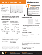
5.3 Description of the name plate
8026 Flow-Meter V2
Supply: 14-36VDC
Output: 1x4-20mA 2xTransistors 500 mA Max
Cell: HALL INSERTION SHORT
Process: Temp -15/100°C
PN 10 Bar
IP65-IP67 W41MT
S-N:2024
00560861
Made in France
1
2
3
4
5
6
7
8
9
10
11
1:V+
2:NPN/PNP1
3:0V
4:NPN/PNP2
SE36/8036 Flow-Meter With Display V2
Supply: 14-36V
Output: 1x4-20mA 1xTransistor 700 mA Max NPN
Cell: HALL INLINE
Process: Temp -15/110°C
PN 16 Bar
IP65-IP67 W4YME
S-N:2608
00561880
Made in France
1
2
3
4
5
6
7
8
9
10
11
1:V+
2:NPN1
3:0V
Flowmeter 8026 Flowmeter 8036 or flow transmitter SE36
Fig. 1 : Examples of a name plate
1. Type of the device, measured variable and version
2. Power supply
3. Output specifications
4. Type of sensor
5. Fluid temperature range
6. Fluid pressure
7. Allocation of the pins on the M12 fixed connectors
8. Manufacturing code
9. Order code
10. Serial number
11. Protection rating
English
Type 8026 - 8036 - SE36

14
Description
5.4 Available versions of type 8026
The following versions of the 8026 flowmeter are available. Each version of the 8026 flowmeter is available
without or with the display module.
The display module is also available as an accessory (see chap. 11).
Voltage supply
Outputs
Electrical connection
Type of sensor
Seal of the sensor
UL
Type of connection of
the outputs
Order code of the
8026
without
display
module
with display
module
14-36 V DC 1 NPN transistor +
1 x 4-20 mA
Male 5-pin M12
fixed connector
Short FKM
1)
no 2-wire
560 860 561 860
Long FKM
1)
560 870 561 870
Short FKM
1)
yes 2-wire
560 863 561 863
Long FKM
1)
560 873 561 873
2 x transistor,
NPN/PNP, + 1 x
4-20 mA
Male 5-pin M12
fixed connector
Short FKM
1)
no 2-wire
560 861 561 861
Long FKM
1)
560 871 561 871
Short FKM
1)
yes 2-wire
560 864 561 864
Long FKM
1)
560 874 561 874
12-36 V DC 2 x transistor,
NPN/PNP, + 2 x
4-20 mA
Male 5-pin M12
fixed connector +
female 5-pin M12
fixed connector
Short FKM
1)
no 3-wire
560 862 561 862
Long FKM
1)
560 872 561 872
Short FKM
1)
yes 3-wire
560 865 561 865
Long FKM
1)
560 875 561 875
1)
A set with additional seals (1 green FKM seal + 1 black EPDM seal) is delivered with each device.
English
Type 8026 - 8036 - SE36

15
Description
5.5 Available versions of the transmitter SE36
The following versions of the transmitter SE36 are available. The references of the S030 and S077 sensor-fittings
including the flow sensor can be found on the related technical data sheets for these product types.
Each version of the transmitter is available without or with the display module.
The display module is also available as an accessory (see chap. 11).
Voltage supply
Outputs
Electrical connection
Type of connection of the
outputs
UL
Order code of the SE36
without
display
module
with display
module
14-36 V DC 1 NPN transistor
+ 1 x 4-20 mA
Male 5-pin M12
fixed connector
2-wire no
560 880 561 880
yes
560 883 561 883
2 x transistor,
NPN/PNP, + 1 x
4-20 mA
Male 5-pin M12
fixed connector
2-wire no
560 881 561 881
yes
560 884 561 884
12-36 V DC 2 x transistor,
NPN/PNP, + 2 x
4-20 mA
Male 5-pin M12
fixed connector +
female 5-pin M12
fixed connector
3-wire no
560 882 561 882
yes
560 885 561 885
English
Type 8026 - 8036 - SE36

16
Technical data
6 TECHNICAL DATA
6.1 Conditions of use
Ambient temperature -10 to +60 °C
Air humidity < 85%, non condensated
Protection rating according to
EN 60529
IP67 and IP65 with connectors plugged in and tightened and transmitter
cover fully closed and sealed
6.2 Conformity to standards and directives
6.2.1 Conformities common to the 8026 and the SE36
• EMC: EN 61000-6-2, EN 61000-6-3
• Vibration: EN 60068-2-6
• Shock: EN 60068-2-27
For UL devices (
) in the United States of America and Canada:
• UL 61010-1
• CAN/CSA-C22.2 n° 61010-1
6.2.2 Conformity to the pressure equipment directive
The devices 8026 and the sensor-fittings S030, S070 and S077 comply with article 3§3 of the pressure
equipment directive 97/23/CE.
According to this directive, the product can only be used in the following cases (depending on max. pressure,
pipe diameter and fluid):
Type of fluid Conditions
Fluid group 1, par. 1.3.a • Flowmeter 8026 and sensor-fitting S030: DN ≤ 25 only
• Sensor-fittings S070 and S077: Forbidden
Fluid group 2 par. 1.3.a DN ≤ 32
or DN > 32 and PNxDN ≤ 1000
Fluid group 1 par. 1.3.b • Flowmeter 8026: DN ≤ 25 or DN > 25 and PNxDN ≤ 2000
• Sensor-fittings S030, S070 and S077: PNxDN ≤ 2000
Fluid group 2 par. 1.3.b • Flowmeter 8026: DN ≤ 400
• Sensor-fittings S030, S070 and S077: DN ≤ 200
English
Type 8026 - 8036 - SE36

17
Technical data
6.3 Mechanical data
Part Material
Box / seals stainless steel 1.4404, PPS / EPDM
Cover / seal PC / silicone
Display module PC / PBT
M12 fixed connector nickel-plated brass (stainless steel on request)
Fixed connector holder stainless steel 1.4404 (316L)
Screws stainless steel
Nut PC
Flow sensor holder / seal (only 8026) PVDF / FKM (default)
Axis and shaft of the paddle wheel (only 8026) Ceramic (Al
2
O
3
)
Paddle wheel (only 8026) PVDF
Quarter-turn system (only SE36) PC
PC
silicone
PPS
EPDM
PVDF
PC
stainless steel
nickel-plated
brass
(stainless steel)
PPS
PVDF
ceramic (Al
2
O
3
)
FKM
PC
silicone
PPS
EPDM
stainless steel
nickel-plated
brass
(stainless steel)
PC
Flowmeter 8026 Transmitter SE36
Fig. 2 : Materials used in the flowmeter 8026 and the transmitter SE36
• Materials in contact with the fluid (only for 8026): PVDF, ceramic, FKM (default).
• Dimensions of devices: please refer to the technical data sheets regarding the types 8026, 8036 or SE36
avalaible at www.burkert.com
• Mechanical data of fittings: please refer to the technical data sheets regarding the related fittings, avalaible at
www.burkert.com
English
Type 8026 - 8036 - SE36

18
Technical data
6.4 Fluid data
Pipe diameter
DN06 to DN400;
For fitting S020 or sensor-fitting S030, the appropriate diameter
is determined using the flow rate / DN / fluid velocity graphs:
refer to the manuals of the fittings
Fluid temperature
• 8026
• -15 to +100 °C; Also factor in the fluid temperature/pressure
dependency for the 8026 with fitting S020 : see Fig. 3
• 8036 • see the manual delivered with the sensor-fitting S030 or the
technical data sheet
• SE36 with a sensor-fitting S070 or S077 • see the manual delivered with the sensor-fitting S070 or S077
or the technical data sheet
Fluid pressure
Also refer to the requirements of the Pressure Equipment
Directive: see chap. 6.2.2
• 8026
• PN10; Also factor in the fluid temperature/pressure
dependency for the 8026 with fitting S020 (see Fig. 3)
• 8036 • see the manual delivered with the sensor-fitting S030 or the
technical data sheet
• SE36 with a sensor-fitting S070 or S077 • see the manual delivered with the sensor-fitting S070 or S077
or the technical data sheet
Type of fluid
• 8026 and 8036 • Neutral or slightly aggressive fluids
• SE36 with sensor-fitting S070 or S077 • Viscous fluids, free of solid particles
Fluid viscosity
• 8026 and 8036 • 300 cSt max.
• SE36 with sensor-fitting S070 or S077 • see the manual delivered with the sensor-fitting S070 or S077
or the technical data sheet
Solid particle rate in the fluid
• 8026 and 8036 • ≤ 1%
• SE36 with sensor-fitting S070 or S077 • 0 %
Flow rate measurement
• Measurement range • 0,3 to 10 m/s
• Linearity • ±0,5%
1)
of the full scale
• Repeatability • ±0,4%
1)
of the measured value
• Measurement deviation with standard K-factor • ±2,5%
1)
of the measured value
• Measurement deviation with a Teach-In
procedure
• ±1%
1)
of the measured value (at the Teach-In point)
1)
Determined in the following reference conditions: fluid = water, water and ambient temperatures = 20 °C, upstream and
downstream distances respected, appropriate pipe dimensions.
English
Type 8026 - 8036 - SE36

19
Technical data
10
9
8
7
6
5
4
3
2
1
0
-10 +10 +30 +50 +70 +90 +110
A
PVC (PN10)
PP (PN10)
T (°C)
P (bar)
PVC + PP
PVDF (PN10)
(PN10)
PVDF +
Metal
Metal
A: Operating range
Fig. 3 : Fluid temperature-pressure dependency for the flowmeter 8026 associated to a fitting S020
6.5 Electrical data
Power supply
• version with 2 or 3 outputs (2 wires) • 14-36 V DC, filtered and regulated
• version with 4 outputs (3 wires) • 12-36 V DC, filtered and regulated
Specifications of the power source
(not supplied) of the UL devices
• limited energy source (in accordance to UL 61010-1,
paragraph 9.3)
or
• Class 2 source (in accordance to standards 1310/1585 and
60950-1)
Current consumption
• version with 2 or 3 outputs (2 wires) • 25 mA max. (at 14 V DC)
• version with 4 outputs (3 wires) • 5 mA max. (at 12 V DC)
Current consumption, with loads on
the transistors
1 A max.
Power consumption
40 W max.
Protection against polarity reversal
yes
Protection against voltage spikes
yes
Protection against short circuits
yes, transistor outputs
Transistor output
• Version with only 1 transistor output • NPN, open collector, 700 mA max., 1-36 V DC
• Version with 2 transistor outputs • NPN (/sink) or PNP (/source) (depending on parameter setting),
open collector, 700 mA max., 500 mA max. per transistor if both
transistor outputs are wired.
NPN output: 1-36 V DC
PNP output: supply voltage
Current output
4-20 mA, sink ("NPN sink") or source ("PNP source") (depending
on parameter setting)
• Version with only 1 current output (2
wires)
• max. loop impedance: 1100 W at 36 V DC, 610 W at 24 V DC,
180 W at 14 V DC
• version with 2 current outputs (3 wires) • max. loop impedance: 1100 W at 36 V DC, 610 W at 24 V DC,
100 W at 12 V DC
English
Type 8026 - 8036 - SE36

20
Assembly
7 ASSEMBLY
7.1 Safety instructions
DANGER
Risk of injury due to electrical voltage.
▶ Shut down and isolate the electrical power source before carrying out work on the system.
▶ Observe all applicable accident protection and safety regulations for electrical equipment.
WARNING
Risk of injury due to non-conforming assembly.
▶ The device must only be assembled by qualified and skilled staff with the appropriate tools.
Risk of injury due to unintentional switch on of power supply or uncontrolled restarting of the
installation.
▶ Take appropriate measures to avoid unintentional activation of the installation.
▶ Guarantee a defined or controlled restarting of the process after any intervention on the device.
7.2 Removing the cover
NOTE
The tightness of the device is not guaranteed when the cover is removed.
▶ Once the cover is removed, prevent ingress of liquid inside the housing.
The device may be damaged if a metal component comes into contact with the electronics.
▶ Prevent contact of the electronics with a metal component.
2
1
→ [1] Turn the cover counterclockwise with
an angle of about 15° to unlock it.
→ [2] Remove the cover.
If the cover grips to the housing:
→ Use an appropriate tool to unlock the
cover, taking care not to scratch the glass.
→ Insert an apropriate tool into the groove of
the housing.
→ Lever the cover up.
Fig. 4 : Removing the cover
English
Type 8026 - 8036 - SE36
/