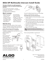
Page is loading ...

- 1 -
8036 SIP Multimedia
Intercom
User Guide
Algo Communication Products Ltd.
www.algosolutions.com
90-00081C

- 2 -
T
able of Contents
Overview ........................................................................ 4
Introduction .............................................................................4
Key Features .............................................................................4
What’s Included .......................................................................5
Product Tour ............................................................................. 6
Setup and Installation .................................................... 7
Wall Mounting .........................................................................7
PoE Network Connection ........................................................15
Programming and Configuration ................................. 16
Web Interface Control Panel ...................................................16
Accessing the Control Panel .................................................... 16
Setup SIP Account...................................................................18
Application Development ............................................. 19
Overview ...............................................................................19
Creating User Interface Screens ..............................................20
Custom Graphic Screens.........................................................20
Directory (Addressbook) Listings .............................................21
Uploading user content ..........................................................22
Control Panel Menu Reference ..................................... 23
Status ..................................................................................... 23
Settings ..................................................................................24
User Interface.........................................................................33
System ...................................................................................42
Door Control ................................................................. 45
Configuring the 8061 .............................................................46
Configuring the 8036 with the 8061 ....................................... 47
Door Control Hardware and Wiring ........................................47
Appendix ...................................................................... 48
Upgrade 8036 Firmware ........................................................48
Soft Reset ...............................................................................49
Button Positioning Table ..........................................................50

- 3 -
Directory (Addressbook) Text Files ...........................................53
Working with Compressed Files ..............................................55
Specifications .........................................................................57
FCC Compliance ....................................................................59
Important Safety Notice .......................................................... 59

- 4 -
Overview
Introduction
The 8036 is a multimedia SIP endpoint from Algo
combining the functionality of an IP phone,
security camera, and interactive kiosk.
Easily configurable to support multiple
applications and interface configurations,
the product is designed for outdoor or
public access locations to provide
enhanced communication and support for
guests and visitors.
Key Features
• Sunlight viewable 5.7” VGA color
capacitive touch display
•
Integrated camera for still snapshot or H.264 video
streaming
• Weatherproof
• Wideband speaker and dual microphones
• Presence detection
• Secure door/gate management
• Web interface panel for configuration and application
programming
For comprehensive product and application information,
please visit www.algosolutions.com/8036

- 5 -
What’s Included
For information on the use of each of these components,
please refer to “Setup and Installation” on page 7.
Algo
Security
Tool
Ethernet
Cable Boot
#8 x 1
Type B
P
an Head
Phillips
Qty: 6
#8 x 1.5
Type A
Pan Head
Phillips
Qty: 6
Drywall
Bracket
Surface
Mount
Bracket
Mounting
Gasket
8036
Assembly
with
Front Bezel

- 6 -
Product Tour
Front View
Presence Detection
VGA H.264 Camera
“HD” Dual Microphones
Nickel Plated Cover
“HD
” Speaker
Algo Logo Badge
covering Security Screw
Sunlight Viewable
T
ouch Display
SIP PoE
(Connector on Back)
Back View (of 8036 Assemby)
W
eatherproof
Ethernet Cable
Boot
PoE Network
Jack

- 7 -
Setup and Installation
This section will guide you with the physical installation of
your new 8036 SIP Multimedia Intercom.
Wall Mounting
The 8036 can be either surface or flush mounted. The unit
is designed to shed rainwater and allow air ventilation only
when oriented in the correct position (ALGO logo at top) and
installed vertically.
Removal of Front Bezel for Installation
The 8036 is shipped partially assembled and must be
partially
disassembled before
it can be installed.
Remove the security
screw behind the
ALGO Logo Badge
by first pressing
on one side of the
badge. This will raise
the other side so that
it can be removed
easily by hand.
A security bit (“Algo
Security Tool”) is
included with the
8036 that fits standard socket screwdrivers. Use the bit in a
screwdriver to remove the security screw and carefully remove
the Front Bezel by pulling at the top and then disengaging the
bottom clip.

- 8 -
Algo
Security
T
ool
Put the Front Bezel, Security Screw, and Logo Badge aside for
re-assembly after mounting.
Refer to the following diagrams for the appropriate methods
and components to use for different mounting applications.
Flush Mounting into Drywall (Interior)
1. Create a drywall cut out per the template on page 4 of
this sheet.
2.
Place the Drywall Bracket into wall and bend tabs around
to the front of the drywall to hold in place.
3. After connecting the Ethernet cable, use the #8 x 1.5”
Type A Pan Head screws to secure the 8036 housing to
the Drywall Bracket.
4. Replace the Front Bezel and keep the Algo Security Tool in
a safe location.
5. Replace the ALGO Logo Badge.
The Mounting Gasket and Surface Mount Bracket are
not required for drywall mounting.

- 9 -
Flush Mounting an 8036 into an interior wall (drywall)
Front Bezel
#8 x 1.5” Type A Pan Head
(Typical) Six needed
8036 Assembly
Logo Badge
Security Screw
Under Logo Badge
Drywall
Bracket
Drywall
A template for cutting a hole in the wall can be
downloaded at
www
.algosolutions.com/8036mounting

- 10 -
Flush Mounting into Other Materials or Outdoors
The same guidelines of flush mounting from the previous
section apply
, however
, the Drywall Bracket may not be
required if the wall material is firm enough to hold a screw
close to the cutout edge. A #8 anchor may be required (not
supplied) for the wall material.
If outdoors:
1.
A rubber Ethernet Cable boot is supplied to be placed
over the network cable prior to terminating with a plug
(see “P
oE Network Connection
” on page 15).
2.
While the 8036 is designed to withstand rain, it may be
undesirable for water to enter the wall cavity. This can be
achieved by sealing the cable hole prior to mounting or
using the Mounting Gasket between the 8036 and wall.
Uneven surfaces may require a silicon bead around the
8036 after installation.
Flush Mounting an 8036 into Drywall
Front Bezel
#8 x 1.5” Type A Pan Head
(Typical) Six needed
8036 Assembly
Logo Badge
Security Screw
Under Logo Badge
Drywall
Bracket
Drywall

- 11 -
Flush Mounting an 8036 into Drywall
#8 x 1.5” Type A Pan Head
(Typical) Six needed
Mounting Gasket
Anchors as
R
equired
Apply thin silicone seal around
opening (mount, then seal)

- 12 -
Surface Mounting
The Surface Mount Bracket may be used on a wall surface
where flush mounting is undesirable, or not practical. The
bracket also may be good option when integrating the 8036
into stonework.
1.
Mount the Surface Mount Bracket using the #8 x 1.5”
Type A Pan Head screws supplied. For some wall
materials, #8 anchors may be required (not included).
There is a top and bottom to the Surface Mount Bracket. Make
sure the two drainage holes are at the bottom.
If outdoors:
a. Ensure any opening in the wall is sealed or apply a
silicon bead between the Surface Mount Bracket and
wall surface around the outside perimeter.
b.
The Ethernet Cable Boot is to be placed over the
network cable prior to terminating with a plug (see
“PoE Network Connection” on page 15).
c.
To prevent water from getting behind the 8036, place
the Mounting Gasket on to the back of the 8036
housing prior to mounting.
2.
After connecting the Ethernet cable, use the #8 x 1” Type
B Pan Head screws to secure the 8036 housing to the
Surface Mount Bracket.
3. Replace the F
ront Bezel and keep the Algo Security Tool in
a safe location. Replace the ALGO Logo Badge.
The Drywall Bracket is not required when surface mounting.

- 13 -
Surface mounting an 8036 on outside wall
#8 x 1.5” T
ype A P
an Head
(Typical) Six needed
#8 x 1” Type B Pan Head
(Typical) Six needed
Surface Mount Bracket
Optional: Apply thin silicone seal around
perimeter (mount, then seal)
Mounting Gask
et

- 14 -
Mounting Height
The 8036 should be mounted at an appropriate height for
your intended application. The considerations are:
1.
Easy readability of the interface screens for users of
different heights
2. Highest quality camera and video images.
For most applications, a mounting height of approximately
55 inches (1.4 m) from floor to center of display is
recommended.
Mounting the 8036 at the proper height
0
1
2
3
4
5
6
1
2
3 0
Measurements in Ft.
T
ypical 55” (1.4m) to center of 8036
(i.e. middle mounting screw)
97 VFOV (x 106H)

- 15 -
PoE Network Connection
The 8036 is powered by the Ethernet PoE network connection.
Typically a network cable is run to the 8036 location and then
terminated with a male RJ45 plug.
If you don’t have a PoE switch, you’ll need a PoE
injector that installs between the 8036 and the network
switch. The PoE injector will supply 48 Vdc to the 8036.
Ensure that the PoE injector is fully compliant to the
IEEE 802.3af standard.
If mounting outdoors, slide the Ethernet Cable Boot onto the
cable before installing the RJ45 plug.
Ethernet
Cable
Boot
PoE
Network
Jack
RJ45 Plug
8036
Back
After inserting the plug into the 8036 jack, carefully position
the boot into the jack cavity to prevent moisture or insects
from getting inside.
When inserting
the plug into the
jack, be sure the
plug lock tab is
not accidentally
depressed, creating
a loose connection.
Lock Tab

- 16 -
Programming and Configuration
Web Interface Control Panel
Primary configuration of the 8036 is through the web
interface control panel. Here is where you will be able to set
up your 8036 and also develop interface screens to create
interactive applications.
Accessing the Control P
anel
To access the 8036 Control Panel, you first need to determine
the 8036’s IP address and then enter this address into a
browser.
Find the IP Address
After connecting the 8036 to a network PoE port, the 8036
will attempt to obtain an IP address from the DHCP server
and display this on the screen.

- 17 -
If this is the first time you are using the 8036 and no user
interface has yet been set up, you will be displayed the
Welcome screen to the right which provides the IP address. If
a User Interface already exists, the IP address will be shown
for a few seconds at boot time, before the splash screen
appears.
You will need to know this IP address in order to access the
web interface tool.
If the 8036 in unable to obtain an IP address from the DHCP
server, it will default to the fixed IP address 192.168.1.111.

- 18 -
Web Configuration Panel
Point your web browser to the 8036’s IP address. This brings
up the login page. The default password is
algo
.
Once logged in, the Status page is shown which welcomes
you to the program (see “Control Panel Menu Reference” on
page 23). From here you can access all of the
configuration options for your 8036 device.
Setup SIP Account
The SIP account and related settings can all be found in the
Settings>SIP section. This configuration will make the 8036’s
location known and allow the 8036 to make and receive
calls. You must have a valid SIP account. You can get more
details from your System/Network Administrator to fill in this
section.

- 19 -
Application Development
Overview
With the 8036 you can easily design, implement, and update
custom user interface screens and functions that help you
communicate most effectively with visitors and guests. For
example, you can make attractive landing pages with your
company logo and graphics. On it, you can have buttons that
make calls or that lead to various information or directory
pages.
Example 8036 Custom Graphics Screen using 3 x 3 Full Button layout with four
active buttons
You can set all of this up using the 8036 Control Panel. You’ll
also be able to back up all the configuration and user
interface information to a PC for safekeeping.

- 20 -
Creating User Interface Screens
The key to an effective implementation of the 8036 is to
configure a package of interface screens that fulfill the
various visitor functions you require. You do this easily
through the
User Interface menu in the 8036 Control Panel
(see “User Interface” on page 43).
For a basic implementation, you can set up simple screens
and pages using the generic button graphics and background
screens provided with the system. You can also easily create
graphics screens developed with standard image editing
programs and then import them into the 8036. Either
way, you can set up multiple pages with different button
configurations and layouts, enable or disable specific button
locations, and set different actions associated with each
button.
You can also import tab-delimited text files containing names
and numbers and have the 8036 display a directory whereby
visitors can call individuals directly.
Custom Graphic Screens
To develop custom interface screens you need to be able to
create 640 x 480 pixel graphic files in the PNG (Portable
Network Graphics) format. Most graphics/image editing
programs (such as Adobe
®
Photoshop
®
) have this capability
.
Within the graphics program you can create your own
background and button graphics and then align the button
graphics (if used) to the layouts you have chosen for your
8036 User Interface.
The User Interface configuration allows you to create several
types of pages with different button configurations. For
information on the different types of button layout pages
possible, please refer to the “Button Positioning Table” on
page 59.
/


