Page is loading ...

ClearChart
®
4/4X/AcuityChek™
Digital Acuity Systems
User’s Guide

©2018 AMETEK, Inc.
Reichert, Reichert Technologies, Phoroptor and ClearChart are registered trademarks of Reichert, Inc.
AcuityChek is a trademark of Reichert, Inc.
AMETEK is a registered trademark of AMETEK, Inc.
Bluetooth is a registered trademark of Bluetooth SIG.
All other trademarks are property of their respective owners.
The information contained in this document was accurate at time of publication. Specifications subject to change without notice.
Reichert, Inc. reserves the right to make changes in the product described in this manual without notice and without incorporating those
changes in any products already sold.
ISO 13485 Certified – Reichert products are designed and manufactured under quality processes meeting ISO 13485 requirements.
No part of this publication may be reproduced, stored in a retrieval system, or transmitted in any form or by any means, electronic, me-
chanical, recording, or otherwise, without the prior written permission of Reichert, Inc.
Caution: Federal law restricts this device to sale by or on the order of a licensed physician. Rx only.

13795-101 Rev. F
3
Warnings and Cautions ................................................................................................... 4
Symbol Information........................................................................................................... 6
Introduction ....................................................................................................................... 7
Indications for Use .............................................................................................. 7
Contraindications ................................................................................................ 7
Installation, Features, & Functions ................................................................................... 8
Unpacking and Contents..................................................................................... 8
Wall Mounting Instructions .................................................................................. 9
Articulating Wall Mount ..................................................................................... 10
Parts Included in the Articulating Wall Mount ............................................ 10
Wood Stud Wall Mounting ......................................................................... 11
Drywall, Plaster, Solid Brick and Concrete Block Mounting ....................... 12
Attaching the ClearChart 4 to the Mount .................................................... 13
Pitching Angle Adjustment ......................................................................... 14
Maintenance .............................................................................................. 14
Old Style ClearChart Wall Mount Bracket ......................................................... 15
Installing the ClearChart Wall Mount Bracket ............................................ 15
Application of Input Power ................................................................................ 16
Disconnection of Input Power ........................................................................... 16
Communication Ports ........................................................................................ 17
Connection with a Reichert Digital Refraction System ..................................... 17
Bluetooth Connection ................................................................................. 17
Remote Control Power...................................................................................... 19
Remote Control Layout ..................................................................................... 19
............................................................................ 20
Optotypes .......................................................................................................... 23
Size Progressions ............................................................................................. 24
Remote Control Functions ................................................................................ 25
Video and Image File Feature for the ClearChart 4X ....................................... 32
Video and Image File Parameters .................................................................... 32
Videos ............................................................................................................... 32
Importing and Accessing Video Files ......................................................... 32
Organizing Video Files ............................................................................... 33
Deleting Video Files ................................................................................... 33
Images .............................................................................................................. 33
Importing and Accessing Image Files ........................................................ 33
Organizing Image Files .............................................................................. 34
Deleting Image Files .................................................................................. 34
Changing the Screen Saver ....................................................................... 34
Restoring the Default Screen Saver .......................................................... 35
Cleaning and Maintenance ............................................................................................. 36
Cleaning ClearChart 4 ...................................................................................... 36
Cleaning the IR Detector ................................................................................... 36
Fuse Replacement ............................................................................................ 36
Troubleshooting .............................................................................................................. 37
................................................................................................................. 38
Disposal ............................................................................................................ 38
Software Revision ............................................................................................. 38
................................................................................................... 39
Guidance and Manufacturer’s Declarations ................................................................... 40
Wireless Communication Integration.............................................................................. 45
Appendix A ...................................................................................................................... 46
Warranty ......................................................................................................................... 47
Contents

Reichert, Inc. (Reichert) is not responsible for the safety and reliability of this instrument when:
•
• Instrument is not used in accordance with this User’s Guide.
WARNING: AN INSTRUCTION THAT DRAWS ATTENTION TO RISK OF INJURY OR DEATH.
WARNING: UNITED STATES FEDERAL LAW AND EUROPEAN REGULATIONS REQUIRE THAT
THIS DEVICE BE PURCHASED ONLY BY A PHYSICIAN OR A PERSON ACTING ON BEHALF OF A
PHYSICIAN.
WARNING: THIS INSTRUMENT SHOULD BE USED IN STRICT ACCORDANCE WITH THE
INSTRUCTIONS OUTLINED IN THIS USER’S GUIDE. THE SAFETY OF THE OPERATOR AND THE
PERFORMANCE OF THE INSTRUMENT CANNOT BE GUARANTEED IF USED IN A MANNER NOT
SPECIFIED BY REICHERT TECHNOLOGIES.
WARNING: DO NOT REPAIR OR SERVICE THIS INSTRUMENT WITHOUT AUTHORIZATION FROM
THE MANUFACTURER. ANY REPAIR OR SERVICE TO THIS INSTRUMENT MUST BE PERFORMED
BY EXPERIENCED PERSONNEL OR DEALERS WHO ARE TRAINED BY REICHERT OR SERIOUS
INJURY TO THE OPERATOR OR PATIENT MAY OCCUR.
WARNING: MODIFICATIONS TO THIS INSTRUMENT ARE NOT ALLOWED. ANY MODIFICATION TO
THIS UNIT MUST BE AUTHORIZED BY REICHERT OR SERIOUS INJURY TO THE OPERATOR OR
PATIENT MAY OCCUR.
WARNING: IF THIS INSTRUMENT IS MODIFIED, APPROPRIATE INSPECTION AND TESTING
MUST BE CONDUCTED TO ENSURE CONTINUED SAFE USE OF THIS INSTRUMENT.
WARNING: TO AVOID RISK OF ELECTRIC SHOCK, THIS EQUIPMENT MUST ONLY BE
CONNECTED TO A SUPPLY MAINS WITH PROTECTIVE EARTH OR DAMAGE TO THIS
INSTRUMENT AND/OR INJURY TO THE OPERATOR OR PATIENT MAY OCCUR.
WARNING: ENSURE THAT THE VOLTAGE APPLIED TO THE UNIT IS WITHIN THE RANGE AS THE
VOLTAGE INDICATED ON THE DATA PLATE OR DAMAGE TO THE UNIT MAY OCCUR.
WARNING: THIS INSTRUMENT MUST BE PLUGGED INTO AN OUTLET WITH AN EARTH
GROUND. DO NOT REMOVE OR DEFEAT THE EARTH GROUND CONNECTION ON POWER
INPUT CONNECTOR OR THE UNIT’S POWER CORD OR DAMAGE TO IT AND/OR INJURY TO THE
OPERATOR OR PATIENT MAY OCCUR.
WARNING: THIS INSTRUMENT IS NOT SUITABLE FOR USE IN THE PRESENCE OF FLAMMABLE
ANESTHETIC MIXTURES, SUCH AS OXYGEN OR NITROUS OXIDE.
WARNING: THE BATTERY SHOULD ONLY BE REPLACED WITH THE BATTERY SPECIFIED IN THIS
MANUAL. USE OF ANOTHER BATTERY MAY CAUSE FIRE OR AN EXPLOSION.
WARNING: DO NOT PLACE A SHORTING DEVICE BETWEEN THE BATTERY TERMINALS, OR
ALLOW THE BATTERY TO BECOME WET. MISUSE OR IMPROPER DISPOSAL OF THIS BATTERY
MAY CAUSE IT TO BECOME VERY HOT, IGNITE OR EXPLODE. DAMAGE TO THIS UNIT AND/OR
SERIOUS PERSONAL INJURY MAY RESULT.
WARNING: DO NOT RECHARGE THE BATTERIES. THE BATTERY IS NOT DESIGNED TO BE
CHARGED BY ANY ELECTRICAL SOURCE. CHARGING COULD GENERATE GAS AND INTERNAL
SHO RT-CI RCUITING, LEADING TO DISTORTION, LEA K AGE, OVERH EATING, EXPLOSION OR FIRE.
WARNING: DO NOT EXPOSE THE BATTERIES TO TEMPERATURES ABOVE 130ºF FOR ALKALINE
BATTERIES, OR ABOVE 140ºF FOR LITHIUM BATTERIES, OR DAMAGE TO THIS UNIT AND/OR
SERIOUS PERSONAL INJURY MAY RESULT.
13795-101 Rev. F
4
Warnings & Cautions

WARNING: NEVER ALLOW LIQUID LEAKING FROM THE BATTERY TO GET IN YOUR EYES OR
MOUTH AS THIS LIQUID COULD CAUSE SERIOUS PERSONAL INJURY. IF IT COMES IN CONTACT
WITH YOUR EYES OR MOUTH, FLUSH THEM IMMEDIATELY WITH PLENTY OF WATER AND
CONSULT A PHYSICIAN.
WARNING: ALWAYS KEEP BATTERIES OUT OF THE REACH OF INFANTS AND YOUNG CHILDREN
TO PREVENT THEM FROM BEING SWALLOWED. IF SWALLOWED, CONSULT A PHYSICIAN
I M M E DIATELY.
WARNING: REMOVE THE BATTERIES FROM THE REMOTE CONTROL IF THE DEVICE WILL NOT
BE USED FOR AN EXTENDED PERIOD OF TIME. THIS WILL PREVENT POSSIBLE DAMAGE TO THE
REMOTE CONTROL DUE TO BATTERY LEAKAGE.
WARNING: THE USE OF ACCESSORIES OR CABLES OTHER THAN THOSE SPECIFIED, WITH THE
EXCEPTION OF THOSE SOLD BY THE MANUFACTURER AS REPLACEMENT PARTS FOR THE
INTERNAL COMPONENTS, MAY RESULT IN INCREASED EMISSIONS OR DECREASED IMMUNITY
OF THE EQUIPMENT OR SYSTEM.
WARNING: ANY NON-MEDICAL ELECTRICAL EQUIPMENT USED WITH THIS DEVICE MUST BE
COMPLIANT WITH APPLICABLE IEC OR ISO SAFETY STANDARDS.
CAUTION: AN INSTRUCTION THAT DRAWS ATTENTION TO THE RISK OF DAMAGE TO THE PRODUCT.
CAUTION: DO NOT USE SOLVENTS OR STRONG CLEANING SOLUTIONS ON ANY PART OF
THIS INSTRUMENT AS DAMAGE TO THE UNIT MAY OCCUR. SEE MAINTENANCE SECTION FOR
DETAILED CLEANING INSTRUCTION.
CAUTION: USE OF AMMONIA BASED CLEANERS ON THE LIQUID CRYSTAL DISPLAY (LCD) MAY
CAUSE DAMAGE TO THE DISPLAY. SEE MAINTENANCE SECTION FOR DETAILED CLEANING
INSTRUCTION.
CAUTION: PORTABLE AND MOBILE RF COMMUNICATIONS EQUIPMENT CAN EFFECT MEDICAL
ELECTRICAL EQUIPMENT.
CAUTION: THE INTERNAL CIRCUITRY OF THE INSTRUMENT CONTAINS ELECTROSTATIC
DISCHARGE SENSITIVE DEVICES (ESDS) THAT MAY BE SENSITIVE TO STATIC CHARGES
PRODUCED BY THE HUMAN BODY. DO NOT REMOVE THE COVERS WITHOUT TAKING PROPER
PRECAUTIONS.
CAUTION: MEDICAL ELECTRONIC EQUIPMENT NEEDS SPECIAL PRECAUTIONS REGARDING EMC
AND NEEDS TO BE INSTALLED AND PUT INTO SERVICE ACCORDING TO THE EMC INFORMATION
PROVIDED IN THIS USER’S GUIDE.
CAUTION: THIS INSTRUMENT IS NOT TO BE USED NEAR HIGH-FREQUENCY EMITTING SURGICAL
EQUIPMENT.
CAUTION: THIS INSTRUMENT IS NOT INTENDED TO BE CONNECTED TO EQUIPMENT OUTSIDE
THE CONTROL OF REICHERT TECHNOLOGIES UNLESS THE OTHER EQUIPMENT HAS BEEN
TESTED TO APPLICABLE IEC OR ISO STANDARDS.
CAUTION: DO NOT INSTALL ANY ADDITIONAL SOFTWARE OTHER THAN WHAT WAS SUPPLIED
WITH THIS INSTRUMENT. INSTALLATION OF ADDITIONAL SOFTWARE MAY CAUSE UNEXPECTED
OPERATION RESULTING IN MALFUNCTION OF THIS INSTRUMENT.
13795-101 Rev. F
5
Warnings & Cautions (continued)

The following symbols appear on the instrument:
Warning
Alternating Current Power
Follow instructions for use
Protective Earth Connection
ON / OFF
REF
Catalog Number
SN
Serial Number
YYYY-MM-DD
Date of Manufacture
Manufacturer
Waste of Electrical and Electronic Equipment
Compliance to Medical Device Directive 93/42/EEC
Authorized to mark given by Intertek ETL Semko for
conformance with electrical standards
Fragile Contents in Shipping Container - handle with care
Keep Dry - Package shall be kept away from rain
This Way Up - Indicates correct upright position of package
Authorized Representative in European Community
13795-101 Rev. F
6

13795-101 Rev. F
7
Congratulations on your purchase of the Reichert
®
ClearChart
®
4, 4X, or AcuityChek™.
The ClearChart 4, 4X, and AcuityChek are remote controlled digital acuity systems that have been
designed to provide a comprehensive, versatile, and convenient system for measuring visual acuity.
This User’s Guide is designed as a training and reference manual for operation, maintenance, and
troubleshooting. We recommend that you read it carefully prior to use and follow the instructions
in the guide to ensure optimum performance of your new instrument. Properly trained eyecare
professionals such as ophthalmologists, optometrists, opticians and eye care technicians should
operate this instrument.
Please retain this manual for future reference and to share with other users. For additional copies of this
manual or questions related to the ClearChart 4, 4X, or AcuityChek, contact your local authorized Reichert
dealer or contact our Customer Service department directly at:
Tel: 716-686-4500
Fax: 716-686-4555
E-mail: [email protected]
Indications for Use
The device provides images and charts, including those with letters and symbols in graduated sizes,
intended for measuring visual acuity and determining patient subjective refraction.
Contraindications
None.

13795-101 Rev. F
8
Unpacking and Contents
Great care has been taken to deliver your ClearChart 4, 4X, or AcuityChek to you. The packaging was
transportation is required. To remove the unit from its packaging:
1. Remove the accessories from the top tray in the box.
Refer to Figure SU-01.
2. Remove the tray from the box. Refer to Figure SU-02.
3. Lift the ClearChart 4, 4X or AcuityChek out of the box.
Refer to Figure SU-03.
The items listed below should be included in the packaging
container:
• ClearChart 4 (P/N 13795), ClearChart 4X (P/N
13775), or AcuityChek (P/N 13790)
• Remote Control (P/N 13762)
• Two AAA batteries (P/N 13950000-902)
• Power Cords (P/N WCBL10018* and P/N 13375-409*)
or (P/N WCBL10027
†
and P/N 13775-410
†
)
• Articulating Wall Mount with Screws (P/N 13775-023)
(Includes Thumb Screws (4) (P/N 13775-015)
• ClearChart Wall Mount Adaptor (P/N 13775-014)
• ClearChart Wall Mount Bracket (P/N 13750-008)
• Screws (2) (P/N X76317)
• Drywall Fasteners (2) (P/N X76318)
• User’s Guide (P/N 13795-101)
Optional Accessories:
• USB Bluetooth Adapter (P/N 13779)
• Wireless Dongle Kit (P/N 13778)
• Red/Green Glasses (P/N 11866-803)
If any of these items are missing, please contact the Reichert Customer Service Department. Con-
tact information can be found on the back cover of this manual.
* These P/N’s are for 120V operation.
†
These P/N’s are for 230V operation.
Figure SU-01 Accessories
Figure SU-02 Top Foam
Figure SU-03 ClearChart 4

Wall Mounting Instructions
WARNING: IT IS IMPORTANT TO SAFELY SECURE THE EQUIPMENT. UNSECURED EQUIPMENT COULD
POSSIBLY BECOME DISLODGED AND FALL, CAUSING INJURY TO EITHER THE PATIENT OR EXAMINER.
WARNING: CARE MUST BE TAKEN TO ARRANGE THE CABLES FOR THE ACCESSORIES SUCH THAT
THEY DO NOT PRESENT A TRIPPING HAZARD TO THE EXAMINER OR A DANGER TO THE PATIENT.
WARNING: POSITION THE CLEARCHART 4 ON THE WALL SO THAT IT IS NOT DIFFICULT TO OPERATE
THE DISCONNECTION DEVICE (PLUG).
Note: Make sure the position you choose to mount your ClearChart 4 is within the reach of a power
outlet.
Direct-Throw: Your ClearChart 4 must be positioned at patient eye level directly in front of the patient.
The minimum test distance is 6 feet (1.83 meters) with a maximum test distance of 24.6 feet (7.5
meters). Refer to the Direct Throw illustration in this section.
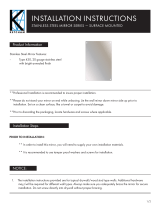
Mirror Arrangement:
testing distance when the room does not permit a direct-throw arrangement. Typically, your ClearChart
4 will be positioned higher than patient eye level so that the examiner will not interfere with the patient’s
view of the ClearChart 4. Arrange the ClearChart 4 and mirror so that the ClearChart 4 can be seen by
the patient through the mirror.
1. Find an appropriate spot on the wall that will support the ClearChart 4, which will hang from the
VESA compliant Mounting Bracket. Ensure that the refraction distance meets the requirements
for either Direct Throw or Mirror Arrangement.
2. Level the supplied Wall Mount Bracket and mark the holes on the wall. The mount should be
installed in solid wood stud, brick or concrete wall.
3. Hang the ClearChart 4 by lining-up the holes on the back of the device with the four holes on the
mounting bracket. Secure the ClearChart 4 to the mounting bracket with the 4 screws provided.
13795-101 Rev. F
9
(continued)

13795-101 Rev. F
10
Articulating Wall Mount
WARNING: BE SURE TO READ THE WALL MOUNT INSTRUCTIONS THOROUGHLY AND THAT YOU
FULLY UNDERSTAND ALL THE INSTRUCTIONS AND WARNINGS BEFORE ATTEMPTING TO BEGIN
YOUR INSTALLATION.
WARNING: THIS PRODUCT SHOULD ONLY BE INSTALLED BY SOMEONE WHO HAS A BASIC KNOWL-
EDGE OF BUILDING CONSTRUCTION, INSTALLATIONS AND FULLY UNDERSTANDS THESE INSTRUC-
TIONS.
WARNING: MAKE SURE THAT THE SUPPORTING SURFACE WILL SAFELY SUPPORT THE COMBINES
LOAD OF THE MOUNT, THE DISPLAY AND ALL ATTACHED HARDWARE AND COMPONENTS.
WARNING: MAKE SURE THE MOUNTING SURFACE WILL SAFELY SUPPORT THE COMBINED LOAD OF
THE EQUIPMENT AND ALL ATTACHED HARDWARE AND COMPONENTS.
WARNING: THIS BRACKET WILL ONLY SUPPORT FLAT PANEL DISPLAYS. THE MAXIMUM LOAD CA-
PACITY IS 30 POUNDS.
WARNING: IF MOUNTING TO A WALL OF WOOD STUD CONSTRUCTION, BE SURE THAT MOUNTING
BOLTS ARE ANCHORED TO THE CENTER OF THE STUDS.
WARNING: ALWAYS HAVE SOMEONE ASSIST YOU TO LIFT AND POSITION YOUR EQUIPMENT.
WARNING: TIGHTEN SCREWS AND BOLTS FIRMLY, BUT DO NOT OVER TIGHTEN. OVER TIGHTENING
CAN DAMAGE THE ITEMS AND GREATLY REDUCE THEIR ABILITY TO HOLD. PLEASE REFER TO SUG-
GESTED TORQUE VALUES WHERE APPLICABLE.
Parts Included in the Articulating Wall Mount
Make sure you have received all of the parts in the component checklist before installing the mount.
Refer to Figure SU-04. If any parts are missing or faulty contact Reichert for a replacement. (Con-
tact information is located on the back page of this User’s Guide.)
Figure SU- 04 Wall Mount and Hardware
Screws
(3 Pc)
Wall Anchors
(3 Pc)
Wall
Mount
Thumb Screws
(4 Pc)
(continued)

13795-101 Rev. F
11
Articulating Wall Mount (continued)
Wood Stud Wall Mounting
Hardware provided is for attaching the mount in standard thick-
ness drywall or plaster into wood studs. Installers are respon-
sible to provide hardware for other types of mounting situations.
1. Remove the part of the mount that attaches to the back of
the ClearChart 4 from the part of the mount that attaches
to the wall by sliding that part up and removing it. Refer to
Figure SU-05.
2. Make sure that mounting screws are anchored into the Cen-
ter of the studs. Use a stud finder to locate the Center of the
studs. Use of an edge to edge stud finder is highly recom-
mended. Use a level to draw a vertical line down the center
of the stud. Refer to Figure SU-06.
3. Place the wall plate on the wall as a template and mark the
center of the three mounting holes. Make sure the mounting
holes are on the stud center line. Refer to Figure SU-06.
4. Drill three 3 mm (1/8 in.) diameter holes 50 mm (2 in.) deep.
Make sure that the wall plate is level, and secure it using the
screws. Level the plate then tighten all fasteners. Refer to
Figure SU-07.
Figure SU- 06 Mark Screw Holes
Level
Stud
Mark 3
Screw
Holes
Install 3
Screws
No Wall
Anchors
Needed
Figure SU- 07 Mount to a Wood Stud
(continued)
This Part
Mounts
To Wall
Figure SU- 05 Disconnect Two
Parts of Mount
Slide Up to
Remove
This Part
Mounts To
ClearChart 4

13795-101 Rev. F
12
(continued)
Articulating Wall Mount (continued)
Drywall, Plaster, Solid Brick and Concrete Block Mounting
WARNING: WHEN INSTALLING WALL MOUNTS ON CINDER BLOCK, VERIFY THAT YOU HAVE A MINI-
MUM OF 35 MM (1 3/8 IN.) OF ACTUAL CONCRETE THICKNESS IN THE HOLE TO BE USED FOR THE
CONCRETE ANCHORS. DO NOT DRILL INTO THE MORTAR JOINTS! BE SURE TO MOUNT IN A SOLID
PART OF THE BLOCK, GENERALLY 25 MM (1 IN.) MINIMUM FROM THE SIDE OF THE BLOCK. CINDER
BLOCK MUST MEET ASTM C-90 SPECIFICATIONS. IT IS SUGGESTED USING AN ELECTRIC DRILL ON
THE SLOW SETTING TO DRILL THE HOLE INSTEAD OF A HAMMER DRILL TO AVOID BREAKING OUT
THE BACK OF THE HOLE WHEN ENTERING A VOID OR CAVITY. CONCRETE MUST BE 2000 PSI DEN-
SITY MINIMUM. LIGHTER DENSITY CONCRETE MAY NOT HOLD CONCRETE ANCHOR.
The installer must verify that the supporting surface will safely support the combined load of the
equipment and all attached hardware and components.
1. Remove the part of the mount that attaches to
the back of the ClearChart 4 from the part of the
mount that attaches to the wall by sliding that part
up and removing it. Refer to Figure SU-05.
2. Use the Wall Plate as a template to mark the
mounting holes on the wall. Refer to Figure SU-09.
3. Drill two 6 mm (1/4 in.) diameter holes 70 mm (2
in.) in depth.
4. Insert the anchors in the holes so they are flush
with the wall. Refer to Figure SU-08.
Note: Ensure the correct anchors are being used.
Anchors provided are for drywall and plaster
mounting ONLY. For mounting in brick or con-
crete blocks, obtain the proper wall anchors.
5. Place the Wall Plate over the anchors and secure it
with the screws. Refer to Figures SU-08 and SU-09.
6. Make sure the wall plate is level, then tighten the screws.
Anchors
Figure SU-09 Installation with Wall Anchors
Level
Mark 3
Screw
Holes
Screws
Figure SU-08 Wall Anchor Installation
1
2
3
Drill Holes &
Insert Anchors
Wall
Surface
Place Wall Plate
Over Anchor
and Secure
With Screws
Tighten All
Fasteners

13795-101 Rev. F
13
(continued)
Articulating Wall Mount (continued)
Attaching the ClearChart 4 to the Mount
1. Align the half of the mount that was removed in the previous steps to the back of the ClearChart
4, aligning it with the screw holes. Refer to Figure SU-10.
Figure SU-10 Align Holes and Attach Mount
Screw
Holes
Align Outer
Holes
Install
Thumb Screws
Note: There is a slot on the back of the mount. Be sure this slot remains in the vertical position when
aligning the mount to the back of the ClearChart 4. Refer to Figure SU-11.
2. Using the Thumb Screws, secure the mount to the ClearChart 4 by
hand-tightening the 4 screws into the outer screw holes on the back of
the case of the ClearChart 4. Refer to Figure SU-10.
Note: The screws must make at least three full turns into the mounting hole
3. Slide the ClearChart 4 onto the mounting bracket that is already attached
to the wall, so the square slides into the slot on the mount. Refer to
Figure SU-12.
4. Secure the mount by tightening the two small flathead screws on either
side of the mount where the ClearChart 4 attached to the wall mount.
Refer to Figure SU-13.
Figure SU-11 Align
Slot Vertically
Figure SU-12 Attach ClearChart 4 to Wall Mount
Slide
Down
Side
View
Attached to Wall
Back of ClearChart 4
Attached
to Wall
Attached to
ClearChart 4
Securing
Screw
Figure SU-13 Securing Screws

13795-101 Rev. F
14
Articulating Wall Mount (continued)
Pitching Angle Adjustment
Adjust the ClearChart 4 to the desired angle. The mount can be adjusted upward and downward 15º
and can be swiveled from side to side 120º. Refer to Figure SU-14.
Figure SU-14 Angling Bracket
120°
15º
Maintenance
Once you have mounted the bracket and the ClearChart 4, check that they are secure and safe to
use. Check that the screws are fixed well every two months. If you have any concerns about the
installation contact Reichert Technical Service. Contact information can be found on the back cover
of this User’s Guide.
(continued)

13795-101 Rev. F
15
Old Style ClearChart Wall Mount Bracket
If the old style ClearChart Wall Mount Bracket is preferred, or if it is already installed on the wall, the
optional Wall Mount Bracket Adaptor (P/N 13775-014) can be used to mount the new ClearChart 4 to
the older ClearChart Wall Mount Bracket.
Line up the metal plate so that the tabs are oriented up, and the screw holes line up with the
ClearChart 4 screw holes. Secure the plate with the 4 Thumb Screws. Refer to Figure SU-15.
Figure SU-15 Align Holes and Attach
Screw
Holes
Attach
Plate
Installing the ClearChart Wall Mount Bracket
1. Find an appropriate spot on the wall that will support the ClearChart 4, which will hang from the
Wall Mount Bracket attached to the wall inserts included with the accessories. Ensure that the
refraction distance meets the requirements for either Direct-throw or Mirror Arrangement.
2. Level the supplied Wall Mount Bracket (P/N 13750-008) with the metal tabs facing up and out on
your wall and mark the holes on the wall.
3. Using the supplied Drywall Fasteners, place the tip of each fastener on the marked hole and using a
hammer tap the insert into the wall as far as the threads on the insert. Using a phillips-head screw-
CAUTION: DO NOT OVER DRIVE THE INSERTS INTO THE WALL.
4. Place the Wall Mount Bracket on the wall, and screw the supplied screws into the Drywall Fasteners.
Refer to Figure SU-17.
5. Hang the ClearChart 4 by lining-up the holes on the back of the adaptor plate with the metal tabs of
the Wall Mount Bracket and hang the unit from these tabs.
(continued)
Figure SU-16 Drywall Fastener
Figure SU-17 Mounting the Wall Bracket

13795-101 Rev. F
16
Application of Input Power
1. Using the provided power cord, insert the female end into the power input receptacle located at the
bottom of the instrument. Refer to Figure SU-18.
2. Plug the male end of the power cord into a wall outlet of the appropriate voltage. Input voltage must
not exceed the range listed in the Specifications section of this manual.
3. Set the ON / OFF switch to ON ( I ).
Figure SU-18 Power Cord and On/O Switch
Power
Cord
Switch
Disconnection of Input Power
At any time, the power switch can be set to OFF. The unit does not have a power down sequence.
To terminate operation of the ClearChart 4, press the ON / OFF switch to the OFF position (O).
Note: If the ClearChart 4 is intended to be OFF for an extended period of time, the ClearChart 4
can be disconnected from power by detaching the power cord from the receptacle.
Note:
at the end of the day.
(continued)

13795-101 Rev. F
17
Communication Ports
The ClearChart 4 has a 9 pin female serial port on the bottom of the instrument housing that can
be used for either hard-wired or wireless connection to a Reichert digital refraction system. The
ClearChart 4 also has two exposed USB ports to power a wireless serial adapter, connect a USB Blue-
tooth
®
adaptor, or to upload photos and videos (ClearChart 4X only). Refer to Figure SU-19.
Figure SU-19 Ports
Serial Port
2 USB
Ports
Connection with a Reichert Digital Refraction System
The ClearChart 4 can directly connect to a Reichert digital refraction system, using a cable
or wirelessly connected using a Bluetooth serial adapter. Wired communication between the
ClearChart 4 and the digital refraction system requires connection of a cable between the serial port
on the ClearChart 4 and the digital refraction system.
Bluetooth Connection
Wireless communication between the ClearChart 4 and a Reichert digital refraction system requires
connection of a Bluetooth device. Either a USB Bluetooth adapter (PN 13779) can be used, or a
Bluetooth serial adaptor (PN 16251) powered by the USB port or with a separate AC adapter.
If using the USB Bluetooth adaptor (PN 13779), install the Bluetooth into one of the USB ports on the
bottom of the ClearChart 4. Refer to Figure SU-20.
Figure SU-20 Install USB Bluetooth
USB Bluetooth
Adaptor
-continued-
(continued)

13795-101 Rev. F
18
Connection with a Reichert Digital Refraction System (continued)
Bluetooth Connection (continued)
If using the Bluetooth serial adaptor (PN 16251), connect the Bluetooth Dongle to the end of the Null
Modem Cable. Refer to Figure SU-21.
Figure SU-21 Connect Dongle to Cable
Bluetooth Dongle
Null Modem
Cable
Connect the other end of the Null Modem Cable to the port on the bottom of the ClearChart 4. If
using the USB Power Adaptor, connect it to the USB port on the bottom. Refer to Figure SU-22.
Figure SU-22 Connect USB Power and Null Modem Cable
Null
Modem
Cable
USB Power
Adaptor
If using an A/C power adaptor, plug the adaptor to a properly volted outlet. Connect the power cord
to the Bluetooth Dongle. Refer to Figure SU-23.
Figure SU-23 Connect Dongle to Power
Bluetooth Dongle
Power Cord
(continued)

13795-101 Rev. F
19
(continued)
Remote Control Power
1. Remove the back of the remote control by sliding it in the direction of the arrow.
2. Put in two AAA batteries in the position shown on the remote control.
Remote Control Layout
The remote control will operate all the test charts on your ClearChart 4. The image and chart below
indicate the functions of each button. The numbered buttons in the image below represent the
optotype progression.
EDU – Educational Images or other imported images
MOVIE – Children’s Video or other imported videos
NUMBERS – Size of Optotypes in Decimal/LogMAR,
Standard/Snellen, or Decimal/Linear
RED/GREEN – Red/Green Filters for Optotypes
RANDOM – Randomize Optotypes
UP ARROW – Function depends on test chart
RIGHT ARROW – Function depends on test chart
LEFT ARROW – Function depends on test chart
DOWN ARROW – Function depends on test chart
MENU – Menu options and settings
SAVE – Save menu item changes
OPTO – Change Optotype Selection
CONT – Contrast Sensitivity Testing (Sine Wave Grating)
LIGHT – Change Background Illumination
SIZE – Optotype size displayed on screen
ALT OPT – Change to Alternative Optotype Selection
MAX – Increase Contrast
MIN – Decrease Contrast
XCYL – Cross Cylinder Test Chart
ASTIG – Astigmatism Test Charts
T – Astigmatic T Test Chart
FIX – Fixation Test
HDISP – Horizontal Disparity Test Chart
VDISP – Vertical Disparity Test Chart
DARK – Dark Screen
WORTH – Worth 4 Dot Test
CBAR – Crowding Bars
SUPP – Suppression Tests
ANIM – Animate Current Optotype
Display multiple lines of optotypes, same size
Display multiple lines of optotypes, descending size
Display a vertical line of optotypes
Display a single optotype

13795-101 Rev. F
20
Conguring the ClearChart 4
Press the ON/OFF switch located on the bottom of the instrument. The ClearChart 4 will boot-up.
When the ClearChart 4 welcome screen appears, press the MENU button on the remote to enter the
ROOM
Using the LEFT/RIGHT arrows on your remote, select DIRECT THROW or MIRRORED based on the
UNITS
Using the LEFT/RIGHT arrows on your remote, select METRIC or ENGLISH units based on which
Direct Throw
ClearChart
Patient
Patient to Screen Distance
Mirror Set Up
ClearChart
Patient
Patient to Mirror Distance
Mirror
ClearChart to Mirror Distance
(continued)
/