
Studer Innotec SA 2014 V 1.2.1
4O9P
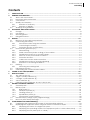
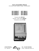
VarioString
MPPT solar charge controller
User manual
Accessories:
Remote control……………………………………. RCC-02/03
Temperature sensor…....…………………………. BTS-01
External auxiliary relay module...………………. ARM-02
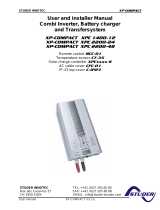
VarioString
VS - 120
48V- 120A


Studer Innotec SA
VarioString
User manual V 1.2.1 3
Contents
1 INTRODUCTION ...................................................................................................................................... 5
2 GENERAL INFORMATION ....................................................................................................................... 5
2.1 About this user manual ....................................................................................................................... 5
2.2 Important safety instructions .............................................................................................................. 6
2.3 Conventions .......................................................................................................................................... 6
2.4 Quality and warranty .......................................................................................................................... 7
2.4.1 Exclusion of warranty .................................................................................................................. 7
2.4.2 Exclusion of liability ...................................................................................................................... 7
2.5 Warnings and guidelines .................................................................................................................... 8
3 MOUNTING AND INSTALLATION ........................................................................................................... 8
3.1 Storage .................................................................................................................................................. 8
3.2 Unpacking ............................................................................................................................................. 8
3.3 Mounting place.................................................................................................................................... 9
3.4 Fixing/Dimensions ................................................................................................................................. 9
4 WIRING ................................................................................................................................................. 10
4.1 Elements of the cable compartment ............................................................................................ 10
4.2 Connecting the battery ................................................................................................................... 12
4.2.1 Precautions when using the batteries ................................................................................... 12
4.2.2 Connecting the battery ........................................................................................................... 13
4.2.3 Protection device of the battery ........................................................................................... 13
4.3 Photovoltaic generator (PV) ........................................................................................................... 14
4.3.1 Dimensioning .............................................................................................................................. 14
4.3.2 Serial connection (chain or string) of PV modules ............................................................. 14
4.3.3 Parallel connection of PV module strings ............................................................................. 14
4.3.4 Safe use of the photovoltaic modules .................................................................................. 15
4.3.5 Protection devices .................................................................................................................... 15
4.3.6 Cable cross-section and connection ................................................................................... 15
4.3.7 Parallel connection of several VarioString ........................................................................... 15
4.3.8 Extension of an existing installation ........................................................................................ 16
4.4 Earthing ................................................................................................................................................ 16
4.4.1 Detecting an earthing fault .................................................................................................... 17
4.5 Lightning protection .......................................................................................................................... 17
4.6 Connecting the communication cables ...................................................................................... 17
5 POWER-UP OF THE EQUIPMENT ........................................................................................................... 18
6 DISPLAY SYSTEM ................................................................................................................................... 19
6.1 The “SET” button (4) ........................................................................................................................... 19
6.2 “Night” standby indicator (1) .......................................................................................................... 19
6.3 “Charge” cycle indicator (2) .......................................................................................................... 19
6.4 “Error” indicator (3) ............................................................................................................................ 20
6.5 Charging current Indicator (5)-(6)-(7)-(8)-(9)-(10) ....................................................................... 20
7 BATTERY CHARGING PROCESS ........................................................................................................... 21
7.1 General points .................................................................................................................................... 21
7.2 Battery cycle ....................................................................................................................................... 21
7.2.1 Bulk phase (1) ............................................................................................................................. 21
7.2.2 Absorption phase (2) ................................................................................................................ 21
7.2.3 Floating phase (4) ..................................................................................................................... 21
7.2.4 Equalization phase (3) .............................................................................................................. 21
7.2.5 Temperature compensation ................................................................................................... 22
7.3 Default battery charge cycle (original settings) ......................................................................... 22
7.4 Recovery after deep discharge ..................................................................................................... 22
8 CONFIGURING THE VARIOSTRING(S) ................................................................................................. 23
8.1 Configuring the equipment by means of the internal DIP switches ........................................ 23
8.2 Displaying the equipment status using the remote control RCC-02/03 .................................. 25
8.2.1 Displaying the status of a single unit system ........................................................................ 25
8.2.2 Displaying the operating mode of the equipment (Info n° 15013,15014,15015) .......... 27
8.2.3 Displaying security errors (Info n° 15049) ............................................................................... 27

Studer Innotec SA
VarioString
4 V 1.2.1 User manual
8.2.4 Displaying the values of a multi-unit system ........................................................................ 28
8.2.5 Displaying messages and event history ................................................................................ 28
8.3 Configuring the VarioString using the remote control RCC-02/03 ........................................... 28
8.3.1 The real time clock .................................................................................................................... 29
8.4 Description of the VarioString parameters .................................................................................... 29
8.4.1 Convention ................................................................................................................................. 29
8.4.2 Parameter access level ........................................................................................................... 29
8.4.3 Organisation of the VarioString configuration menu ......................................................... 30
8.4.4 Basic settings {14000} ................................................................................................................ 31
8.4.5 Battery management and cycle {14003} ............................................................................. 32
8.4.6 System {14037} ........................................................................................................................... 35
8.4.7 Auxiliary contacts 1 {14070} and 2 {14122} ........................................................................... 37
9 ACCESSORIES ...................................................................................................................................... 40
9.1 Remote control and programming centre RCC-02/03 .............................................................. 40
9.2 Temperature sensor BTS-01 ............................................................................................................... 41
9.2.1 Connecting the temperature sensor (BTS-01) ..................................................................... 42
9.3 Auxiliary relay module ARM-02 ........................................................................................................ 42
9.4 Parallel connection cable ............................................................................................................... 42
10 EQUIPMENTS COMPATIBLE WITH THE VARIOSTRING ......................................................................... 43
10.1 Xtender inverter/chargers ................................................................................................................ 43
10.2 Battery status processor BSP- 500/1200 .......................................................................................... 43
10.3 Communication module Xcom-232i .............................................................................................. 43
10.4 Communication sets Xcom-LAN/-GSM ......................................................................................... 43
11 WIRING EXAMPLES .............................................................................................................................. 44
11.1 VarioString + RCC-02 ......................................................................................................................... 44
11.2 Comments on the wiring examples 11.1 ....................................................................................... 44
12 MAINTENANCE OF THE INSTALLATION ............................................................................................... 45
13 PRODUCT RECYCLING ......................................................................................................................... 45
14 EC DECLARATION OF CONFORMITY .................................................................................................. 45
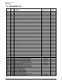
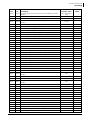
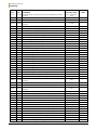
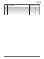
15 PARAMETER LIST ................................................................................................................................... 46
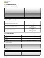
16 TECHNICAL DATA ................................................................................................................................ 50
16.1 General specifications ...................................................................................................................... 50
16.2 Input (PV generator) ......................................................................................................................... 50
16.3 Output (battery) ................................................................................................................................. 50
16.4 Environment ........................................................................................................................................ 50
16.5 Protection ............................................................................................................................................ 50
16.6 Communication ................................................................................................................................. 51
16.7 Compliance ........................................................................................................................................ 51
17 INDEX OF PARAMETERS ....................................................................................................................... 52

Studer Innotec SA
VarioString
User manual V 1.2.1 5
1 INTRODUCTION
Congratulations! You are about to install and use a device from the VarioString range. You have
chosen high-tech equipment that will play a central role in the energy production of your solar
electrical installation. The VarioString has been designed to work as a solar battery charger; its
advanced and completely configurable functionalities will guarantee a perfect functioning of your
energy system.
When the VarioString is connected to batteries and photovoltaic panels, it automatically recharges
batteries in an optimum way with all the available solar power. The VarioString can be connected to
two strings of PV modules in different configurations (series, parallel, or independent). This
configuration flexibility allows the user to optimise their installation. The accuracy of the Maximum
Power Point Tracking (MPPT) algorithm, the high output and low internal consumption ensure an
optimal valorisation of the energy produced by the PV modules.
The charge profile may be set freely according to the battery type or the operation mode. The
charging voltage is corrected depending on the temperature thanks to the optional external sensor
BTS-01.
The control, display and programming unit RCC-02/03 (optional) allows an optimal setup of the
system and guarantees the user a permanent control over all important parameters for the
installation with a clear display interface. Moreover, it allows recording the system data in order to
analyse later its functioning (data logging).
The parallel operation of several chargers is possible and offers modularity and flexibility enabling an
optimum dimensioning of your system according to your energy requirements.
The VarioString operates as an independent device but is also designed to be included into a Studer
energy system together with the Xtender inverters/chargers, the BSP battery monitor, the control,
display and programming unit RCC-02/03, the communication modules Xcom-232i and Xcom-
LAN/GSM. Working together, these different devices have a synchronised behaviour for a better
management of the battery and of the solar resource.
Please read this manual carefully to ensure the perfect start up and operation of your system. It
contains all necessary information regarding the operation of the VarioString charger. The installation
of such a system requires special expertise and may only be carried out by qualified personnel
familiar with the local standards in force.
2 GENERAL INFORMATION
2.1 ABOUT THIS USER MANUAL
This manual contains necessary information and procedures to install, configure, use and
troubleshoot the VarioString solar charge controllers. It does not contain information about
photovoltaic modules (PV) or batteries of various brands that can be connected. For this kind of
information, please refer to the instructions of each specific manufacturer.
It covers the following models and accessories:
MPPT solar charge controller : VarioString VS-120
Temperature sensor : BTS-01
External auxiliary relay module : ARM-02
This manual is an integral part of the equipment and must be available for the operator
and/or the installer at all times. Always keep it close to the installation.

Studer Innotec SA
VarioString
6 V 1.2.1 User manual
2.2 IMPORTANT SAFETY INSTRUCTIONS
This manual contains important safety instructions. Read carefully the safety and operation
instructions before using the VarioString. Take into consideration all warnings mentioned both on the
equipment and in this manual, strictly following all instructions regarding its operation and use.
This user manual is intended to serve as a guideline for the safe and efficient use of the VarioString.
Anyone who installs or uses a VarioString can completely rely on this user manual and is bound to
observe all the safety instructions and indications here in.
The installation and commissioning of the VarioString must be entrusted to qualified personnel. The
installation and use must comply with the local safety instructions and standards in force in the
country.
2.3 CONVENTIONS
This symbol is used to indicate safety instructions which, if not followed, could result in serious
personal injury or death to the operator or the user.
This symbol is used to indicate a general danger for the user and/or a risk of material
damage and/or the cancellation of the guarantee.
This symbol is used to indicate a procedure or function that is important for a safe and
correct use of the equipment. Failure to respect these instructions may lead to the
cancellation of the guarantee or to a non-compliant installation.
This symbol placed on the product indicates that its surfaces may reach temperatures
higher than 60°C.
This symbol placed on the product indicates that its use must follow the instructions in the
user’s manual.
In general, values important for the operation of the equipment (for example: battery voltage during
absorption) are not mentioned and the parameter number is indicated in the following format:
{xxxxx}. The value of the parameter can be found in the table chap. 15.
In most cases, these values can be modified with the remote control RCC-02/03 (see chap. 9.1).
The parameter table available at the end of this manual (chapter 15) must be kept updated
in case the parameters are modified by the operator or the installer.
If an authorised person modifies a parameter not included in the list (advanced
parameters), the number of the modified parameter(s), the specifications of the
parameter(s) and the new value set are to be indicated at the end of the table.
All values that are not followed by a parameter number may not be modified.
All digits and letters in brackets or in square brackets in the text of this manual refer to items
represented in illustrations with a circle.

Studer Innotec SA
VarioString
User manual V 1.2.1 7
2.4 QUALITY AND WARRANTY
During production and assembly of the VarioString, each unit undergoes several checks and tests
which strictly comply with established procedures. The manufacturing, assembling and testing of
each VarioString are completely carried out in our factory in Sion (CH). The equipment warranty
depends upon the strict application of the instructions in this manual.
The VarioString MPPT solar charge controller has a 5-year warranty (starting from the date of
production against material and manufacturing faults). A defective product will either be repaired
or replaced at the discretion of Studer Innotec.
2.4.1 Exclusion of warranty
No warranty claims will be accepted for damages resulting from handling, use or treatment that are
not explicitly mentioned in this manual. In particular, damages arising from the following causes are
excluded from the warranty:
Voltage higher than 600V across PV terminals (independent or parallel configuration) or
higher than 900V (series configuration).
Battery reversed polarity across PV input terminals.
Accidental presence of liquids in the equipment or oxidation due to condensation.
Damage resulting from falls, mechanical shocks or permanent or excessive vibrations.
Modifications carried out without the explicit authorisation of Studer Innotec.
Nuts or screws that have not been tightened sufficiently during the installation or
maintenance.
Damage due to atmospheric surge voltage (lightning).
Damage due to inappropriate transportation or packaging.
Disappearance of original identification marks.
Never take off or damage the rating plate showing the serial number. It enables to check
and follow-up the data specific to each equipment and is vital for any warranty claim.
2.4.2 Exclusion of liability
The installation, commissioning, use, maintenance and servicing of the VarioString cannot be subject
of monitoring by Studer Innotec. Therefore, we disclaim all responsibility and liability for damage,
costs or losses resulting from an installation that does not comply with the instructions, a faulty
operation or inadequate maintenance. The use of Studer Innotec equipment is in any case under
the responsibility of the customer.
This equipment is neither designed nor guaranteed to supply installations used for vital medical care
nor any other critical installation entailing potential risks of important damage to people or to the
environment.
We assume no responsibility for the infringement of patent rights or other third parties rights resulting
from the use of the MPPT solar charge controller VarioString.
Studer Innotec reserves the right to make any modifications to the product without prior notification.
Studer Innotec is not liable for incidental, direct or indirect damages of any kind, including any profit
loss, revenue loss or damages caused to equipment or goods due to defective equipment.

Studer Innotec SA
VarioString
8 V 1.2.1 User manual
2.5 WARNINGS AND GUIDELINES
The installation and commissioning of the VarioString must be entrusted to skilled and qualified
personnel perfectly aware of the safety precautions and local rules in force. All elements connected
to the VarioString must comply with the laws and regulations in force.
HIGH-VOLTAGE DC INSIDE THE CHARGE REGULATOR: DANGER OF DEATH
When the VarioString is in operation it generates voltages that can be potentially lethal (up
to 1000Vdc). Any work on or close to the installation must only be carried out by thoroughly
trained and qualified personnel. Do not try to carry out ordinary maintenance on this
product yourself.
While working on the electrical installation, it is important to make sure that the source of
DC voltage coming from the battery as well as the source of DC voltage coming from the
photovoltaic generator, have been disconnected from the electrical installation.
Even when the VarioString has been disconnected from the power sources, a potentially
dangerous voltage may remain at the terminals. To eliminate this you have to wait for at least
5 minutes in order to allow the electronics to discharge. The task can then be carried out safely.
No person is authorized to proceed with any change, modification or repair of the equipment without
prior written authorisation from Studer Innotec. Only original parts should be used in authorised
modifications or replacements.
Respect the maximum rated specifications of the equipment indicated on the type label.
The VarioString can be installed at altitudes up to 3000m. For installations at higher
altitudes, please contact Studer Innotec SA. The VarioString is in overvoltage category
II, in accordance with the norm IEC/EN 62109-1:2010 that considers all solar generators
as being in overvoltage category II.
3 MOUNTING AND INSTALLATION
The wiring and connection of the installation must be carried out only by perfectly qualified
personnel. The installation material such as cables, connectors, distribution boxes, fuses,
etc., must be appropriate and comply with the laws and regulations in force for the
application in question.
3.1 STORAGE
The equipment must be stored in a dry environment at an ambient temperature between -20°C and
60°C. Place the equipment at its mounting place at least 24 hours before commissioning in order to
avoid thermal shocks and condensation problems.
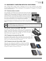
3.2 UNPACKING
When unpacking, check that the VarioString has not been damaged during transportation and that
all accessories listed below are present. Any fault must be immediately reported to the product
distributor or the contact mentioned at the back of this manual.
Carefully check the packaging as well as the VarioString.
Contents in the VarioString box:
VarioString
Installation and operation manual
Cable-glands for the battery cables
Two pairs of solar cable connectors

Studer Innotec SA
VarioString
User manual V 1.2.1 9
3.3 MOUNTING PLACE
The mounting place for the VarioString is particularly important and must fulfil the following criteria:
Indoors (IP20).
Protected from water and dust in a location without condensation.
Protected from any unauthorized person.
In a place where the relative humidity does not exceed 95%
In a place where the ambient temperature is between -20 and 55°C
In mobile applications, it is important to select a mounting place that ensures no vibration.
Protected from direct solar radiation or heat sources.
It should not be mounted directly above the battery or in a cabinet with the battery
The ventilation vents should be clear at all times and at least 20 cm from all obstacles that
could alter the ventilation of the device.
Given the norm IEC/EN 62109-1, the degree of pollution in the installation area should be at
maximum PD2.
The support for the VarioString and the environment in which it is contained should not be
flammable.
The presence of a heat source may significantly reduce its rated power. Similarly, insufficient
ventilation may lead to the overheating of some internal components of the equipment. In this case,
the device will automatically limit its power as long as this abnormal situation persists.
As far as possible, reduce exposure to sudden temperature variation: important heat variation may
create undesired and harmful condensation inside the equipment.
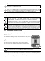
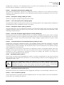
3.4 FIXING/DIMENSIONS
The VarioString is a heavy equipment (~8kg) and must be mounted to a support (wall)
designed to bear such a load. It is imperative to ensure a complete and safe fastening of
the equipment. If simply hung, it may fall down and cause severe damages.
Upper support screw: screw into the wall a 6-8 mm diameter screw without washer until there is 2 mm
between the head of the screw and the wall. Hang the device from the screw. If deemed necessary,
the upper support screw can be fully tightened after hanging the device. In theory this is only
necessary in mobile applications. To access the upper support screw to fully tighten it, remove the
upper plastic grate.
Lower support screws: remove the lower plastic grate which gives access to the cabling
compartment. Carefully fix the device to the support with two screws (6-8 mm in diameter) using the
two mounting holes located at the bottom left and right of the cabling compartment.
The VarioString must be installed vertically. A distance of at least 5cm between the units and/or 20cm
around the equipment is required to guarantee adequate ventilation.
If the VarioString is
installed in a closed
cabinet, it must have a
sufficient ventilation to
guarantee that the
ambient temperature
is kept within the
operating limits of the
VarioString.
In motor vehicles, or
when the support
undergoes significant
vibrations, the
VarioString is to be
mounted on anti-
vibration elements.

Studer Innotec SA
VarioString
10 V 1.2.1 User manual
4 WIRING
The connection of the VarioString charger is an important step of the installation.
It may only be carried out by qualified personnel, aware of the rules and regulations in force.
The installation must always comply with these standards. The cross-sections of the cables
connected to its terminals must comply with local regulations. All cables in use should be
isolated with PVC, TFE, PTFE, FEP, neoprene or polyimide.
Make sure that connections are completely tightened and that each wire is connected at
the right place.
The VarioString is intended to be connected exclusively to a source like a photovoltaic
generator, excluding any other energy source.
It is suitable for charging any type of lead-acid batteries. It is often possible to charge any
other type of battery using proper settings and with the express approval of the battery
supplier.
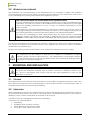
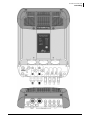
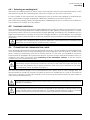
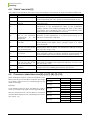
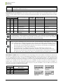
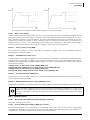
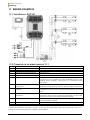
4.1 ELEMENTS OF THE CABLE COMPARTMENT
No.
Description
Comments
1
Terminal to connect the battery positive
pole (M8, 8Nm torque, PG-21 (13-
18mm))
This connection must be done using a protection
and disconnection device if the pole has not
been earthed. For mounting of the internal fuse,
refer to sect. 4.2.2
2
Terminal to connect the battery
negative pole (M8, 8Nm torque, PG-21
(13-18mm))
This connection must be done using a protection
and disconnection device if the pole has not
been earthed.
3
Connector (Sunclix) for negative pole of
solar generator n°2.
The solar generator wiring must be carried out in
compliance with the voltage and current limits
mentioned on the rating plate.
4
Connector (Sunclix) for positive pole of
solar generator n°2.
5
Connector (Sunclix) for negative pole of
solar generator n°1.
6
Connector (Sunclix) for positive pole of
solar generator n°1.
7
Socket for connection of accessories
BTS-01 or ARM-02 (battery temperature
sensor and auxiliary relay module)
Only the mentioned original accessories can be
connected to this connector.
8
Socket for communication cables and
the remote control RCC-02/03.
RJ45 connector used for connecting equipment
of the Xtender family. These connections must be
carried out only with original Studer cables.
9
Termination switch
The switch must be placed in position O (towards
(8)) when both connectors are used.
10
Configuration switches (DIP-switch)
The various possible configurations are described
in sect. 8.1
11
Real-time clock battery
(type CR 2032)
The equipment is fitted with a battery lasting
about 10 years.
The connection compartment of the VarioString must remain permanently closed while the
apparatus is operating.
Before opening, check that all voltage sources (battery and PV) have been disconnected
or switched off and wait for at least 5 minutes before opening the equipment. It is imperative
to close the protection cover on the connection terminals after each servicing.


Studer Innotec SA
VarioString
12 V 1.2.1 User manual
4.2 CONNECTING THE BATTERY
The VarioString is a device which DC (battery) connection is to be connected exclusively to a battery.
Most of the time, lead-acid batteries with liquid (VLA, VRLA) or gelled (GEL) and AGM electrolyte
may be used. It can be easily configured to create charge profiles that are compatible with these
various types of lead-acid batteries.
4.2.1 Precautions when using the batteries
The batteries should only be chosen, dimensioned and installed by qualified personnel, trained in this
specific area. When working with batteries, a second person is required in order to give assistance in
case of problems.
Lead-acid batteries with liquid or gelled electrolyte produce a highly explosive gas during normal
use. Avoid source of sparks or fire in the immediate vicinity of the batteries. The batteries must be
kept in a well-ventilated place and installed so as to avoid accidental short-circuits when
connecting.
Never try to charge frozen batteries.
Sufficient fresh water and soap must be kept close at hand to allow adequate and immediate
washing of the skin or eyes affected by accidental contact with the battery acid.
In the event of accidental contact of the eyes with acid, they must be washed carefully with cold
water for 15 minutes. Then immediately consult a doctor.
The battery acid can be neutralized with baking soda, among other things. A sufficient quantity of
baking soda should be available for this purpose.
Particular care is required when working close to the batteries with metal tools. Tools such as
screwdrivers, open-ended spanners, etc., may cause short circuits. Sparks created by short-circuits
may cause the battery to explode. Therefore these kinds of tools must always have isolated handles
and never be placed on top of a battery.
When working with the batteries, all metal jewellery such as rings, watches with a metal bracelet,
earrings, etc., must be taken off. The current supplied by the batteries during a short circuit is
sufficiently powerful to melt the metal and cause severe burns.
Batteries at the end of their life-cycle should be recycled in accordance with directives from the
responsible local authorities or the battery supplier. The batteries should never be thrown into fire as
they may explode. Under no circumstances should you try to take apart or dismount the battery, as
they contain toxic and polluting materials.
For ungrounded battery systems, always check that they are not inadvertently grounded before
starting working on the batteries.
Always follow carefully the instructions of the battery manufacturer.
If the battery voltage exceeds the value of 68V, the charger turns off and starts again when the
voltage is lower than 64V.
Using the VarioString connected to any other type of DC source without battery is strictly
forbidden and may cause significant damage to the equipment and / or to the source.
The use of other battery types like Ni-Cd, Li-ion or other is possible if the charge profile is
properly programmed, in accordance with the specifications of the battery manufacturer,
in agreement with the battery manufacturer and under the responsibility of the installer.
A battery voltage higher than 80V can cause important damage or destroy the equipment.
Such a voltage applied on equipment connected downstream like Xtender
inverters/chargers or other, can cause important damage or destroy the equipment!

Studer Innotec SA
VarioString
User manual V 1.2.1 13
4.2.2 Connecting the battery
All connection cables as well as the battery cables must be mounted using cable restraints in order
to avoid any pulling on the connection.
Battery cables must also be as short as possible and the cross-section must comply with the
regulations and standards in force. Tighten the clamps on the “Battery” inputs sufficiently.
Lead batteries are usually available in 2V, 6V or 12V blocks. In most cases, in order to get the correct
operating voltage for using the VarioString, several batteries must be connected in series. The
capacity of the batteries can be increased using a parallel connection of several battery strings.
Some battery manufacturers limit the use or advice against parallel connection of battery strings.
Strictly conform to the manufacturer's instructions of use.
4.2.3 Protection device of the battery
The battery cables must be as short as possible. The recommended cable cross-section is 50mm2
and the protection devices (battery side) must be 125A. The protection device must be installed as
close as possible to the battery. The recommended cross-section of battery cable is valid for lengths
up to 3m. Beyond this length, it is recommended to oversize the section of the battery cables.
Any other sources or loads existing on the battery must be connected using their own protection
devices. Never connect them to the protection device(s) of the VarioString.
Each VarioString is connected directly to the battery using its own protective device. All
other consumers or sources are connected directly to the battery through their own
protective device.
In multi-unit systems (connected to the same communication bus), all VarioStrings must be
connected to the same battery bank.
An annual check of all the connection tightness is recommended. In mobile installations,
the connection tightness should be checked more often.
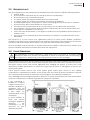
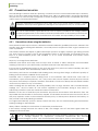
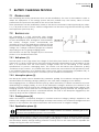
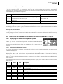
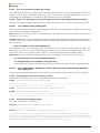
Battery cables must always be protected by one of the following measures:
Have a protection and disconnection device (fuse, circuit breaker) on the pole not
connected to earth.
The protection device must be rated according to the cable cross-section but must not
exceed 1.25 x VarioString maximum current. It will be mounted as close as possible to the
battery.
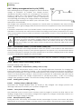
a = M10 cable lug!!
b = bolt M8x30
c = washer
d = ceramic washer
e = fusible

Studer Innotec SA
VarioString
14 V 1.2.1 User manual
4.3 PHOTOVOLTAIC GENERATOR (PV)
The VarioString may accept the following maximum input voltages:
600 V max for independent and parallel cabling
900 V max for series cabling
4.3.1 Dimensioning
The solar generator is dimensioned to cover an important part or the entire power requirement of the
system. Once the power has been decided upon, it will be distributed among one or more solar
charge regulators, wisely combining the modules among them. These combinations in series and in
parallel must be carried out according to the voltage and current limits of the VarioString solar
charge controller.
4.3.2 Serial connection (chain or string) of PV modules
To get the optimum voltage, the PV modules shall be connected in series to form a string with the
desired voltage.
When using the two entries in series, the + terminal of the PV1 entry (6) should be connected to the
+ pole of the PV generator. The – terminal of the PV2 entry (3) should be connected to the – pole of
the PV generator and a bridge should be made between the entries (4) and (5).
The open-circuit voltage of the string must be lower than 600V under any temperature and irradiation
conditions. A 10 to 20% margin is recommended in order to cover these unknowns. When the two
inputs are used in series, the maximum open-circuit voltage should not surpass 900V.
To establish the maximum numbers of the PV modules connected in series in the same string, use the
following formula: 600V/(Uoc*1.1). (Example: 600/(22*1.1)=24.79). The result must be rounded down
(i.e. 24 modules - of 22 Voc - in series for the above example).
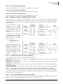
The table below gives an idea of the possible arrangements for common PV modules according to
the number of cells or their type:
36 cell
module
Voc < 23V
60 cell
module
Voc < 37 V
72 cell
module
Voc < 45V
Thin film
module
Voc < 110V
max.
max.
max.
--
23
14
12
4
For independent or parallel
inputs
35
22
18
8
For the two inputs in series
Beware of the PV module temperature! The above values are for modules under standard test
condition (STC).
4.3.3 Parallel connection of PV module strings
To get the required charging power, 2 or more strings can be connected in parallel. Each string
connected in parallel shall be composed of the same number of modules of the same type.
When using the two entries in parallel (up to 26A) it is necessary to physically connect the two
negative terminals (3) and (5) as well as the two positive terminals (4) and (6).
The number of strings connected in parallel depends on the power of each module. The sum of the
power of all the panels connected to a VarioString should not exceed the power that the VarioString
can charge.
The number of strings to be connected in parallel must not exceed the maximum power (see table
below) divided by the power of a string and rounded down to the nearest whole number.
For example, with 12 modules of 110W in series connected to one of the independent inputs:
3500/1320=2.65 => 2 strings (2640W) can be connected in parallel.
The whole solar system must be installed according to protection class II.

Studer Innotec SA
VarioString
User manual V 1.2.1 15
If both VarioString inputs are connected in parallel, for the strings of 12
modules in series mentioned above, 5 strings could be connected in
parallel (7000/1320=5.3 =>5).
The PV generator can be over-dimensioned in order to get the required
charging power even when solar irradiation is lower. In this case, a part
of the solar energy will be lost when the solar irradiation is higher
because the VarioString will reach its current limit and curtail power output.
4.3.3.1 Maximum current of the solar generator
The maximum current of the solar generator (sum of the short-circuit currents for all the strings
connected in parallel) is 26A (13A per input).
In any case, the VarioString will limit the charging current (battery) to its rated current of 120A.
4.3.4 Safe use of the photovoltaic modules
The VarioString is meant for PV generators supplying up to 600Vdc (900Vdc in series). This
voltage is dangerous for human beings.
During the installation or the maintenance of the system, it is imperative to make sure that
no dangerous voltage may surge in the system. The disconnection device must be open
and secured against any accidental reclosing.
4.3.5 Protection devices
Wiring protection devices (fuses, circuit breakers) connecting the PV generator to the VarioString
must be installed in accordance with local standards and regulations in force.
The DIN VDE 0100-712 standard prescribes a switching device on all poles between the PV generator
and the charge regulator. This device must be supplied by the installer.
PV modules are often exposed to stormy weather. It is highly recommended to install lightning
protection (see chap. 4.5).
4.3.6 Cable cross-section and connection
The connection cable cross-section must be chosen according to the short-circuit current of the PV
generator and the local installation rules. The Sunclix type PV connectors do not need any special
tools for mounting. They accept cables between 2.5 and 6mm2 (exterior cross section of 5 to 8mm2).
The length of cable to strip to attach the Sunclix connector is 15mm.
4.3.7 Parallel connection of several VarioString
As many VarioString as necessary can be connected in parallel on the same battery bank according
to the battery capacity. Each will have its own independent solar generator (connected in
independent, parallel or series configuration) and include its own disconnection and protection
device to the battery.
Up to 15 VarioString could be synchronized and interconnected to the same communication bus
(see chap. 4.6) on a single system. Beyond these 15 units, any additional unit will not be
interconnected and thus their battery cycles will work independently.
Solar generators may be of various types and be orientated differently. Each VarioString will adjust
the optimum point of the PV generator independently of the other units connected to the same
battery.
Maximum
recommended power for
the solar generator
Battery
VS-120
48V
3500W/input
The VarioString has a current limit. At any given time, the maximum power of the VarioString
depends on the charging phase voltage of the battery. For example, if the charging phase
is Bulk, and the battery voltage is 50V, the maximum power output is 120A * 50V = 6000VA.
Even if more solar energy is available, the battery charge current will not exceed 120A.
Under no circumstances should PV module inputs of several VarioString be put in parallel.

Studer Innotec SA
VarioString
16 V 1.2.1 User manual
For multi-unit systems, the devices are connected to each other by a communication bus (see chap.
4.6) via the connectors (7) and a cable (ref. CAB-RJ45-8-2) with a maximum length of 5 meters.
As long as they are correctly connected together by the communication cable, the VarioString
automatically synchronize the battery charge cycle.
4.3.8 Extension of an existing installation
In interconnected installations, if the software is compatible, it is possible to extend an existing
installation by adding one or several (up to 15) VarioString units in parallel.
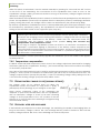
4.4 EARTHING
The VarioString is a Class I protection equipment, its metal case must be
earthed by means of the grounding screw, included for that purpose.
= protective earth (connected to the enclosure of the equipment).
The solar generator (as well as its wiring) must be Class II isolated.
The cross-section of the earthed cable must not be less than 16mm2.
In any case, the protective earth must be connected in accordance with local standards and regulations
in force. The protective earth of the equipment must at least be connected to the earthed ground of all
the Class I equipment after and before the VarioString (equipotential connection). The information, notes,
recommendations and diagrams reported in this manual are subject to local installation rules. The installer
is responsible for the conformity of the installation with the local standards in force.
In multi-unit systems (connected to the same communication bus), all VarioStrings must be
connected to the same battery bank.
When the VarioString units are not synchronized, they must be programmed in the same
way and it is recommended to not activate the periodical equalization function. The
equalization can be manually started or will be done by the synchronized units.
When the devices are in the voltage regulation phase, their currents current may
considerably differ. These differences have no effect at all on the charge quality.
If a VarioString is connected to another compatible device (Xtender, VarioTrack, VarioString,
BSP, RCC, Xcom) with the same communication bus, it is highly recommended to make a
software update of all components in the system in order to guarantee all functionalities.
During the commissioning of the equipment in a multi-unit configuration, the system checks
automatically the compatibility of the software versions and may prevent the operation in
case of incompatibility. An upgrade of the installation must then be carried out by means
of the RCC-02/03 remote control using the latest manufacturer's software version (read the
user manual for the control and monitoring unit RCC-02/03 to carry out this operation).
The whole solar system must be installed according to protection class II.

Studer Innotec SA
VarioString
User manual V 1.2.1 17
4.4.1 Detecting an earthing fault
The choice of earthing system for the DC circuit is an important factor for the individuals' safety. Once
the decision is made the VarioString can check the continuity of the earth connection.
In case of failure of this connection, the equipment turns off and the LED (3) lights up indicating the
fault. A permanent message (requiring a validation) is displayed on the RCC if present.
The parameters {14040}, {14041} and {14042} allow establishing the type of control to be carried out
or the absence of control as set by default.
4.5 LIGHTNING PROTECTION
The VarioString has internal protections against lightning by means of surge protection devices. These
devices have an energy dissipation capacity limited to 3,5kA (8x20 µs) which guarantees a certain
protection level but are not a total protection against lightning. According to the installation site, it is
highly recommended to develop a protection strategy specific to your installation. The strategies
depend on various factors specific to each site; therefore we recommend a professional approach
to this issue.
Damages due to lightning often generate significant costs (replacement of all electronics)
which are not covered by the manufacturer's warranty.
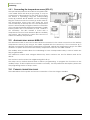
4.6 CONNECTING THE COMMUNICATION CABLES
The VarioString is fitted with 2 connectors RJ45/8 (8) (see chap. 4.1) that enable to transfer information
via a communication bus to other VarioStrings or to other equipment such as the RCC, the BSP or the
Xcom having the proprietary protocol of Studer Innotec. In this case, the installation should be
stopped and de-energized (the protection devices of power sources and loads should be open) to
complete the cable connection and positioning of the termination switches of all the devices
connected to the communication bus.
The max accumulated length of the communication bus is 300m. Due to a line voltage drop, it is
recommended to install only one RCC module at the end of a 300m line or a max of 2 modules at
the end of a 150m line. All the other modules of the system must be placed within the same radius of
a few meters (technical room).
A maximum of 3 RCC-02/03 or Xcom-232i may be connected to the same communication
line with a VarioString.
If a VarioString is connected to another compatible device (Xtender, VarioTrack, BSP, RCC,
Xcom) with the same communication bus, it is highly recommended to make a software
update of all components in the system in order to guarantee all functionalities.
The termination switch of the communication bus "Com. Bus" (9) remains in position T
(terminated) except when both connectors are used. In this case and only in this case, the
switch must be placed in the O (open) position. If one of the two connectors is not used,
the termination switch (9) will be in position T.

Studer Innotec SA
VarioString
18 V 1.2.1 User manual
The RCC-02/03 or Xcom-232i should not be placed between two devices connected to
the battery (Xtender, VarioTrack, or VarioString).
5 POWER-UP OF THE EQUIPMENT
The connection of the VarioString must be carried out in the following order. Any disassembly shall
be carried out in the reverse order. Before closing the protections and energizing the equipment,
check the polarity.
A. Connecting the battery: on the BAT+ and BAT- terminals
Check that the VarioString switches on (green LED “NIGHT” lights up on the
B. Connecting the photovoltaic panels: on the PV+ and PV- terminals
Check the PV voltage seen on the RCC. (if present)
Check the operation of the charger and the effective charging of the batteries when it is
sunny.
Your installation is now in operation. If the system requires specific configurations or settings, carry
them out immediately. Settings must be programmed by means of the remote control RCC-02/03 as
per chap. 8.2 or by means of the internal DIP switches as per chap. 8.1.
Saving of data in the datalog is activated only after the VarioString has completed the automatic
detection of the cabling type of the PV generators. In the case that the cabling configuration is
entered manually, the datalog is activated immediately.
It is imperative that the closing cover for the connection compartment is installed and
screwed tight before energizing the installation. There are dangerous voltages inside the
cable compartment.
If special configurations or settings are required for the system and they are set via internal
buttons or switches (DIP switch, see chap. 8.1), they should be set before connecting the
PV modules.
Une étincelle apparait au moment de brancher le deuxième pôle de la batterie. Ceci est
normal.
If the VarioString has been accidentally connected in reverse (battery reverse polarity on
the panel input), it is likely that the protection device on the battery cables is open. In such
case, recheck carefully the battery polarity, the wiring and the internal fuse of the
VarioString that protects against this situation. If after having closed or replaced the
protection device (f), the VarioString still does not work despite the correct polarity and
voltage of the battery, it must be brought back to the Seller for repair.

Studer Innotec SA
VarioString
User manual V 1.2.1 19
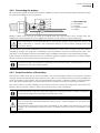
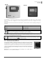
6 DISPLAY SYSTEM
The VarioString is fitted with a “Set” button and light indicators on the
front of the equipment allowing a clear identification of the operating
mode.
6.1 THE “SET” BUTTON (4)
The “Set” button can be used to start manually an equalization cycle
if this phase is authorized by the initial settings of the equipment. The
equalization phase will be authorized as from the beep after having
pressed the “Set” button (4) for 2 seconds. The “Charge” light indicator
flashes 3x as long as the equalization phase is not completed. The
equalization can be interrupted by pressing a second time for 2
seconds: a double beep indicates that the function has been
cancelled. The indicator (2) stops flashing 3x confirming the
cancellation.
Pressing the “Set” button (4) for 5 seconds until the second beep turns
off the VarioString. It starts again by pressing the “Set” button for 5
seconds.
6.2 “NIGHT” STANDBY INDICATOR (1)
This green indicator lights up when the VarioString is connected to a battery and ready to operate
but there is no PV voltage (at night or when no PV module is connected) or it is too low (inferior to
the battery voltage). This indicator flashes when there is a PV voltage but it is insufficient to charge
the batteries (at the beginning or at the end of the day). In order to save the battery power, the
VarioString charger turns off and goes in standby mode when this indicator lights up or flashes. It will
then consume less than 1W. The charger automatically switches on again when the sun starts shining
and PV voltage goes back above the battery voltage.
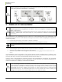
6.3 “CHARGE” CYCLE INDICATOR (2)
This yellow indicator lights up when the sun is shining and the photovoltaic generator produces
enough voltage for charging the batteries. Various flashing modes enable to distinguish in what
phase the regulator is. This indicator lights up continuously during the bulk phase. It flashes 1x during
the floating phase, 2x during the absorption phase and 3x during the equalization phase.
In “synchronized” mode, the cycle state – bulk, floating, absorption, equalization - are indicated.
When the VarioStrings(s) are connected to an Xtender system and the synchronization
{10037} is activated, the manual equalization can be started only during the battery cycle
of the Xtender which will then pilot the VarioString to carry out an equalization phase. In
“synchronized” mode, the cycle state - floating, absorption, equalization - are indicated. The
“charge” LED (2) and the indicator for the amount of charge are used when the equipment
is operating.

Studer Innotec SA
VarioString
20 V 1.2.1 User manual
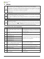
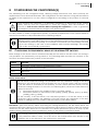
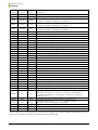
6.4 “ERROR” INDICATOR (3)
The table below describes the type of error according to the number of times this indicator blinks red.
Indic.
Indicated error
Comment
Off
No problem
If no indicator lights up, the equipment is de-energized.
On
The equipment is OFF
The equipment is energized but it does not operate because of
a user command (the “Set” button has been pressed for 5s).
Blinks
1x
Battery low voltage
warning
The equipment is still operating but shows that the battery is
lower than 40V.
Blinks
2x
Earth fault
The VarioString detects an abnormal situation which does not
correspond to the programmed value of the parameter
{14040}, {14041} and {14042} checking the state of the earth
connection. The VarioString turns off. It automatically starts
again when the normal situation is restored.
Blinks
3x
Power reduction or stop
due to an excessive
temperature in the
equipment.
This may be due to an excessive ambient temperature,
exposure of the equipment to a heat source (sun) or to
deficient or impeded ventilation.
Blinks
4x
Battery voltage higher
than 68V
Check the cause of this excessive voltage. The equipment
automatically starts again when voltage returns to a value
lower than 64V.
Blinks
5x
The PV voltage is higher
than the set value of the
max operating limit.
The PV voltage exceeds the max limit (600V in parallel or
independent, 900V in series). The equipment will stop or won’t
start. See also chap. 4.3.2.
Blinks
6x
Software incompatibility
in a system
The different parts of the system’s equipment must have the
same software version to function properly. Proceed with the
update following the procedure in the RCC-02/03 manual.
Blinks
7x
Not used
Blinks
8x
The PV current is higher
than the set value of the
max operating limit.
The PV current exceeds the max limit (13A in independent or in
series, 26A in parallel). The equipment will stop or won’t start.
See also chap. 4.3.3
Blinks
9x
Error in cabling of PV
modules
The cabling specified by the parameter {14002} does not
correspond to the cabling detected by the device.
Blinks
10x
Other errors
Internal error in system
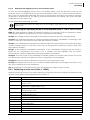
6.5 CHARGING CURRENT INDICATOR (5)-(6)-(7)-(8)-(9)-(10)
These indicators work as a type of histogram. They
blink or are lit up continually to indicate the range
of charge current from the VarioString given the
table to the right.
Example:
For a charge current of 65 A, the LEDS (5, 6, and 7)
are lit up continuously while the LED (8) is blinking.
The RCC-02/03 remote control allows a complete
and detailed display of the VarioString's behaviour
(see chap. 9.1).
Indicator nr
State
Signification
LED (10)
Lit
120A
Blinking
100-120A
LED (9)
Lit
>100A
Blinking
80-100A
LED (8)
Lit
>80A
Blinking
60-80A
LED (7)
Lit
>60A
Blinking
40-60A
LED (6)
Lit
>40A
Blinking
20-40A
LED (5)
Lit
>20A
Blinking
0-20A
Page is loading ...
Page is loading ...
Page is loading ...
Page is loading ...
Page is loading ...
Page is loading ...
Page is loading ...
Page is loading ...
Page is loading ...
Page is loading ...
Page is loading ...
Page is loading ...
Page is loading ...
Page is loading ...
Page is loading ...
Page is loading ...
Page is loading ...
Page is loading ...
Page is loading ...
Page is loading ...
Page is loading ...
Page is loading ...
Page is loading ...
Page is loading ...
Page is loading ...
Page is loading ...
Page is loading ...
Page is loading ...
Page is loading ...
Page is loading ...
Page is loading ...
Page is loading ...
Page is loading ...
Page is loading ...
Page is loading ...
Page is loading ...
-
 1
1
-
 2
2
-
 3
3
-
 4
4
-
 5
5
-
 6
6
-
 7
7
-
 8
8
-
 9
9
-
 10
10
-
 11
11
-
 12
12
-
 13
13
-
 14
14
-
 15
15
-
 16
16
-
 17
17
-
 18
18
-
 19
19
-
 20
20
-
 21
21
-
 22
22
-
 23
23
-
 24
24
-
 25
25
-
 26
26
-
 27
27
-
 28
28
-
 29
29
-
 30
30
-
 31
31
-
 32
32
-
 33
33
-
 34
34
-
 35
35
-
 36
36
-
 37
37
-
 38
38
-
 39
39
-
 40
40
-
 41
41
-
 42
42
-
 43
43
-
 44
44
-
 45
45
-
 46
46
-
 47
47
-
 48
48
-
 49
49
-
 50
50
-
 51
51
-
 52
52
-
 53
53
-
 54
54
-
 55
55
-
 56
56


Ask a question and I''ll find the answer in the document
Finding information in a document is now easier with AI
Related papers
-
STUDER RCC-02/-03 User manual
-
STUDER RCC-02 User manual
-
-
-
-
-
-
-
-
Other documents
-
STECA Solsum User manual
-
 Studer Innotec XTH 8000-48 User manual
-
-
WECO Studer Single Phase User guide
-
 Sigineer Power Solar Mate Installation & Operation Manual
-
 Studer Innotec XPC 2200-24 User manual
-
LOOM SOLAR FUSION-4024 User manual
-
 Compact C 4000-48 Operating instructions
-
 Studer Innotec HPC 2800-12 User manual
-
Voltronic Power Axpert Plus Duo User manual


