Page is loading ...

1
Max Drive System User
Manual

2
Suzhou Bafang Electric Motor Science-Technology
Co., Ltd.
www.szbaf.com

3
CONTENTS
IMPORTANT NOTICE ................................................................................................................................... 6
FOR YOUR SAFETY ....................................................................................................................................... 7
1. DRIVE UNIT
9
1.1 ADVANTAGES .......................................................................................................................................... 9
1.2 SCOPE OF APPLICATION ......................................................................................................................... 9
1.3 NAMING RULE ........................................................................................................................................ 9
1.4 MAIN TECHNICAL PARAMETERS ......................................................................................................... 11
1.5 DRIVE UNIT STRUCTURE AND DIMENSIONS....................................................................................... 12
2. SYSTEM INSTALLATION .................................................................................................................... 14
2.1 LIST OF TOOLS TO BE USED .................................................................................................................. 14
2.2 COMPONENT NAMES ........................................................................................................................... 15
2.3 DISPLAY INSTALLATION (DP C01.RS232.7 )................................................................................... 15
2.4 AUXILIARY KEYPAD INSTALLATION ..................................................................................................... 17
2.5 EXTERNAL RPM-DETECTING SENSOR INSTALLATION ....................................................................... 19
2.6 DRIVE UNIT INSTALLATION ................................................................................................................. 22
3. SYSTEM CABLING ................................................................................................................................ 30
3.1 LINK THE BATTERY CABLE TO THE DRIVE UNIT .................................................................................. 30
3.2 LINK THE EXTERNAL RPM-DETECTING SENSOR TO THE DRIVE UNIT .............................................. 31
3.3 LINK THE EB-BUS TO THE DRIVE UNIT .............................................................................................. 32
3.4 LINK THE HEADLIGHT CABLE TO THE DRIVE UNIT ............................................................................. 33

4
3.5 LINK THE TAILLIGHT TO THE DRIVE UNIT ........................................................................................... 33
3.6 LINK THE GEAR SENSOR TO THE DRIVE UNIT..................................................................................... 34
4. INSTALLATION OF THE FRONT CHAINWHEEL AND THE CHAIN COVER ....................... 35
4.1 INSTALLATION OF THE CHAINWHEEL (WITHOUT A CHAIN COVER) ................................................... 35
4.2 CHAIN COVER INSTALLATION (OPTIONAL) ........................................................................................ 37
4.3 CRANK INSTALLATION ......................................................................................................................... 44
5. DISPLAY .................................................................................................................................................. 46
5.1 SPECIFICATIONS AND PARAMETERS OF THE DISPLAY ........................................................................ 46
5.2 APPEARANCE AND DIMENSIONS ......................................................................................................... 46
5.3 FUNCTION OVERVIEW AND KEY DEFINITIONS ................................................................................... 47
FUNCTION OVERVIEW ....................................................................................................................................... 47
ITEMS TO BE SHOWN ON THE DISPLAY ........................................................................................................... 48
KEY DEFINITIONS ............................................................................................................................................... 49
5.4 NORMAL OPERATION .......................................................................................................................... 49
PAS LEVEL SELECTION ...................................................................................................................................... 49
DISTANCE MODE AND SPEED MODE SWITCH ................................................................................................ 50
HEADLIGHT/ BACKLIGHT SWITCH .................................................................................................................... 51
WALK ASSISTANCE MODE ................................................................................................................................ 51
BATTERY LEVEL INDICATION ............................................................................................................................. 52
5.5 PARAMETER SETTING ........................................................................................................................... 53
ITEMS TO BE SET: ............................................................................................................................................... 53
SETTING PREPARATION ..................................................................................................................................... 53
DATA RESET: ...................................................................................................................................................... 54
KM/ MILE: .......................................................................................................................................................... 55
LIGHT SENSITIVITY:............................................................................................................................................ 55
BACKLIGHT BRIGHTNESS: ................................................................................................................................. 55
AUTOMATIC OFF TIME: ..................................................................................................................................... 56

5
MAINTENANCE WARNING (INACTIVE BY DEFAULT): ...................................................................................... 56
ITEMS FOR SECONDARY SETTING: .................................................................................................................... 57
PASSWORD INPUT: ............................................................................................................................................ 57
SPEED LIMIT CHANGE: ...................................................................................................................................... 58
BATTERY COMMUNICATION: ............................................................................................................................ 59
5.6 ERROR CODE DEFINITIONS .................................................................................................................. 60
FAULT ALERT INTERFACE7. LIST OF MATERIALS ............................................................................. 62
8. AFTER-SALES AND WARRANTY POLICY ..................................................................................... 66

6
Important Notice
The Dealer Manual is to be used by professional e-bike mechanics. Users
who have not received training on electric bicycle assembly shall not
attempt to assemble parts and components even with the Dealer Manual.
If you doubt about any part of the manual, do not install the product.
Please consult the local sales office or an electric bicycle dealer for help.
Make sure to read all of the installation manuals delivered with the
product.
Do not disassemble or modify the product unless specified by the Dealer
Manual.
The Dealer Manual is available on our website (www.szbaf.com).
The dealer shall observe laws and regulations of the region, the state and
the country where the product is sold.
Make sure you have read this user manual carefully in order to use the
product properly.

7
For your Safety
Warning
When installing this product, be sure to follow the
instructions given in the user's manual.
It is recommended that you use only genuine Bafang parts at these times. The
bicycle may suddenly fall over and serious injury may result if bolts and nuts
are left loosened, or the product is damaged or improperly adjusted.
When performing maintenance operations (for example parts replacement),
be sure to wear goggles or eye patches to protect your eyes.
Please refer to the manual provided together with the product for
information uncovered by this manual.
After reading the user's manual carefully, keep it in a safe place for later
reference.
You must be aware that:
Do not give too much of your attention to the cycle display while riding,
otherwise you may fall off the bike.
Check that the wheels are securely installed to the bicycle before
commencing riding. If the wheels are not securely installed, the bicycle may
fall over and serious injury may result.
When riding a pedal-assisted electric bicycle, make sure that you are fully
familiar with the starting-off characteristics of the bicycle before riding it. If
the bicycle starts off suddenly, accidents may result.
Make sure the bicycle lights illuminate before riding at night.
Instructions on bicycle installation and maintenance
When cabling the product or installing the parts onto the bicycle, be sure to
disconnect the battery. Not doing so may result in electric shock.
When installing this product, be sure to follow the instructions given in the
user's manual. If bolts and nuts are left loosened or the product is damaged,
the bicycle may suddenly fall over and serious injury may result.

8
The frequency of maintenance will vary depending on the riding conditions.
Periodically clean the chain using an appropriate chain cleaner. Do not use
alkaline or acidic cleaning agents to remove rust under any circumstances. If
such cleaning agents are used, they may damage the chain and serious
injury may result.
Note
You must be aware of the following precautions:
Please follow instructions given in the user manual for your riding safety.
Examine the battery charger regularly for damage, especially the cable, plug
and enclosure. If the battery charger is damaged, it must not be used until it
has been repaired.
Please follow the guidance given by the safety supervisor or the instructions
indicated in the manual when using the product. This product is not
intended for use by persons (including children) with reduced physical,
sensory or mental capabilities, or lacking experience and knowledge, unless
they have been given supervision or instruction concerning use of the
product by a person responsible for their safety.
Do not allow children to play near the product.
Please consult the nearest dealer for any errors or problems.
Do not modify the system. Doing so may lead to malfunction of the system.
For information on product installation and adjustment, please consult your
dealer.
The product is designed to be fully waterproof to withstand wet weather
riding conditions. However, do not deliberately immerse it into water.
Do not clean the bicycle in a high-pressure wash. If water gets into any of
the components, operation problems or rusting may result.
When shipping the product with a high-speed vehicle in a rainy day,
remove the battery and put it in a safe place to stop it from getting wet due
to the rain.
Handle the product carefully, and avoid subjecting it to any strong shocks.
Some important information given in the user manual may also be found in
product labels.
When buying a spare key for the battery, be sure to provide the number on
the battery key. Please keep the number in your mind or your notebook.
Use a wrung-out damp cloth to clean the battery enclosure.

9
For any questions regarding the maintenance and use of the product,
please contact the dealer where you bought the product.
Natural wear and tear due to normal use and aging is not within our scope
of quality guarantee.
Please contact the seller for software updates (if any). The newest
information on software will be available on the home page of Bafang
website: www.szbaf.com
1. Drive Unit
1.1 Advantages
The controller ensures system safety with the fed-back torque signals and
dual speed signals (PAS speed signals and bicycle wheel RPM signals);
With a high starting torque and a maximum torque of no smaller than
80N.m, it is especially suitable for climbing;
High efficiency, low power consumption, and longer riding distance.
Low noise and smooth operation.
1.2 Scope of Application
The drive unit can work properly in the following environmental conditions:
Ambient temperature: (- 20- + 55) ℃;
Relative humidity: (15-95) % RH;
Note: The product can’t work normally if there is any major corrosive gas, any
medium that affects the product’s electrical insulation properties or any high-
intensity magnetic field.
1.3 Naming Rule

10
Naming Rule:
The nameplate is engraved on the shell, showing such information as follows:
MM G33.350
(1) 36V 250W
(2)
1511070036
(4) (3)
(1) MM G33.250─ Name of the drive unit;
(2) 36V─ Rated motor voltage;
(3) 250W─ Rated motor power;
(4) 151107─ Date of production, November 7, 2015 in this example;
0036─ Production serial number, ranging from 0000 to 9999; 0036 is the
production serial number of the 36th motor of the month.
MM G33.350.CB
(1) 36V 250W
(2)
1511070037
(4) (3)
(1) MM G33.250.CB─ Name of the drive unit, CB means it’s a coaster-brake
version;
(2) 36V─ Rated motor voltage;
(3) 250W─ Rated motor power;
(4)151107─ Date of production, November 7, 2015 in this example;
0037─ Production serial number, ranging from 0000 to 9999; 0036 is the
production serial number of the 36th motor of the month.

11
1.4 Main Technical Parameters
Classification
Freewheel version
Coaster brake
version
Rated voltage (DCV)
36
Rated power(W)
250
Rated efficiency (%)
≥80%
Max current
18A for the coaster brake version and 14A for
the freewheel version
Rated rotating speed(rpm)
100±5
Maximum torque(N.m)
≥80
Chain wheel
36T, 38T
Optional chain cover
full chain cover / P-shaped chain cover
Weight (Kg)
3.9
Sensors
PAS speed sensor, PAS torque sensor and
bicycle wheel RPM sensor and temperature
sensor
Noise (dB)
<55
Working environment
-20℃~55℃
Dust-proof/ water-proof
grade
IP66
Certification
CE ROHS/ EN14766/ EN14764/ REACH
Other functions
gear sensor module, DC 500mA/ 6V headlight
and taillight module, reprogramming function

12
1.5 Drive Unit Structure and Dimensions

13

14
2. System Installation
2.1 List of Tools to be Used
Compone
nts
Use of the Tools
Tools
Display
To fix the screw M4
Internal hexagonal
wrench
Drive Unit
To fix and remove the
chain wheel locknut
Socket spanner
To fasten M4 screws
which are used to fix the
chain cover binder plate
onto the drive unit.
Cross screwdriver
To fasten M6 bolts and
nuts which are used to
fix the drive unit onto
the frame adapter.
Internal hexagonal
wrench
To fasten the crank
mounting screw M8.
Internal hexagonal
wrench
RPM-
detecting
Sensor
To install the magnetic
steel.
Straight screwdriver
To fix the M5 screw for
the RPM-detecting
sensor.
Cross screwdriver
Battery
To fix M5 screws used to
fasten the battery pack
onto the carrier.
Internal hexagonal
wrench

15
2.2 Component Names
A. Drive unit
B. Front
chain
wheel
C. External
RPM-
detecting
sensor
D. Battery
E. Auxiliary
keypad
F. Display
2.3 Display Installation (DP C01.RS232.7 )
(E)
(D)
(B)
(A)
(F)
(C)

16
One or two rubber clamping rings may be needed depending on the
diameter of the handlebar (the applicable handlebar specifications
are Φ22.2, Φ25.4 and Φ31.8). Open the left or right display clamp, and
insert one or two clamping rings into the right position of the display
clamp as shown in the picture above.
A. a rubber clamping
ring (whose inner
diameter is Φ22.2 or
Φ25.4)
Left and right display
clamps for theΦ22.2
handlebar:
Left clamp -
2316020400017
Right clamp -
2316020400018
Left and right display
clamps for theΦ25.4
handlebar:
Left clamp -
2316020400007
Right clamp -
2316020400008
Insert the clamping ring(s) to each of the two display clamps
and mount them onto the handlebar. Use an internal
B. display clamp
C. hexagon socket head
cap screws M4*8

17
hexagonal wrench to fasten the left and right clamps onto the
handlebar.
Adjust the angle of the display so that the user can easily see
the display screen when riding. When the angle has been
adjusted, tighten the screws to the specified torque.
Tightening torque: 1N.m
Tool:
2.4 Auxiliary Keypad Installation

18
Open the auxiliary keypad and assemble it onto a position
that is easy for operation. Adjust the angle of the auxiliary
keypad to ensure that the keypad is easy to see during riding.
(Applicable to the handlebar whose external diameter is
Φ22.2mm)
A. keypad clamp
Fix the keypad onto the handlebar with a screw. Then tighten
the fixing screw with an internal hexagonal wrench.
Tightening torque: 1N.m
B. hexagon socket head
cap screw M3*8
Tool:

19
Match the female connector at the display with the male
connector at the EB-BUS as shown in the picture above.
H. female connector at
the display
h. male connector at the
EB-BUS
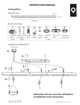
2.5 External RPM-detecting Sensor Installation
Before installing the external RPM-detecting sensor, please
make sure the gap between the speed-detecting sensor and
the magnetic steel is between 5 to 25 mm.
A. external RPM-
detecting sensor
B. magnetic steel
C. spokes
D. chain stay

20
If the gap is within the specified range, use the mounting
bolt to fix the speed sensor.
If the gap is over 25mm, please put spacers between the
sensor and the chain stay boss to reduce this gap.
Tightening torque: 1.5 - 2 N·m
A. dust cap
(2301030000003 )
B. mounting bolt M5*12
C. external RPM-
detecting sensor
D. sensor bracket (chain
stay boss)
Tool:
Mount the magnetic steel onto a spoke with the spoke stuck
in the magnetic steel.
A. external RPM-
detecting sensor
B. magnetic steel
(PS01010702/2308040000
001)
C. spokes
/