Lennox FXM 85 Installation, Operating And Maintenance Manual
- Category
- Heat pumps
- Type
- Installation, Operating And Maintenance Manual

lennoxemeia.com
FLEXY
FCM/FHM/FGM/FDM
FWH/FWM
Installation,
operating
and maintenance
Air cooled and water cooled
rooftop packaged units
85 > 234 kW
FLEXYII WSHP-IOM-1307-E


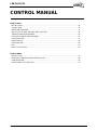
TABLE OF CONTENTS
FLEXYII_WSHP-IOM-1307-E - 1 -
INSTALLATION
OPERATION
MAINTENANCE MANUAL
Ref. FLEXYII_WSHP-IOM-1307-E
IMPORTANT NOTICE - Safety Instructions ....................................................................................................... 2
TRANSPORT - HANDLING - WARNING .............................................................................................................. 5
Delivery checks .............................................................................................................................................. 5
Rating plate .................................................................................................................................................... 5
Storage ........................................................................................................................................................... 5
Maintenance key ............................................................................................................................................ 5
Condensate drain ........................................................................................................................................... 5
Mandatory handling devices ........................................................................................................................... 6
Dimensions and weights ................................................................................................................................. 7
Lifting the units ............................................................................................................................................... 9
INSTALLATION .................................................................................................................................................... 10
Forklift protections .......................................................................................................................................... 10
Minimum clearance around the unit ................................................................................................................ 11
Duct connections ............................................................................................................................................ 12
WATER CONDENSING (water source heat pump only) ....................................................................................... 13
Water connection............................................................................................................................................ 13
Antifreeze ....................................................................................................................................................... 14
Water loop configuration ................................................................................................................................. 16
Pressure loss .................................................................................................................................................. 17
INSTALLATION OF A ROOF MOUNTING FRAME ............................................................................................. 18
Curbing and flashing ...................................................................................................................................... 19
Non-adjustable non-assembled roof curb installation ..................................................................................... 20
Energy recovery installation ........................................................................................................................... 22
SERVICE MANUAL .............................................................................................................................................. 31

IMPORTANT NOTICE – Safety instructions
FLEXYII_WSHP-IOM-1307-E - 2 -
The present manual applies to the following ROOFTOP versions:
FCM 85 - FCM 100 - FCM 120 - FCM 150 - FCM 170 - FCM 200 - FCM 230
FHM 85 - FHM 100 - FHM 120 - FHM 150 - FHM 170 - FHM 200 - FHM 230
FDM 85 - FDM 100 - FDM 120 - FDM 150 - FDM 170 - FDM 200 - FDM 230
FGM 85 - FGM 100 - FGM 120 - FGM 150 - FGM 170 - FGM 200 - FGM 230
FWH 85 - FWH 100 - FWH 120 – FWH150 – FWH170
FWM 85 - FWM 100 - FWM 120 – FWM150 – FWM170
FXM 25 - FXM 30 - FXM 35 - FXM 40 - FXK 55 – FXM 70 - FXM 85 - FXM 100 - FXM 110 - FXM 150 - FXM 170
NOTES FOR UNIT FITTED WITH GAS BURNER:
THE UNIT MUST BE INSTALLED IN ACCORDANCE WITH LOCAL SAFETY CODES
AND REGULATIONS AND CAN ONLY BE USED IN WELL VENTILATED AREA.
IF MACHINE IS INCLUDING GAZ BURNER, MINIMUM CLEARANCE AROUND THE
UNIT MUST BE AT LEAST 8 M TO ALLOW A PROPER GAZ FLUE DILUTION. IF NOT
POSSIBLE, THE FRESH AIR INTAKE MUST BE DUCTED AT LEAST 8 M AWAY
FROM THE GAS BURNER EXHAUST.
PLEASE READ CAREFULLY THE MANUFACTURER’S INSTRUCTIONS BEFORE
STARTING THIS UNIT.
Switchgear must be installed on each unit in accordance with the Machine
Directive and the standard NF EN 60204.
THIS MANUAL IS ONLY VALID FOR UNITS DISPLAYING THE FOLLOWING
CODES: GB IR GR DA NO FI IS
In case these symbols are not displayed on the unit, please refer to the technical
documentation which will eventually detail any modifications required to the
installation of the unit in a particular country.
All the technical and technological information contained in this manual, including any drawing and technical descriptions
provided by us, remain the property of Lennox and must not be used (except in operation of this product), reproduced, issued
to or made available to third parts without the prior written agreement of Lennox.
The technical informations and specifications contained in this manual are for reference only. The manufacturer reserves the right to modify
these without warning and without obligation to modify equipment already sold.

IMPORTANT NOTICE – Safety instructions
FLEXYII_WSHP-IOM-1307-E - 3 -
All FLEXY II Units are compliant with the PED directive 97-23/CE
The following note must be followed carefully
All work on the unit must be carried out by a qualified and authorised employee.
Non-compliance with the following instructions may result in injury or serious accidents.
Work on the unit:
• The unit shall be isolated from the electrical supply by disconnection and locking using the main isolating switch.
• Workers shall wear the appropriate personal protective equipment (helmet, gloves, glasses, etc.).
Work on the electrical system:
• Work on electric components shall be performed with the power off by employees having valid electrical qualification and
authorisation.
Work on the refrigerating circuit(s):
• Monitoring of the pressures, draining and filling of the system under pressure shall be carried out using connections provided
for this purpose and suitable equipment.
• To prevent the risk of explosion due to spraying of coolant and oil, the relevant circuit shall be drained and at zero
pressure before any disassembly or unbrazing of the refrigerating parts takes place.
• There is a residual risk of pressure build-up by degassing the oil or by heating the exchangers after the circuit has been
drained. Zero pressure shall be maintained by venting the drain connection to the atmosphere on the low pressure side.
• The brazing shall be carried out by a qualified brazier. The brazing shall comply with standard NF EN1044 (minimum 30%
silver).
Replacing components:
• In order to maintain CE marking compliance, replacement of components shall be carried out using spare parts, or using
parts approved by Lennox.
• Only the coolant shown on the manufacturer’s nameplate shall be used, to the exclusion of all other products (mix of
coolants, hydrocarbons, etc.).
CAUTION:
In the event of fire, refrigerating circuits can cause an explosion and spray coolant gas and oil.
TRANSPORT – HANDLING:
- Never lift the unit without forklift protections
- Remove the forklift protection before installation
- An approach ramp must be installed if the unit’s installation requirements tell that it's necessary to reach the main switch.
This recommendation is valid for installations in general and in particular for return and curbs. It’s also valid to reach other parts
of the unit: filters, refrigerant circuit, etc…
- It’s advised to fix curbs and roofcurbs to the unit
- Whatever the supply configuration is, respect a minimal duct’s length of 2m before any elbow or any duct’s section change.
COMMISSIONING:
- It must only be carried out by trained refrigeration engineers.
- Don’t forget to open the insulation valve on the liquid line before starting the unit
FILTERS:
- Do the filters fire classification’s choice according to local regulations.
FANSTART:
- Any adjustment has to be done power stopped.
GAS:
- Any work on gas module must be carried out by qualified personnel
- A unit with gas module must be installed in accordance with local safety codes and regulations and can only be used in
planed installation conditions for outdoor.
- Before commissioning this type of unit, it’s mandatory to ensure that the gas distribution system is compatible with the
adjustment and settings of the unit.

IMPORTANT NOTICE – Safety instructions
FLEXYII_WSHP-IOM-1307-E - 4 -
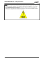
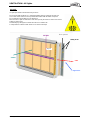
UV LIGHT :
- The UV lamp emits shortwave UV-C ultraviolet radiation which is harmful to skin and eyes
- It can cause serious skin burns and eye inflammation within ONE SECOND of exposure
- Do not enter the machine while UV are switched on
- Make sure the UV light circuit breaker is OFF when opening the return air section door and the supply air section doors
- The following logo will appear to inform about the UV-C radiation risk

TRANSPORT – HANDLING – WARNING
FLEXYII_WSHP-IOM-1307-E - 5 -
DELIVERY CHECKS
On receipt of a new equipment please check the following
points. It is the customer’s responsibility to ensure that the
products are in good working order:
- The exterior has not been damaged in any way.
- The lifting and handling equipment are suitable for the
equipment and comply with the specifications of the
handling instructions enclosed here-in.
- Accessories ordered for on site installation have been
delivered and are in good working order.
- The equipment supplied corresponds to the order and
matches the delivery note.
If the product is damaged, exact details must be confirmed
in writing by registered post to the shipping company within
48 hours of delivery (working days). A copy of the letter
must be addressed to Lennox and the supplier or
distributor for information purposes. Failure to comply will
invalidate any claim against the shipping company.
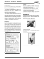
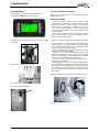
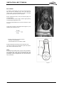
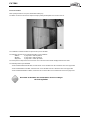
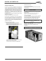
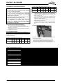
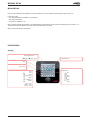
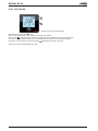
RATING PLATE
The rating plate provides a complete reference for the
model and ensures that the unit corresponds to the model
ordered. It states the electrical power consumption of the
unit on start-up, its rated power and its supply voltage. The
supply voltage must not deviate beyond +10/-15 %. The
start-up power is the maximum value likely to be achieved
for the specified operational voltage. The customer must
have a suitable electrical supply. It is therefore important to
check whether the supply voltage stated on the unit's rating
plate is compatible with that of the mains electrical supply.
The rating plate also states the year of manufacture as well
as the type of refrigerant used and the required charge for
each compressor circuit.
Fig. 1
STORAGE
When units are delivered on site they are not always
required immediately and are sometimes put into storage.
In the event of medium to long-term storage, we
recommend the following procedures:
- Ensure that there is no water in the hydraulic systems.
- Keep the heat exchanger covers in position (AQUILUX cover).
- Keep protective plastic film in position.
- Ensure the electrical panels are closed.
- Keep all items and options supplied in a dry and clean
place for future assembly before using the equipment.
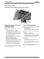
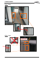
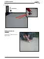
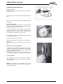
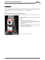
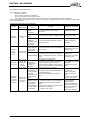
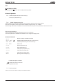
MAINTENANCE KEY
On delivery we recommend that you keep the key which is
attached to an eyebolt in a safe and accessible place. This
allows you to open the panels for maintenance and
installation work.
The locks are ¼ turn + then tighter (figure 2).
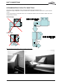
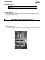
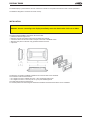
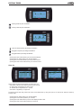
CONDENSATE DRAINS
The condensate drains are not assembled when delivered
and are stored
in the electrical panel with their clamping collars.
To assemble them, insert them on the condensate tray outlets
Fig. 3

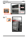
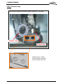
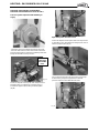
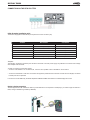
TRANSPORT – HANDLING
FLEXYII_WSHP-IOM-1307-E - 6 -
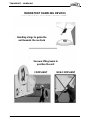
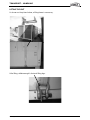
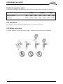
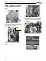
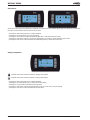
Handling slings to guide the
unit towards the roofcurb
Vacuum lifting beam to
position the unit
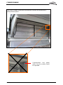
COMPLIANT
NON-COMPLIANT
MANDATORY HANDLING DEVICES

TRANSPORT – HANDLING
FLEXYII_WSHP-IOM-1307-E - 7 -
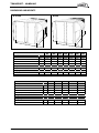
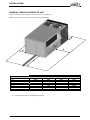
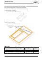
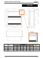
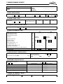
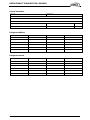
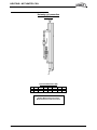
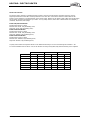
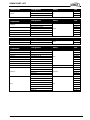
DIMENSIONS AND WEIGHTS
FLEXY2
FCM/FHM/FGM/FDM
85
100
120
150
170
200
230
View (F, G, H box)
F BOX
F BOX
F BOX
G BOX
G BOX
H BOX
H BOX
A
mm
2200
2200
2200
2200
2200
2200
2200
B
mm
3350
3350
3350
4380
4380
5533
5533
C
mm
1510
1510
1510
1834
1834
2134
2134
D
mm
360
360
360
450
450
615
615
Weight of standard units FCM
kg
990
1065
1141
1442
1505
1752
2052
Weight gas unit FGM
Standard heat
kg
1097
1172
1248
1683
1746
2016
2316
High heat
kg
1167
1242
1318
1706
1769
2056
2356
WSHP
FWH/FWM
85
100
120
150
170
View (F & G box)
F BOX
F BOX
F BOX
G BOX
G BOX
A
mm
2200
2200
2200
2200
2200
B
mm
3350
3350
3350
4380
4380
C
mm
1510
1510
1510
1834
1834
D
mm
360
360
360
450
450
Weight of standard units FWH
kg
867.7
874.7
1045.4
1225.8
1314.8
Weight gas unit FWM
Standard heat
kg
999.1
989
1174.4
1461.2
1571.6
High heat
kg
1060
1049.9
1235.3
1500.5
1610.9
F & G BOX
H BOX
A
D
B
C
D
A
B
C

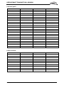
TRANSPORT – HANDLING
FLEXYII_WSHP-IOM-1307-E - 8 -
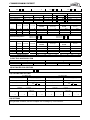
DIMENSIONS AND WEIGHTS
LENGTH
HEIGHT
WIDTH
HOOD
WEIGHT
mm mm mm
Side
Fan
Standard
mm
mm
kg
FXM025
4070
1635
1055
490
600
950
FXM030
4070
1635
1055
490
600
980
FXM035
4750
2255
1290
490
600
1400
FXM040
4750
2255
1290
490
600
1450
FXM055
4750
2255
1290
490
600
1600
FXM070
5050
2255
1725
890
600
1800
FXM085
5050
2255
1725
890
600
1900
FXM100
5050
2255
1725
890
600
2000
FXM110
5650
2255
2000
860
-
2620
FXM140
5650
2255
2000
860
-
2620
FXM170
5650
2255
2000
860
-
2650

TRANSPORT – HANDLING
FLEXYII_WSHP-IOM-1307-E - 9 -
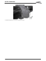
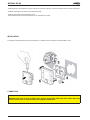
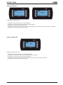
LIFTING THE UNIT
As shown on the picture below, a lifting frame is necessary.
After lifting, withdraw angle’s feet and lifting lugs.

INSTALLATION
FLEXYII_WSHP-IOM-1307-E - 10 -
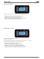
FORKLIFT PROTECTIONS
NEVER LIFT THE UNIT WITHOUT FORKLIFT PROTECTIONS
REMOVE THE FORKLIFT PROTECTIONS
BEFORE INSTALLATION
PRELIMINARY CHECKS
Before installing the equipment, the following points MUST
be checked:
- Have the forklift protections been removed?
- Is there sufficient space for the equipment?
- Is the surface on which the equipment is to be
installed sufficiently solid to withstand its weight? A
detailed study of the frame must be made beforehand.
- Do the supply and return ductwork openings
excessively weaken the structure?
- Are there any obstructing items which could hinder the
operation of the equipment?
- Does the electrical power available correspond to the
equipment's electrical specifications?
- Is drainage provided for the condensate?
- Is there sufficient access for maintenance?
- Installation of the equipment could require different
lifting methods which may vary with each installation
(helicopter or crane). Have these been evaluated?
- Ensure that the unit is installed in accordance with the
installation instructions and local applicable codes.
- Check to ensure that the refrigerant lines do not rub
against the cabinet or against other refrigerant lines.
In general, make sure no obstacles (walls, trees or roof
ledges) are obstructing the duct connections or hindering
assembly and maintenance access.
INSTALLATION REQUIREMENTS
The surface on which the equipment is to be installed must
be clean and free of any obstacles which could hinder the
flow of air to the condensers:
-Avoid uneven surfaces
-Avoid installing two units side by side or close to each
other as this may restrict the airflow to the condensers.
Before installing a packaged Rooftop unit it is important to
understand:
- The direction of prevailing winds
-The direction and position of air flows.
-The external dimensions of the unit and the
dimensions of the supply and return air connections.
-The arrangement of the doors and the space required
to open them to access the various components.
CONNECTIONS
-Ensure that all the pipe-work crossing walls or roofs
are secured, sealed and insulated.
-To avoid condensation problems, make sure that all
pipes are insulated according to the temperatures of
fluids and type of rooms.
NOTE: The AQUILUX protection sheets fitted to the finned
surfaces must be removed prior to start up.

INSTALLATION
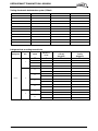
FLEXYII_WSHP-IOM-1307-E - 11 -
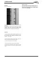
MINIMUM CLEARANCE AROUND THE UNIT
Figure 4 shows the required clearances and service access around the unit.
NOTE: Ensure the fresh air inlet does not face prevailing wind direction.
A
B
C
D
FCM/FHM/FGM/FDM/FWH/FWM
F BOX
2200 (1)
2000
2000
2000
G BOX
2700 (1)
2000
2000
2000
H BOX
2700 (1)
2000
2000
2000
FX
25 & 30
*
1100
*
1700
35à55
*
1300
*
2300
70à100
*
1700
*
2300
110à170
*
2000
*
2300
(1) Add 1 meter if the units are equipped with gas burner
A
B
C
D

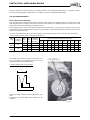
DUCT CONNECTIONS
FLEXYII_WSHP-IOM-1307-E - 12 -
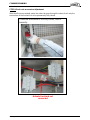
RECOMMENDATIONS FOR DUCTS CONNECTIONS
Some rules must be complied with for the connections between ducts and unit done on site.
Whatever the supply configuration is, respect a minimal duct’s length (D) of 2m before any elbow or any duct’s diameter
change.
These recommendations are imperative in the case of 2 independent turbines (sizes from 150kW to 230kW and all units
equipped with gas module)
Horizontal supply
Vertical supply
Here are obvious bad examples of ducts connections noted on site:
D ≥ 2m
D ≥ 2m
D ≤ 2m
D ≤ 2m

WATER CONDENSING
FLEXYII_WSHP-IOM-1307-E - 13 -
WATER SOURCE HEAT PUMP ONLY
Water connections
The water circulating pump will be preferably installed upstream so that the evaporator/condenser will be subjected to positive
pressure. Inlet and Outlet water connections are indicated on the certified drawing sent with the unit or shown in the sales
brochure.
The water pipes connected to the unit must not transmit any radial or axial force or any vibration to the heat exchangers.
It is important to follow non exhaustive recommendations hereunder:
• Comply with the water inlet and outlet connections shown on the unit.
• Install manual or automatic air purge valves at all high points in the circuit.
• Install a safety valve as well as an expansion tank to maintain the circuit pressure.
• Install thermometers in both the inlet and outlet water connections.
• Install drain connections at all low points to allow the whole circuit to be drained.
• Install stop valves, close to the inlet and outlet water connections.
• Use flexible connections to reduce vibrations transmission.
• After testing for leaks, insulate all pipe work, to reduce thermal leaks and to prevent condensation.
• If the external water pipes are in an area, where the ambient temperature is likely to fall below 0°C, insulate the piping and
add an electric heater.
• Ensure full earthling continuity
A drainage plug is located at the base of the evaporator. A drainage pipe may be connected to this to enable drainage of
evaporator water for service operations or for seasonal shut down.
Connections at the inlet and outlet are Victaulic type.
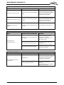
Water analysis
The water must be analysed; the water circuit installed must include all items necessary for water treatment: filters, additives,
intermediate exchangers, bleed valves, vents, isolating valves etc... depending on the results of the water analysis.
We do not advise operation of the units with open loops which can cause troubles with oxygenation, or
operation with untreated ground water.
Use of untreated or improperly treated water can cause deposits of scale, algae and sludge or cause corrosion and erosion. It is
advisable to call in a qualified water treatment specialist to determine what kind of treatment will be necessary. The
manufacturer cannot accept liability for damage caused by the use of untreated or improperly treated water, salt water or brine.
Here are our non exhaustive recommendations given as an indication:
• No NH4+ ammonium ions in the water, they are very detrimental for copper. <10mg/l
• Cl- Chloride ions are detrimental for copper with a risk of perforations by corrosion by puncture. < 10 mg/l.
• SO42- sulphate ions can cause perforating corrosion.< 30 mg/l.
• No fluoride ions (<0.1 mg/l).
• No Fe2+ and Fe3+ ions with dissolved oxygen. Dissolved iron < 5 mg/l with dissolved oxygen < 5 mg/l. Over
those values, it means a corrosion of steel which may generate a corrosion of copper parts under deposite of Fe – this is
mainly the case with shell and tube heat exchangers.
• Dissolved silicon: silicon is an acid element of water and can also lead to corrosion risks. Content < 1mg/l.
• Water hardness: TH >2.8 K. Values between 10 and 25 can be recommended. This will facilitate scale deposit that can limit
corrosion of copper. TH values that are too high can cause piping blockage over time.
• TAC< 100.
• Dissolved oxygen: Any sudden change in water oxygenation conditions must be avoided. It is as detrimental to
deoxygenate the water by mixing it with inert gas as it is to over-oxygenate it by mixing it with pure oxygen. The disturbance
of the oxygenation conditions encourages destabilisation of copper hydroxides and enlargement of particles.
• Specific resistance – electric conductivity: the higher the specific resistance, the slower the corrosion tendency. Values
above 3000 Ohm/cm are desirable. A neutral environment favours maximum specific resistance values.
For electric conductivity values in the order of 200-6000 S/cm can be recommended.
• pH: pH neutral at 20°C (7 < pH < 8)

WATER CONDENSING
FLEXYII_WSHP-IOM-1307-E - 14 -
Antifreeze protection
Use glycol/water solution
ADDITION OF GLYCOL IS THE ONLY EFFICIENT WAY TO PROTECT AGAINST FREEZING
The glycol/water solution must be sufficiently concentrated to ensure proper protection and prevent formation of
ice at the lowest outdoor air temperatures expected on an installation. Take precautions when using non
passivated MEG antifreeze solutions (Mono Ethylene Glycol or MPG Mono Propylene Glycol). Corrosion can
occur with these antifreeze solutions with oxygen.
Drain the installation
To enable drainage of the circuit, make sure that drain cocks are installed at all the low points of the circuit.
To drain the circuit, the drain cocks must be opened and an air inlet ensured.
Note : air bleeders are not designed to admit air.
EVAPORATOR FREEZING DUE TO COLD WEATHER CONDITIONS IS NOT COVERED BY LENNOX
WARRANTY.
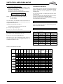
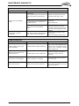
Minimum water content
The minimum volume of the rooftop water circuit must be determined. If necessary, install a buffer tank. Proper operation of
regulating and safety devices can only be ensured if the volume of water is sufficient.
The theoretical volume of the water loop for a proper air conditioning operation can be calculated using the formulas hereafter:
WATER COOLED FLEXYII RANGE
Vt à Minimum water content of the installation
Q à Water capacity in kW
N à Number of control steps available in the unit
Dt à Maximum acceptable temperature rise (Dt = 6°c for an air conditioning application)
Vmini = 86 x Q / (N x Dt)
Unit Size
Number of
stages
Mini Water
Volume (L)
FWH/FWM 085
FWH/FWM 100
FWH/FWM 120
FWH/FWM 150
FWH/FWM 170
2
2
2
3
4
631
781
867
702
627
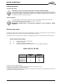
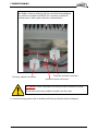
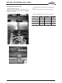
Victaulic connection assembly instruction
Be careful not to roll or pinch the seal when installing the half-shells. This would cause a leak.
1-Install the bolts and tighten the nuts by hand on them.
2- tighten bolts uniformly passing from one side to the other, until the pads for the bolts are in metal-metal contact. Make sure
the shoulders are well engaged in the grooves.

WATER CONDENSING
FLEXYII_WSHP-IOM-1307-E - 15 -
It is imperative to tighten the nuts evenly to avoid pinching the gasket.

WATER CONDENSING
FLEXYII_WSHP-IOM-1307-E - 16 -
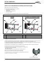
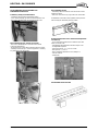
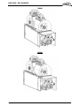
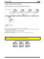
WATER LOOP CONFIGURATION (FOR WATER SOURCE HEAT PUMP)
Figures below show the 2 water configurations.
Figure 1 indicates all components used as standard :
• the electronic water flow switch,
• the water filter,
• the pressure taps and drain valves,
• the automatic airvent,
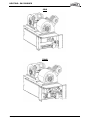
The second figure shows rooftop water loop with Low Water Loop Temperature option.
LOW WATER LOOP TEMPERATURE (OPTION)
In order to operate with low water inlet temperature in cooling mode (ie: ground source water loops) it is necessary to control
the water flow rate in the heat exchanger to maintain a minimum condensing pressure in the refrigeration circuit.
In cooling mode the CLIMATIC 60 will control the water flow rate in the condenser by monitoring the condensing pressure and
by closing the water flow valve accordingly by a 0-10 Volts signal.
This option offers a second opportunity: give the possibility to close the rooftop water loop when compressors are stopped.
Warning: the valve does not allow to do the balance on customer circuit
Several checks have been to do to avoid creating perturbations on customer circuit :
- check valve pressure drop at water flow
-use variable speed pump.
- adjust water flow switch set up at small water flow acceptable by the unit
WATER FILTER REPLACEMENT (ONLY FOR WATER SOURCE HEAT PUMP)
It is important that units are serviced regularly by a qualified technician, at least once
every year or every 1000 hours of operation.
1
All Victaulic Connections
5
Pressure Taps and drain Valve
2
Inlet Water Filter
6
Stainless steel Exchanger
3
Automatic Air Vent
7
ElectroValve (HP control option)
4
Electronic Flow Switch
2
1
3
4
5
6
1
2
3
4
5
6
7
Low Water Loop Temperature Option
Hydraulic Data
Standard
Access for cartridge cleaning
Figure 1
Figure 2

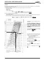
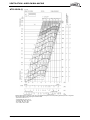
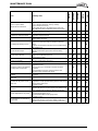
WATER CONDENSING
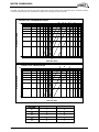
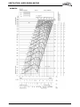
FLEXYII_WSHP-IOM-1307-E - 17 -
CAUTION: The water circuit may be pressurised. Observe the usual precautions when depressurising the circuit before opening
it. Failure to observe these rules could lead to accidents and cause injury to service personal.
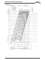
FWH/FWM
Exchanger Curve Filter Curve
85
C
B
100
D
B
120
D
B
150
E
C
170
E
C
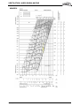
Pressure Loss - Heat plate Exchanger
A
B
C
D
E
10
100
110 100
Water flow (m3/h)
Pressure Loss (kPa)
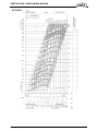
Pressure Loss - WATER FILTER
A
B
C
1.0
10.0
110 100
Water flow (m3/h)
Pressure Loss (kPa)

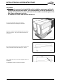
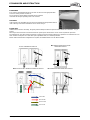
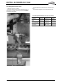
INSTALLATION ON A ROOFMOUNTING FRAME
FLEXYII_WSHP-IOM-1307-E - 18 -
CAUTION:
- An approach ramp must be installed if the unit’s installation requirements tell that it's
necessary to reach the main switch. This recommendation is valid for installations in
general and in particular for return and curbs. It’s also valid to reach other parts of the
unit: filters, refrigerant circuit, etc…
- It’s advised to fix curbs and roofcurbs to the unit.
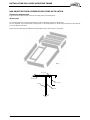
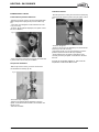
As levels are adjustable, observe the following
recommendations when installing the equipment
Above all, ensure that all the adjustable returns are facing
outward (“1” figure 4). They are usually turned inside-out
for transport.
Place the roof mounting frame on the trimmer beam by first
lining up the inlet and the outlet opening. (“2”- figure 5)
After levelling the frame, secure the adjustable returns on
the trimmer.
It is important to centre the unit on the roof frame
•
Fig. 4
Fig. 5
Fig. 6
Page is loading ...
Page is loading ...
Page is loading ...
Page is loading ...
Page is loading ...
Page is loading ...
Page is loading ...
Page is loading ...
Page is loading ...
Page is loading ...
Page is loading ...
Page is loading ...
Page is loading ...
Page is loading ...
Page is loading ...
Page is loading ...
Page is loading ...
Page is loading ...
Page is loading ...
Page is loading ...
Page is loading ...
Page is loading ...
Page is loading ...
Page is loading ...
Page is loading ...
Page is loading ...
Page is loading ...
Page is loading ...
Page is loading ...
Page is loading ...
Page is loading ...
Page is loading ...
Page is loading ...
Page is loading ...
Page is loading ...
Page is loading ...
Page is loading ...
Page is loading ...
Page is loading ...
Page is loading ...
Page is loading ...
Page is loading ...
Page is loading ...
Page is loading ...
Page is loading ...
Page is loading ...
Page is loading ...
Page is loading ...
Page is loading ...
Page is loading ...
Page is loading ...
Page is loading ...
Page is loading ...
Page is loading ...
Page is loading ...
Page is loading ...
Page is loading ...
Page is loading ...
Page is loading ...
Page is loading ...
Page is loading ...
Page is loading ...
Page is loading ...
Page is loading ...
Page is loading ...
Page is loading ...
Page is loading ...
Page is loading ...
Page is loading ...
Page is loading ...
Page is loading ...
Page is loading ...
Page is loading ...
Page is loading ...
Page is loading ...
Page is loading ...
Page is loading ...
Page is loading ...
Page is loading ...
Page is loading ...
Page is loading ...
Page is loading ...
Page is loading ...
Page is loading ...
Page is loading ...
Page is loading ...
-
 1
1
-
 2
2
-
 3
3
-
 4
4
-
 5
5
-
 6
6
-
 7
7
-
 8
8
-
 9
9
-
 10
10
-
 11
11
-
 12
12
-
 13
13
-
 14
14
-
 15
15
-
 16
16
-
 17
17
-
 18
18
-
 19
19
-
 20
20
-
 21
21
-
 22
22
-
 23
23
-
 24
24
-
 25
25
-
 26
26
-
 27
27
-
 28
28
-
 29
29
-
 30
30
-
 31
31
-
 32
32
-
 33
33
-
 34
34
-
 35
35
-
 36
36
-
 37
37
-
 38
38
-
 39
39
-
 40
40
-
 41
41
-
 42
42
-
 43
43
-
 44
44
-
 45
45
-
 46
46
-
 47
47
-
 48
48
-
 49
49
-
 50
50
-
 51
51
-
 52
52
-
 53
53
-
 54
54
-
 55
55
-
 56
56
-
 57
57
-
 58
58
-
 59
59
-
 60
60
-
 61
61
-
 62
62
-
 63
63
-
 64
64
-
 65
65
-
 66
66
-
 67
67
-
 68
68
-
 69
69
-
 70
70
-
 71
71
-
 72
72
-
 73
73
-
 74
74
-
 75
75
-
 76
76
-
 77
77
-
 78
78
-
 79
79
-
 80
80
-
 81
81
-
 82
82
-
 83
83
-
 84
84
-
 85
85
-
 86
86
-
 87
87
-
 88
88
-
 89
89
-
 90
90
-
 91
91
-
 92
92
-
 93
93
-
 94
94
-
 95
95
-
 96
96
-
 97
97
-
 98
98
-
 99
99
-
 100
100
-
 101
101
-
 102
102
-
 103
103
-
 104
104
-
 105
105
-
 106
106


Lennox FXM 85 Installation, Operating And Maintenance Manual
- Category
- Heat pumps
- Type
- Installation, Operating And Maintenance Manual
Ask a question and I''ll find the answer in the document
Finding information in a document is now easier with AI
Related papers
-
Lennox V8DRNP-04 (12A57) Water Pump Kit Installation guide
-
-
-
Lennox AIRCOOLAIR ASH Series Application Manual
-
Lennox Rooftop Unit Operating instructions
-
-
Lennox CORE Service App Operating instructions
-
Lennox BAM 085 DSM 3M Installation, Operating And Maintenance Manual
-
-
Other documents
-
Sulzer CP 112, CP 212 Installation guide
-
Greenheck 485923 Quick start guide
-
nilan Compact S CTS 602 User manual
-
-
 eControls T200WLD User& Installer's Manual
-
 Kaysun KFC-S-2T-500D User manual
-
Western Omega Sky Xi Installation and Operating Instructions
-
-
-

