Page is loading ...

®
CYDIO 96HE
PCI Express Digital I/O Board - 96
Channels, High Current, 100-Pin
High-Density Connector
Digital I/O
USER’S MANUAL
VER. 2.0C• Sep-09
No part of this manual may be reproduced without permission
CyberResearch
®
,Inc.
www.cyberresearch.com
25 Business Park Dr., Branford, CT 06405 USA
203-643-5000 (9
A.M. to 5 P.M. EST) FAX: 203-643-5001


CyberResearch
®
Digital I/O
CYDIO 9HE
©Copyright 2009
All Rights Reserved.
September 2, 2009
The information in this document is subject to change without prior notice in order
to improve reliability, design, and function and does not represent a commitment
on the part of CyberResearch, Inc.
In no event will CyberResearch, Inc. be liable for direct, indirect, special,
incidental, or consequential damages arising out of the use of or inability to use
the product or documentation, even if advised of the possibility of such damages.
This document contains proprietary information protected by copyright. All rights
are reserved. No part of this manual may be reproduced by any mechanical,
electronic, or other means in any form without prior written permission of
CyberResearch, Inc.
Trademarks
“CyberResearch,” and “CYDIO 9HE,” are trademarks of CyberResearch, Inc.
Other product names mentioned herein are used for identification purposes only
and may be trademarks and/or registered trademarks of their respective
companies.
• NOTICE •
CyberResearch, Inc. does not authorize any CyberResearch product for use in life
support systems, medical equipment, and/or medical devices without the written
approval of the President of CyberResearch, Inc. Life support devices and
systems are devices or systems which are intended for surgical implantation into
the body, or to support or sustain life and whose failure to perform can be
reasonably expected to result in injury. Other medical equipment includes devices
used for monitoring, data acquisition, modification, or notification purposes in
relation to life support, life sustaining, or vital statistic recording. CyberResearch
products are not designed with the components required, are not subject to the
testing required, and are not submitted to the certification required to ensure a
level of reliability appropriate for the treatment and diagnosis of humans.
CyberResearch, Inc. iii
25 Business Park Drive P: (203) 643-5000; F: (203) 643-5001
Branford, CT USA www.cyberresearch.com

CYDIO 9HE CyberResearch
®
Digital I/O
iv ©Copyright 2009 CyberResearch, Inc.
Revision History
Revision # Description Date of Issue
1.0 Initial Release September 2009
2.0C Revision September 2, 2009

Table of Contents
Preface
About this User's Guide .......................................................................................................................2
What you will learn from this user's guide .........................................................................................................2
Conventions in this user's guide .........................................................................................................................2
............................................................................................................................................................................2
Chapter 1
Introducing the CYDIO 96HE................................................................................................................3
Overview: CYDIO 96HE features......................................................................................................................3
CYDIO 96HE block diagram .............................................................................................................................4
Chapter 2
Installing the CYDIO 96HE....................................................................................................................5
What comes with your CYDIO 96HE shipment?...............................................................................................5
Hardware .......................................................................................................................................................................... 5
Optional components ........................................................................................................................................................ 5
Unpacking the CYDIO 96HE.............................................................................................................................6
Installing the software ........................................................................................................................................6
Installing the hardware .......................................................................................................................................6
Connecting the board for I/O operations ............................................................................................................7
Main I/O connector........................................................................................................................................................... 7
Connector pin out.............................................................................................................................................................. 8
Cabling.............................................................................................................................................................................. 9
Chapter 3
Functional Details...............................................................................................................................10
CYERB 24 and CYSSR 24 daisy chain configuration .....................................................................................10
82C55 emulation (mode 0) ...............................................................................................................................10
Replacing a fuse ...............................................................................................................................................11
Fuse specifications...........................................................................................................................................................11
Chapter 4
Specifications......................................................................................................................................12
Digital input / output.........................................................................................................................................12
Power Consumption .........................................................................................................................................12
Environmental ..................................................................................................................................................12
Mechanical .......................................................................................................................................................12
General .............................................................................................................................................................12
Main connector and pin out..............................................................................................................................13
1

Preface
About this User's Guide
What you will learn from this user's guide
This user's guide explains how to install, configure, and use the CYDIO 96HE so that you get the most out of its
digital I/O features.
Conventions in this user's guide
For more information on …
Text presented in a box signifies additional information and helpful hints related to the subject matter you are
reading.
Caution! Shaded caution statements present information to help you avoid injuring yourself and others,
damaging your hardware, or losing your data.
<#:#> Angle brackets that enclose numbers separated by a colon signify a range of numbers, such as those assigned
to registers, bit settings, etc.
bold text Bold text is used for the names of objects on the screen, such as buttons, text boxes, and check boxes. For
example:
1. Insert the disk or CD and click the OK button.
italic text Italic text is used for the names of manuals and help topic titles, and to emphasize a word or phrase. For
example:
The InstaCal software is used as an example in the Conventions in this user’s guide section.
Please read this section before proceeding with the rest of the manual.
.
2

3
Chapter 1
Introducing the CYDIO 96HE
Overview: CYDIO 96HE features
This manual explains how to install and use the CYDIO 96HE board. The CYDIO 96HE is a high-density,
logic-level digital I/O board designed for PCI Express (PCIe) bus.
The CYDIO 96HE provides 96 digital I/O lines in four independent port groups. Each digital port group is
divided into two 8-bit ports and two 4-bit ports. The CYDIO 96HE emulates an 82C55 chip in Mode zero. You
can configure each port independently for either input or output.
The CYDIO 96HE outputs are high-drive TTL that can source 15 mA and sink 64 mA. Additional buffering is
typically not required to drive external devices. The board has two individual slow blow fuses rated at 1 amp
that provide protection for the +5 V User Outputs. A spare fuse is provided.
Each digital port has an associated 10 k resistor network. The board is shipped with each port configured in the
pull-up state. You can change the port configuration with software. On power up and reset the configuration of
each port is read from EEPROM.
Digital I/O lines are accessed through a 100-pin high-density connector.
The CYDIO 96HE board is completely plug-and-play, with no jumpers or switches to set. All board addresses
are set by the board's plug-and-play software. Board configuration is controlled by your system's BIOS.
Power is provided by the computer’s internal 5 V Molex connector.

CYDIO 96HE User's Guide Introducing the CYDIO 96HE
CYDIO 96HE block diagram
CYDIO 96HE functions are illustrated in the block diagram shown here.
GND
12
EEPROM
Switch
5V (VDD)
Boot
EEPROM
Interface
Decode/Status
Logic, Control,
100-pin I/O Connector
10 k
Pull Resistor
Network
Ω
FIRSTPORTA
FIRSTPORTB
Control
High Drive FIRSTPORT
FIRSTPORTCL
FIRSTPORTCH
In
Out
SECONDPORTA
SECONDPORT B
Control
High Drive SECONDPORT
SECONDPORT CL
SECONDPORTCH
In
Out
THIRDPORTA
THIRDPORTB
Control
High Drive THIRDPORT
THIRDPORTCL
THIRDPORTCH
In
Out
FOURTHPORTA
FOURTHPORTB
Control
High Drive FOURTHPORT
FOURTHPORTCL
FOURTHPORTCH
In
Out
5V Power
Molex
Connector
Fuse
Protection
Spare
Fuse
24
24
24
24
+5V
+5V
Bus
Control
8
8
8
8
8
8
8
8
8
96
BP4
BP3
BP2
BP1
BP(1:4)
PCI-to-Local
Bus
BADR2
+
BADR3
Bus
Timing
LAD(0:7)
8
PCI Express Edge Connector
x1 Link
PCIe-to-PCI
Bridge
PCI Bus
3.3V
3.3V1.5V
Regulator
3.3V, 32-bit, 33 MHz
Fuse
Protection
To +5V components
(Note: Outputs to CPLD
are 3.3V with 5V inputs)
+5V (VDD)
Local
Address
&
Data Bus
5V Detect
Software Sensing
Note: Port CL and CH
are tied together on
the pull resistors.
3.3V Board Power
Complex,
Programmable
Logic Device
(CPLD)
8
Figure 1. CYDIO 96HE functional block diagram
4

5
Chapter 2
Installing the CYDIO 96HE
What comes with your CYDIO 96HE shipment?
The following items are shipped with the CYDIO 96HE.
Hardware
CYDIO 96HE
Optional components
CBL 100xx cable
Signal termination and conditioning accessories
CyberResearch, Inc. provides signal termination products for use with the CYDIO 96HE.

CYDIO 96HE User's Guide Installing the CYDIO 96HE
6
Unpacking the CYDIO 96HE
As with any electronic device, you should take care while handling to avoid damage from static
electricity. Before removing the CYDIO 96HE from its packaging, ground yourself using a wrist strap or by
simply touching the computer chassis or other grounded object to eliminate any stored static charge.
If your CYDIO 96HE is damaged, notify CyberResearch, Inc. immediately by phone, fax, or e-mail.
Toll-Free Hotline: 1-800-341-2525
Phone: 860-643-5000
Fax: 860-643-5001 to the attention of Tech Support
Email: [email protected]
Installing the software
Install the software included with your board before you install the hardware. Installing the software first
ensures that the information required for proper board detection is installed and available at boot up.
Installing the hardware
The CYDIO 96HE is completely plug-and-play. There are no switches or jumpers to set on the board.
Configuration is controlled by your system's BIOS. To install your board, follow the steps below.
Install the CYBERDAQ software before you install your board
The driver needed to run your board is installed with the CYBERDAQ software. Therefore, you need to install
the CYBERDAQ software before you install your board. Power off and unplug the computer, and remove the
cover to expose the expansion slots.
1. Touch any metal part of the computer to discharge static electricity that may be present. Static electricity
can damage the board.
2. Insert the CYDIO 96HE into an unused x1 PCIe expansion slot.
The CYDIO 96HE is designed to install into an x1 slot. However, you can also install the board into an
unused x4, x8, or x16 PCIe slot.
Caution! Ensure that you install the board into a PCI Express slot. Installing the CYDIO 96HE into a non-
PCIe slot can damage both the board and the computer’s motherboard.
3. Connect the board’s external power connector to one of the computer’s four-pin Molex power connectors.
The board’s Molex power connections are shown here.
No
PC
PC
PC
Connect
Ground
Ground
+5V
Caution! Using an external power supply is not recommended. If external power is used, ensure that the
power supply ground or common is at the same ground potential as the computer power supply.

CYDIO 96HE User's Guide Installing the CYDIO 96HE
4. Close your computer and turn it on.
A dialog box opens as the system loads, indicating that new hardware has been detected. The information
file for this board should have already been loaded onto your PC when you installed the Software CD
supplied with your board, and should be detected automatically by Windows. If you have not installed this
software, cancel the dialog and install it now.
5. Run InstaCal to test your installation and to configure the pull direction of the digital port resistors.
Connecting the board for I/O operations
Main I/O connector
The table below lists the board connectors, applicable cables and compatible accessory boards.
Board connectors, cables, accessory equipment
Connector type 100-pin, high-density keyed connector
Compatible cable CBL 100xx (Figure 2)
Compatible accessory products with
the CBL 100xx cable
CYSTP 50*
STA 50H*
STA 100
CYSTP 502E
* two devices are required
CYERB 24
CYERB 24SFL
CYERB 48
CYERB 48S
CYSSR 24
CYSSR 48
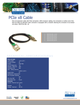
The CYDIO 96HE has a 100-pin, high-density Robinson-Nugent male connector. You can use the CBL 100xx
cable to split the 100 I/O lines into two 50-pin cables (see Figure 2 on page 9).
Board connector pins 1 to 50 are mapped directly to pins 1 to 50 on the CBL 100xx cable's first 50-pin
connector. Pins 51 to 100 are mapped directly to pins 1 to 50 on the second 50-pin connector (pin 51 is mapped
to pin 1, and pin 100 is mapped to pin 50.) A sample CBL 100xx cable configuration is shown in Figure 3 on
page 9.
Caution! When connecting a cable to the board's I/O connector, make sure that the arrow indicating pin 1
on the board connector lines up with the arrow indicating pin 1 on the cable connector. Incorrectly
connected cables can damage the board and the I/O controller.
7

CYDIO 96HE User's Guide Installing the CYDIO 96HE
Connector pin out
Main I/O connector pin out
Signal name Pin
Pin Signal name
GND 100
•
•
50 GND
+5V User Output* 99
•
•
49 +5V User Output*
THIRDPORTC Bit 0 98
•
•
48 FIRSTPORTC Bit 0
THIRDPORTC Bit 1 97
•
•
47 FIRSTPORTC Bit 1
THIRDPORTC Bit 2 96
•
•
46 FIRSTPORTC Bit 2
THIRDPORTC Bit 3 95
•
•
45 FIRSTPORTC Bit 3
THIRDPORTC Bit 4 94
•
•
44 FIRSTPORTC Bit 4
THIRDPORTC Bit 5 93
•
•
43 FIRSTPORTC Bit 5
THIRDPORTC Bit 6 92
•
•
42 FIRSTPORTC Bit 6
THIRDPORTC Bit 7 91
•
•
41 FIRSTPORTC Bit 7
THIRDPORTB Bit 0 90
•
•
40 FIRSTPORTB Bit 0
THIRDPORTB Bit 1 89
•
•
39 FIRSTPORTB Bit 1
THIRDPORTB Bit 2 88
•
•
38 FIRSTPORTB Bit 2
THIRDPORTB Bit 3 87
•
•
37 FIRSTPORTB Bit 3
THIRDPORTB Bit 4 86
•
•
36 FIRSTPORTB Bit 4
THIRDPORTB Bit 5 85
•
•
35 FIRSTPORTB Bit 5
THIRDPORTB Bit 6 84
•
•
34 FIRSTPORTB Bit 6
THIRDPORTB Bit 7 83
•
•
33 FIRSTPORTB Bit 7
THIRDPORTA Bit 0 82
•
•
32 FIRSTPORTA Bit 0
THIRDPORTA Bit 1 81
•
•
31 FIRSTPORTA Bit 1
THIRDPORTA Bit 2 80
•
•
30 FIRSTPORTA Bit 2
THIRDPORTA Bit 3 79
•
•
29 FIRSTPORTA Bit 3
THIRDPORTA Bit 4 78
•
•
28 FIRSTPORTA Bit 4
THIRDPORTA Bit 5 77
•
•
27 FIRSTPORTA Bit 5
THIRDPORTA Bit 6 76
•
•
26 FIRSTPORTA Bit 6
THIRDPORTA Bit 7 75
•
•
25 FIRSTPORTA Bit 7
FOURTHPORTC Bit 0 74
•
•
24 SECONDPORTC Bit 0
FOURTHPORTC Bit 1 73
•
•
23 SECONDPORTC Bit 1
FOURTHPORTC Bit 2 72
•
•
22 SECONDPORTC Bit 2
FOURTHPORTC Bit 3 71
•
•
21 SECONDPORTC Bit 3
FOURTHPORTC Bit 4 70
•
•
20 SECONDPORTC Bit 4
FOURTHPORTC Bit 5 69
•
•
19 SECONDPORTC Bit 5
FOURTHPORTC Bit 6 68
•
•
18 SECONDPORTC Bit 6
FOURTHPORTC Bit 7 67
•
•
17 SECONDPORTC Bit 7
FOURTHPORTB Bit 0 66
•
•
16 SECONDPORTB Bit 0
FOURTHPORTB Bit 1 65
•
•
15 SECONDPORTB Bit 1
FOURTHPORTB Bit 2 64
•
•
14 SECONDPORTB Bit 2
FOURTHPORTB Bit 3 63
•
•
13 SECONDPORTB Bit 3
FOURTHPORTB Bit 4 62
•
•
12 SECONDPORTB Bit 4
FOURTHPORTB Bit 5 61
•
•
11 SECONDPORTB Bit 5
FOURTHPORTB Bit 6 60
•
•
10 SECONDPORTB Bit 6
FOURTHPORTB Bit 7 59
•
•
9 SECONDPORTB Bit 7
FOURTHPORTA Bit 0 58
•
•
8 SECONDPORTA Bit 0
FOURTHPORTA Bit 1 57
•
•
7 SECONDPORTA Bit 1
FOURTHPORTA Bit 2 56
•
•
6 SECONDPORTA Bit 2
FOURTHPORTA Bit 3 55
•
•
5 SECONDPORTA Bit 3
FOURTHPORTA Bit 4 54
•
•
4 SECONDPORTA Bit 4
FOURTHPORTA Bit 5 53
•
•
3 SECONDPORTA Bit 5
FOURTHPORTA Bit 6 52
•
•
2 SECONDPORTA Bit 6
FOURTHPORTA Bit 7 51
•
•
1 SECONDPORTA Bit 7
PCIe slot ↓
* The board has two individual slow blow fuses rated at 1 A. One fuse protects the +5V User Output at pin 49,
and one fuse protects the +5V User Output at pin 99.
8

CYDIO 96HE User's Guide Installing the CYDIO 96HE
Cabling
1
50
2
49
51
100
52
99
10050
511
Key
Key
The red stripe
identifies pin # 1
The red stripe
identifies pin # 51
Cable is labeled
“Pins 51-100”.
Cable is labeled
“Pins 1-50”.
Figure 2. CBL 100xx cable
Caution! When connecting the cable to the board's I/O connector, make sure that the arrow indicating pin 1
on the board connector lines up with the arrow indicating pin 1 on the cable connector. Incorrectly
connected cables can damage the board and the I/O controller.
Digital signal conditioning o
r
50-pin screw terminal board
IN
Digital I/O
pins 51 to 100
IN
100-pin
I/O connecto
r
Digital I/O
pins 1 to 50
Digital signal conditioning o
r
50-pin screw terminal board
CBL 100xx cable
Figure 3. CBL 100xx cable configuration
9

10
Chapter 3
Functional Details
CYERB 24 and CYSSR 24 daisy chain configuration
Many relay and solid-state relay (SSR) racks provide only 24-bits of digital I/O. You can configure the CYERB
24 relay output board and CYSSR 24 I/O module rack in a daisy chain configuration to use all of the digital I/O
bits provided by the CYDIO 96HE board. An example of the daisy chain configuration scheme for each board
is shown below.
The CYDIO 96HE board provides digital I/O in a group of 96 bits. Each of the CBL 100xx cable's 50-pin
connectors provides 48 bits. To use all of the board's 96 digital I/O bits to control relays and/or SSRs, configure
the daisy chain as shown in Figure 4.
CIO-ERB24
or
SSR-Rack24
IN
OUT
CIO-ERB24
or
SSR-Rack24
IN
OUT
CIO-ERB24
or
SSR-Rack24
IN
OUT
CIO-ERB24
or
SSR-Rack24
IN
OUT
C100FF-x Cable
PCIe-DIO96H
Figure 4. CYDIO 96HE to CBL 100xx to relay rack daisy chain cabling
The 24 digital I/O bits on pins 1-24 control the first relay board on the chain. The 24 digital I/O bits on pins
25-50 control the second relay/SSR board on the daisy chain and so on, for up to 100 pins.
82C55 emulation (mode 0)
The CYDIO 96HE emulates the 82C55 chip (mode 0). The 82C55 emulation initializes all ports as inputs on
power-up and reset. A TTL input is a high impedance input. If you connect another TTL input device to the
output, it could be turned on or off every time the board is reset.
To establish a consistent TTL level at power-up, configure each port resistor with InstaCal for either pull-up or
pull-down.
Whenever an 82C55 emulation is powered on or reset, all pins are set to high-impedance input. Based on
standard TTL functionality, these inputs typically float high, and may have enough drive current to turn on
external devices. Consequently, if you have output devices such as solid state relays, they may be switched on
whenever the computer is powered on or reset. To prevent unwanted switching, and to drive all outputs to a
known state after power on or reset, configure each port resistor with InstaCal.
Unconnected inputs are forced to the pull direction
Unconnected inputs will float in the pull direction that is configured for the port with InstaCal (either up/high or
down/low).
CYERB 24
Or
CYSSR 24
CYERB 24
Or
CYSSR 24
CYERB 24
Or
CYSSR 24
CYERB 24
Or
CYSSR 24
CYDIO 96HE
CYDIO 96HE

CYDIO 96HE User's Guide Functional Details
11
Replacing a fuse
The CYDIO 96HE has two individual 1 amp slow blow fuses. One fuse is connected to the +5V User Output at
pin 49, and is labeled
F1 on the board. The second fuse is connected to the +5V User Output at pin 99, and is
labeled
F2 on the board. A spare fuse is installed on the board at location F3. All fuses are secured to the board
with clips for convenient replacement.
A fuse will blow during operation if amperage exceeds 1 amp. If you need to replace a fuse, perform the
following procedure.
1. Pry the center of the fuse from the fuse holder clip.
2. Insert the replacement fuse into the fuse holder clip.
Fuse specifications
Refer to the information below to purchase additional fuses, (or an equivalent), if required:
Manufacturer: LittelFuse®
Series: 452 Slo-Blo®
Part number: 0452001. (Include the period as part of the item number.)
1 amp, 125 volts, 0.225 Ω
http://www.littelfuse.com/part/0452001..html

12
Chapter 4
Specifications
Typical for 25 °C unless otherwise specified.
Specifications in italic text are guaranteed by design.
Digital input / output
Table 1. Digital I/O specifications
Digital type 8255 emulation, Mode 0
Output 74ABT244
Input 74LV373A
Configuration 8 banks of 8, 8 banks of 4, programmable by bank as input or output
Number of I/O 96
Output high 2.0 volts min @ -15 mA
Output low 0.55 volts max @ 64 mA
Input high 2.0 volts min, 5.5 volts absolute max
Input low 0.8 volts max, -0.5 volts absolute min
Power-up / reset state
Input mode (10 kΩ impedance from pull-up or pull-down)
Pull-up/pull-down resistors
EEPROM stored - Software Programmable driven by 74ACT244 through
10 kΩ bussed resistor networks (shipped in the pull-up state)
Power Consumption
Table 2. Power consumption specifications
+3.3 V Operating (bus) 484 mA max. (405 mA typ.)
+5 V Operating (Molex) 1.74 A max. (54 mA typ. no load)
+5 V
User Output (Molex) 1 A max. per +5 V User Output (pins 49 & 99, protected with 1 A slow blow fuse)
+5 V User Output Fuse 1 A Littelfuse ® Slo-Blo ® Fuse P/N: 0452001. or equivalent
Environmental
Table 3. Environmental specifications
Operating temperature range 0 to 50 °C
Storage temperature range -35 to 80 °C
Humidity 0 to 90% non-condensing
Mechanical
Table 4. Mechanical specifications
Card dimensions 167.6 mm (L) x 106.6 mm (H) x 14.48 mm (W)
General
Table 5. General Specifications
Bus Type PCI Express 1.0a
Bus Width x1 lane PCI Express

CYDIO 96HE User's Guide Specifications
Main connector and pin out
Table 6. Main connector specifications
Connector type 100-pin, high-density
Compatible cables CBL 100xx
Compatible accessory products CYSTP 50 (two devices are required)
STA 100
CYSTP 502E
CYERB 24
CYERB 24S
CYERB 48
CYERB 48S
CYSSR 24
CYSSR 48
Table 7. Main connector pin out
Pin Signal name Pin Signal name
100 GND 50 GND
99 +5V User Output* 49 +5V User Output*
98 THIRDPORTC Bit 0 48 FIRSTPORTC Bit 0
97 THIRDPORTC Bit 1 47 FIRSTPORTC Bit 1
96 THIRDPORTC Bit 2 46 FIRSTPORTC Bit 2
95 THIRDPORTC Bit 3 45 FIRSTPORTC Bit 3
94 THIRDPORTC Bit 4 44 FIRSTPORTC Bit 4
93 THIRDPORTC Bit 5 43 FIRSTPORTC Bit 5
92 THIRDPORTC Bit 6 42 FIRSTPORTC Bit 6
91 THIRDPORTC Bit 7 41 FIRSTPORTC Bit 7
90 THIRDPORTB Bit 0 40 FIRSTPORTB Bit 0
89 THIRDPORTB Bit 1 39 FIRSTPORTB Bit 1
88 THIRDPORTB Bit 2 38 FIRSTPORTB Bit 2
87 THIRDPORTB Bit 3 37 FIRSTPORTB Bit 3
86 THIRDPORTB Bit 4 36 FIRSTPORTB Bit 4
85 THIRDPORTB Bit 5 35 FIRSTPORTB Bit 5
84 THIRDPORTB Bit 6 34 FIRSTPORTB Bit 6
83 THIRDPORTB Bit 7 33 FIRSTPORTB Bit 7
82 THIRDPORTA Bit 0 32 FIRSTPORTA Bit 0
81 THIRDPORTA Bit 1 31 FIRSTPORTA Bit 1
80 THIRDPORTA Bit 2 30 FIRSTPORTA Bit 2
78 THIRDPORTA Bit 3 29 FIRSTPORTA Bit 3
78 THIRDPORTA Bit 4 28 FIRSTPORTA Bit 4
77 THIRDPORTA Bit 5 27 FIRSTPORTA Bit 5
76 THIRDPORTA Bit 6 26 FIRSTPORTA Bit 6
75 THIRDPORTA Bit 7 25 FIRSTPORTA Bit 7
74 FOURTHPORTC Bit 0 24 SECONDPORTC Bit 0
73 FOURTHPORTC Bit 1 23 SECONDPORTC Bit 1
72 FOURTHPORTC Bit 2 22 SECONDPORTC Bit 2
71 FOURTHPORTC Bit 3 21 SECONDPORTC Bit 3
70 FOURTHPORTC Bit 4 20 SECONDPORTC Bit 4
69 FOURTHPORTC Bit 5 19 SECONDPORTC Bit 5
68 FOURTHPORTC Bit 6 18 SECONDPORTC Bit 6
67 FOURTHPORTC Bit 7 17 SECONDPORTC Bit 7
66 FOURTHPORTB Bit 0 16 SECONDPORTB Bit 0
65 FOURTHPORTB Bit 1 15 SECONDPORTB Bit 1
64 FOURTHPORTB Bit 2 14 SECONDPORTB Bit 2
63 FOURTHPORTB Bit 3 13 SECONDPORTB Bit 3
62 FOURTHPORTB Bit 4 12 SECONDPORTB Bit 4
61 FOURTHPORTB Bit 5 11 SECONDPORTB Bit 5
13

CYDIO 96HE User's Guide Specifications
14
60 FOURTHPORTB Bit 6 10 SECONDPORTB Bit 6
59 FOURTHPORTB Bit 7 9 SECONDPORTB Bit 7
58 FOURTHPORTA Bit 0 8 SECONDPORTA Bit 0
57 FOURTHPORTA Bit 1 7 SECONDPORTA Bit 1
56 FOURTHPORTA Bit 2 6 SECONDPORTA Bit 2
55 FOURTHPORTA Bit 3 5 SECONDPORTA Bit 3
54 FOURTHPORTA Bit 4 4 SECONDPORTA Bit 4
53 FOURTHPORTA Bit 5 3 SECONDPORTA Bit 5
52 FOURTHPORTA Bit 6 2 SECONDPORTA Bit 6
51 FOURTHPORTA Bit 7 1 SECONDPORTA Bit 7
* Protected by individual slow blow fuses rated at 1 A.

CyberResearch
®
Digital I/O
CYDIO 9HE
Product Service
Diagnosis and Debug
CyberResearch, Inc. maintains technical support lines staffed by experienced
Applications Engineers and Technicians. There is no charge to call and we will
return your call promptly if it is received while our lines are busy. Most problems
encountered with data acquisition products can be solved over the phone. Signal
connections and programming are the two most common sources of difficulty.
CyberResearch support personnel can help you solve these problems, especially if
you are prepared for the call.
To ensure your call’s overall success and expediency:
1) Have the phone close to the PC so you can conveniently and quickly take
action that the Applications Engineer might suggest.
2) Be prepared to open your PC, remove boards, report back-switch or jumper
settings, and possibly change settings before reinstalling the modules.
3) Have a volt meter handy to take measurements of the signals you are trying
to measure as well as the signals on the board, module, or power supply.
4) Isolate problem areas that are not working as you expected.
5) Have the source code to the program you are having trouble with available
so that preceding and prerequisite modes can be referenced and discussed.
6) Have the manual at hand. Also have the product’s utility disks and any
other relevant disks nearby so programs and version numbers can be
checked.
Preparation will facilitate the diagnosis procedure, save you time, and avoid
repeated calls. Here are a few preliminary actions you can take before you call
which may solve some of the more common problems:
1) Check the PC-bus power and any power supply signals.
2) Check the voltage level of the signal between SIGNAL HIGH and
SIGNAL LOW, or SIGNAL+ and SIGNAL– . It CANNOT exceed the full
scale range of the board.
3) Check the other boards in your PC or modules on the network for address
and interrupt conflicts.
4) Refer to the example programs as a baseline for comparing code.
CyberResearch, Inc. 15
25 Business Park Drive P: (203) 643-5000; F: (203) 643-5001
Branford, CT USA www.cyberresearch.com

CYDIO 9HE CyberResearch
®
Digital I/O
Intentionally Blank
16 ©Copyright 2009 CyberResearch, Inc.
/