Page is loading ...


SharpShooter
®
with Rate Sync™ Product Manual 1
CONTENTS
INTRODUCTION . . . . . . . . . . . . . . . . . . . . . . . . . . . . . . . . . . . . . . . . . . . . . . . . . . . . . . . . . . . 5
SAFETY . . . . . . . . . . . . . . . . . . . . . . . . . . . . . . . . . . . . . . . . . . . . . . . . . . . . . . . . . . . . . . . . . . 7
Safe Operation Is The Operator’s Responsibility . . . . . . . . . . . . . . . . . . . . . . . . . . . . . . . . 7
Personal Safety . . . . . . . . . . . . . . . . . . . . . . . . . . . . . . . . . . . . . . . . . . . . . . . . . . . . . . . . . . 8
Health & Safety . . . . . . . . . . . . . . . . . . . . . . . . . . . . . . . . . . . . . . . . . . . . . . . . . . . . . . . . . . 9
Chemical Safety . . . . . . . . . . . . . . . . . . . . . . . . . . . . . . . . . . . . . . . . . . . . . . . . . . . . . . . . . 9
Use Safety Rules . . . . . . . . . . . . . . . . . . . . . . . . . . . . . . . . . . . . . . . . . . . . . . . . . . . . . . . . . 9
FIRE PREVENTION . . . . . . . . . . . . . . . . . . . . . . . . . . . . . . . . . . . . . . . . . . . . . . . . . . . . . . . . 10
Electrical . . . . . . . . . . . . . . . . . . . . . . . . . . . . . . . . . . . . . . . . . . . . . . . . . . . . . . . . . . . . . . 10
Welding . . . . . . . . . . . . . . . . . . . . . . . . . . . . . . . . . . . . . . . . . . . . . . . . . . . . . . . . . . . . . . . 10
Fire Extinguishers . . . . . . . . . . . . . . . . . . . . . . . . . . . . . . . . . . . . . . . . . . . . . . . . . . . . . . . 10
OPERATION . . . . . . . . . . . . . . . . . . . . . . . . . . . . . . . . . . . . . . . . . . . . . . . . . . . . . . . . . . . . . . 11
SharpShooter with Rate Sync (SSRS Display) . . . . . . . . . . . . . . . . . . . . . . . . . . . . . . . . . 11
Menu Items . . . . . . . . . . . . . . . . . . . . . . . . . . . . . . . . . . . . . . . . . . . . . . . . . . . . . . . . . . . . 12
Operator Controls . . . . . . . . . . . . . . . . . . . . . . . . . . . . . . . . . . . . . . . . . . . . . . . . . . . . . . . 20
Spraying Without the Sharpshooter with Rate Sync System . . . . . . . . . . . . . . . . . . . . . . . 22
Tip Selection and Capacities . . . . . . . . . . . . . . . . . . . . . . . . . . . . . . . . . . . . . . . . . . . . . . . 23
Blended Pulse Tip Chart . . . . . . . . . . . . . . . . . . . . . . . . . . . . . . . . . . . . . . . . . . . . . . . . . . 24
Technical Bulletin - July 11, 2001 (Revised April 12, 2006) . . . . . . . . . . . . . . . . . . . . . . . 26
MAINTENANCE . . . . . . . . . . . . . . . . . . . . . . . . . . . . . . . . . . . . . . . . . . . . . . . . . . . . . . . . . . . 29
Inspecting the Spray System . . . . . . . . . . . . . . . . . . . . . . . . . . . . . . . . . . . . . . . . . . . . . . . 29
Cleaning The Spray System . . . . . . . . . . . . . . . . . . . . . . . . . . . . . . . . . . . . . . . . . . . . . . . 29
PARTS IDENTIFICATION . . . . . . . . . . . . . . . . . . . . . . . . . . . . . . . . . . . . . . . . . . . . . . . . . . . 31
SharpShooter with Rate Sync (SSRS Display) . . . . . . . . . . . . . . . . . . . . . . . . . . . . . . . . . 31
Power Hub . . . . . . . . . . . . . . . . . . . . . . . . . . . . . . . . . . . . . . . . . . . . . . . . . . . . . . . . . . . . . 31
Valve Driver . . . . . . . . . . . . . . . . . . . . . . . . . . . . . . . . . . . . . . . . . . . . . . . . . . . . . . . . . . . . 32
Pressure Sensor . . . . . . . . . . . . . . . . . . . . . . . . . . . . . . . . . . . . . . . . . . . . . . . . . . . . . . . . 32
Harness, Pressure Sensor . . . . . . . . . . . . . . . . . . . . . . . . . . . . . . . . . . . . . . . . . . . . . . . . 33
Harness, Pigtail (SSRS Display) . . . . . . . . . . . . . . . . . . . . . . . . . . . . . . . . . . . . . . . . . . . . 33
Extension Harness (SSRS Display) . . . . . . . . . . . . . . . . . . . . . . . . . . . . . . . . . . . . . . . . . 33
Serial Extension Cable . . . . . . . . . . . . . . . . . . . . . . . . . . . . . . . . . . . . . . . . . . . . . . . . . . . 33
Extension Harnesses (Boom) . . . . . . . . . . . . . . . . . . . . . . . . . . . . . . . . . . . . . . . . . . . . . . 34
Boom Shutoff Adapter . . . . . . . . . . . . . . . . . . . . . . . . . . . . . . . . . . . . . . . . . . . . . . . . . . . . 34
Y-Adapters . . . . . . . . . . . . . . . . . . . . . . . . . . . . . . . . . . . . . . . . . . . . . . . . . . . . . . . . . . . . . 35
Nozzle Valve Assembly . . . . . . . . . . . . . . . . . . . . . . . . . . . . . . . . . . . . . . . . . . . . . . . . . . . 35
Nozzle Harnesses . . . . . . . . . . . . . . . . . . . . . . . . . . . . . . . . . . . . . . . . . . . . . . . . . . . . . . . 36
Nozzle Alternator Harness . . . . . . . . . . . . . . . . . . . . . . . . . . . . . . . . . . . . . . . . . . . . . . . . . 37
Power Harness . . . . . . . . . . . . . . . . . . . . . . . . . . . . . . . . . . . . . . . . . . . . . . . . . . . . . . . . . 37
Circuit Breaker Kit (80A) . . . . . . . . . . . . . . . . . . . . . . . . . . . . . . . . . . . . . . . . . . . . . . . . . . 37
Power Hub Cover . . . . . . . . . . . . . . . . . . . . . . . . . . . . . . . . . . . . . . . . . . . . . . . . . . . . . . . 37
Packard and Deutsch Plugs . . . . . . . . . . . . . . . . . . . . . . . . . . . . . . . . . . . . . . . . . . . . . . . 38
SharpShooter with Rate Sync Product Manual . . . . . . . . . . . . . . . . . . . . . . . . . . . . . . . . . 38

2 SharpShooter
®
with Rate Sync™ Product Manual
Power Disconnect Kit (Optional) . . . . . . . . . . . . . . . . . . . . . . . . . . . . . . . . . . . . . . . . . . . . 38
Pressure Sensor Breakout Harness . . . . . . . . . . . . . . . . . . . . . . . . . . . . . . . . . . . . . . . . . 38
Installation Kit . . . . . . . . . . . . . . . . . . . . . . . . . . . . . . . . . . . . . . . . . . . . . . . . . . . . . . . . . . 39
SharpShooter with Rate Sync Parts List . . . . . . . . . . . . . . . . . . . . . . . . . . . . . . . . . . . . . . 40
Base Kit . . . . . . . . . . . . . . . . . . . . . . . . . . . . . . . . . . . . . . . . . . . . . . . . . . . . . . . . . . . . . . . 41
General Layout Example . . . . . . . . . . . . . . . . . . . . . . . . . . . . . . . . . . . . . . . . . . . . . . . . . . 42
SHARPSHOOTER WITH RATE SYNC SYSTEM . . . . . . . . . . . . . . . . . . . . . . . . . . . . . . . . . 45
SharpShooter with Rate Sync Kit . . . . . . . . . . . . . . . . . . . . . . . . . . . . . . . . . . . . . . . . . . . 45
SHARPSHOOTER WITH RATE SYNC INSTALLATION OVERVIEW . . . . . . . . . . . . . . . . . . 46
SharpShooter with Rate Sync Installation Overview Steps 1 - 11 . . . . . . . . . . . . . . . . . . . 46
SHARPSHOOTER WITH RATE SYNC INSTALLATION DETAIL . . . . . . . . . . . . . . . . . . . . . 48
SharpShooter with Rate Sync (SSRS Display) . . . . . . . . . . . . . . . . . . . . . . . . . . . . . . . . . 48
Harness Pigtail (SSRS Display) . . . . . . . . . . . . . . . . . . . . . . . . . . . . . . . . . . . . . . . . . . . . . 48
Serial Extension . . . . . . . . . . . . . . . . . . . . . . . . . . . . . . . . . . . . . . . . . . . . . . . . . . . . . . . . . 48
Power Hub . . . . . . . . . . . . . . . . . . . . . . . . . . . . . . . . . . . . . . . . . . . . . . . . . . . . . . . . . . . . . 49
Pressure Sensor . . . . . . . . . . . . . . . . . . . . . . . . . . . . . . . . . . . . . . . . . . . . . . . . . . . . . . . . 49
Harness Pressure Sensor . . . . . . . . . . . . . . . . . . . . . . . . . . . . . . . . . . . . . . . . . . . . . . . . . 50
Boom Section Box Components . . . . . . . . . . . . . . . . . . . . . . . . . . . . . . . . . . . . . . . . . . . . 50
Boom Shutoff Adapter . . . . . . . . . . . . . . . . . . . . . . . . . . . . . . . . . . . . . . . . . . . . . . . . . . . . 53
Harness Extension (SSRS Display) . . . . . . . . . . . . . . . . . . . . . . . . . . . . . . . . . . . . . . . . . . 54
Harness Power . . . . . . . . . . . . . . . . . . . . . . . . . . . . . . . . . . . . . . . . . . . . . . . . . . . . . . . . . 54
Circuit Breaker . . . . . . . . . . . . . . . . . . . . . . . . . . . . . . . . . . . . . . . . . . . . . . . . . . . . . . . . . . 55
Power Disconnect Kit (Optional) . . . . . . . . . . . . . . . . . . . . . . . . . . . . . . . . . . . . . . . . . . . . 56
Special Installation Instructions . . . . . . . . . . . . . . . . . . . . . . . . . . . . . . . . . . . . . . . . . . . . . 57
SharpShooter with Rate Sync Installation Tips . . . . . . . . . . . . . . . . . . . . . . . . . . . . . . . . . 60
INSTALLATION SYSTEM TEST . . . . . . . . . . . . . . . . . . . . . . . . . . . . . . . . . . . . . . . . . . . . . . . 61
SharpShooter with Rate Sync (SSRS Display) Check . . . . . . . . . . . . . . . . . . . . . . . . . . . 61
PRESSURE TUNING WITH PID PARAMETERS . . . . . . . . . . . . . . . . . . . . . . . . . . . . . . . . . . 63
SharpShooter with Rate Sync (SSRS Display) Data Logging Procedure . . . . . . . . . . . . . 63
SHARPSHOOTER WITH RATE SYNC TROUBLESHOOTING . . . . . . . . . . . . . . . . . . . . . . . 65
Service - Recommended Guidelines . . . . . . . . . . . . . . . . . . . . . . . . . . . . . . . . . . . . . . . . . 65
Baseline Service Checks . . . . . . . . . . . . . . . . . . . . . . . . . . . . . . . . . . . . . . . . . . . . . . . . . . 65
Swapping Components . . . . . . . . . . . . . . . . . . . . . . . . . . . . . . . . . . . . . . . . . . . . . . . . . . . 65
Fuses . . . . . . . . . . . . . . . . . . . . . . . . . . . . . . . . . . . . . . . . . . . . . . . . . . . . . . . . . . . . . . . . . 66
Circuit Breaker . . . . . . . . . . . . . . . . . . . . . . . . . . . . . . . . . . . . . . . . . . . . . . . . . . . . . . . . . . 66
Nozzle Valve Servicing . . . . . . . . . . . . . . . . . . . . . . . . . . . . . . . . . . . . . . . . . . . . . . . . . . . 66
Nozzle Valve Parts Identification . . . . . . . . . . . . . . . . . . . . . . . . . . . . . . . . . . . . . . . . . . . . 68
Nozzle Valve Diagnostics . . . . . . . . . . . . . . . . . . . . . . . . . . . . . . . . . . . . . . . . . . . . . . . . . 69
Wet Tests . . . . . . . . . . . . . . . . . . . . . . . . . . . . . . . . . . . . . . . . . . . . . . . . . . . . . . . . . . . . . . 69
Symptom Troubleshooting Chart . . . . . . . . . . . . . . . . . . . . . . . . . . . . . . . . . . . . . . . . . . . . 71
SharpShooter with Rate Sync (SSRS Display) . . . . . . . . . . . . . . . . . . . . . . . . . . . . . . . . . 73
Power Hub Pinout Identification . . . . . . . . . . . . . . . . . . . . . . . . . . . . . . . . . . . . . . . . . . . . . 74
System Load Capacity Check . . . . . . . . . . . . . . . . . . . . . . . . . . . . . . . . . . . . . . . . . . . . . . 75
Valve Driver Voltage Check . . . . . . . . . . . . . . . . . . . . . . . . . . . . . . . . . . . . . . . . . . . . . . . . 75

SharpShooter
®
with Rate Sync™ Product Manual 3
Pressure Sensor Signal Test . . . . . . . . . . . . . . . . . . . . . . . . . . . . . . . . . . . . . . . . . . . . . . .76
Pressure Sensor Input Power Check . . . . . . . . . . . . . . . . . . . . . . . . . . . . . . . . . . . . . . . . .77
Pulse Circuit Test . . . . . . . . . . . . . . . . . . . . . . . . . . . . . . . . . . . . . . . . . . . . . . . . . . . . . . . .78
Boom Shutoff and Run / Hold Signal Test . . . . . . . . . . . . . . . . . . . . . . . . . . . . . . . . . . . . .81
Programming the SSRS Display . . . . . . . . . . . . . . . . . . . . . . . . . . . . . . . . . . . . . . . . . . . . .82
RATE CONTROLLER TROUBLESHOOTING . . . . . . . . . . . . . . . . . . . . . . . . . . . . . . . . . . . . .83
Basic Rate Controller . . . . . . . . . . . . . . . . . . . . . . . . . . . . . . . . . . . . . . . . . . . . . . . . . . . . .83
WARRANTY POLICY . . . . . . . . . . . . . . . . . . . . . . . . . . . . . . . . . . . . . . . . . . . . . . . . . . . . . . .85
SERVICE CONTACT INFORMATION . . . . . . . . . . . . . . . . . . . . . . . . . . . . . . . . . . . . . . . . . . .87

4 SharpShooter
®
with Rate Sync™ Product Manual

Application Systems for Professionals
www.CapstanAg.com
SharpShooter
®
with Rate Sync™ Product Manual 5
INTRODUCTION
INTRODUCTION
Congratulations! You are now part of the Capstan Ag Systems, Inc. precision application team, utilizing Blended
Pulse™ - a technology providing many features to assist in your spraying process!
Blended Pulse™ technology is an innovative process utilizing Pulse Width Modulation to enhance your spraying
experience. With Blended Pulse™ you have a spray system with the ability to reduce drift potential, decrease waste,
and lessen time spent in the field.
Your SharpShooter
®
with Rate Sync™ system is designed to solve many of the spraying challenges experienced
today. The features allow a more consistent application over wide speed ranges and frequent speed changes.
Working with your rate controller, SharpShooter
®
with Rate Sync™ automatically corrects rate and pressure, keeping
you consistently on target. The SharpShooter
®
with Rate Sync™ Display provides you with visual and audible
indicators of your application. Audible alarms sound when application variables are inconsistent with your
predetermined settings. With a range of menu settings allowing customized experiences in the field, you have the
ability to enhance your application.
The Capstan team is excited to partner with you in your precision application operation. As an owner of a Capstan
spray system, a network of experienced professionals are available in your region to provide informative technical
support regarding your SharpShooter
®
with Rate Sync™ spray system. To locate your nearest Capstan Dealer,
Capstan Field Marketer or Field Technical Specialist please contact Capstan Ag Systems, Inc. at:
Capstan Ag Systems, Inc.
4225 SW Kirklawn Ave.
Topeka, KS 66609
(785) 232-4477 - Headquarters
(785) 232-7799 - Fax
(855) 628-7722 - Toll-Free
prodsupport@capstanag.com
www.capstanag.com
NOTE: This document and the information provided are the property of Capstan Ag Systems, Inc. and may
only be used as authorized by Capstan Ag Systems, Inc.

6 SharpShooter
®
with Rate Sync™ Product Manual
Capstan Ag Systems
855-628-7722

SAFETY
Application Systems for Professionals
www.CapstanAg.com
SharpShooter
®
with Rate Sync™ Product Manual 7
SAFETY
Safe Operation Is The Operator’s Responsibility
• Make sure that all personnel have read this manual,
and thoroughly understand safe and correct
installation, operation and maintenance
procedures.
• It is important for all individuals working with
fertilizer to understand the potential risks,
necessary safety precautions, and proper response
in the event of accidental contact.
This symbol with a warning statement means:
“Warning, be alert! Your safety is involved!”
Carefully read the message that follows.
Safety Alert Symbol
The signal word DANGER on the machine and in
the manuals indicates a hazardous situation
which, if not avoided, may result in death or
serious injury.
The signal word CAUTION on the machine and in
the manuals indicates a potentially hazardous
situation which, if not avoided, may result in
minor or moderate injury. It may also be used to
alert against unsafe practices.
The signal word WARNING on the machine and in
the manuals indicates a potentially hazardous
situation which, if not avoided, may result in death
or serious injury.
This notice identifies procedures which should be
followed to avoid damage to the machine.

8 SharpShooter
®
with Rate Sync™ Product Manual
Capstan Ag Systems
855-628-7722
SAFETY CONT.
Personal Safety
• Use appropriate hand protection when hands are
exposed to hazards such as: those from skin
absorption of harmful substances, severe cuts or
lacerations, severe abrasions, punctures, chemical
burns, thermal burns, and harmful temperature
extremes.
• Installation should be performed by a person who is
familiar with all local, state, and federal laws.
Always wear proper protective equipment and
use extreme caution when bleeding the sprayer
system.
Working with sprayer equipment can be
dangerous, so the proper hand and eye
protection should be used at all times.
Sprayer lines may be pressurized. Relieve
pressure before removing pressure sensor or
pressure sensor lines.
Before removal or installation of nozzle valves,
make sure that the pressure has been released
from the sprayer lines.
Instructions are necessary before operating or
servicing system. Read and understand the
machine’s Operator Manual and this Product
Manual. Follow warnings and instructions in the
manuals when making repairs, adjustments or
servicing. Check for correct function after
adjustments, repairs or service. Untrained operators
and failure to follow instructions may cause injury
or death.
The spray tank and system should be emptied of
chemical mixture and flushed with clean water
before servicing the spray system or spray
components. Clean the machine of all chemical
residue before servicing.

SAFETY
Application Systems for Professionals
www.CapstanAg.com
SharpShooter
®
with Rate Sync™ Product Manual 9
SAFETY CONT.
Health & Safety
• Sealant materials should be strictly applied in
accordance with the manufacturer's instructions.
• Only an approved type of sealant, gasket or tape
should be used.
Chemical Safety
• Always read the label before using chemicals.
Follow the instructions from the chemical
manufacturer on how to select, use and handle
each chemical. Note protection information each
time before opening the container.
• If written warnings cannot be understood by
workers, verbal warnings should be given.
• Do not spill chemicals on skin or clothing. If
chemicals are spilled, follow the instructions
provided by the chemical manufacturer.
• The spray tank and system should be emptied of
chemical mixture and flushed with clean water
before servicing the spray system or spray
components. Clean the machine of all chemical
residue before servicing.
• Avoid inhaling chemicals. When directed to do so
on the chemical label, wear protective clothing, face
shield or goggles.
• Never smoke while spraying or handling chemicals.
• When spraying areas containing livestock or pets,
cover food and water containers.
• If symptoms of illness occur during or shortly after
spraying, immediately call a physician or go to a
hospital.
• Follow the label’s directions and advice to keep the
residues on edible portions of plants within the limits
permitted by law.
• Keep chemicals out of the reach of children, pets
and unauthorized personnel. Store chemicals
outside of the home, away from food and feed, and
lock them in a secure area.
• Keep bystanders away from spray drift.
• Unless the manufacturer instructs otherwise, store
chemicals in their original containers and keep the
containers tightly closed. Read labels for hazards
about chemical reactions with certain types of
metals.
• Always dispose of empty containers according to
the manufacturer’s directions.
Use Safety Rules
• Read and follow instructions on the equipment and
in the equipment’s Operation & Maintenance
Manual before operating.
• In addition to the design and configuration of
equipment, hazard control and accident prevention
are dependent upon the awareness, concern,
prudence and proper training of personnel involved
in the operation, transport, maintenance and
storage of equipment.
• Make sure all the equipment controls are in the
NEUTRAL position before operating the equipment.
• Operate the equipment according to the Operation
& Maintenance Manual.
• DO NOT permit personnel to be in the work area
when operating the equipment.
• DO NOT modify equipment.
• DO NOT make any adjustments or repairs on the
equipment while the engine is running.
• Keep shields and guards in place. Replace if
damaged.

10 SharpShooter
®
with Rate Sync™ Product Manual
Capstan Ag Systems
855-628-7722
FIRE PREVENTION
Electrical
Check all electrical wiring and connections for damage.
Keep the battery terminals clean and tight. Repair or
replace any damaged part or wires that are loose or
frayed.
Battery gas can explode and cause serious injury. Use
the procedure in the Operation & Maintenance Manual
for connecting the battery and for jump starting. Do not
jump start or charge a frozen or damaged battery.
Keep any open flames or sparks away from batteries.
Do not smoke in battery charging area.
Welding
Always clean the equipment, disconnect the battery,
and all component wiring before welding. Cover rubber
hoses, battery and all other flammable parts. Keep a
fire extinguisher near the equipment when welding.
Have good ventilation when welding or grinding
painted parts. Wear dust mask when grinding painted
parts. Toxic dust or gas can be produced.
Dust generated from repairing nonmetallic parts can be
flammable or explosive. Repair such components in a
well ventilated area away from open flames or sparks.
Fire Extinguishers
Know where fire extinguishers and first aid kits are
located and how to use them. Inspect the fire
extinguisher and service the fire extinguisher regularly.
Obey the recommendations on the instructions plate.

Application Systems for Professionals
www.CapstanAg.com
SharpShooter
®
with Rate Sync™ Product Manual 11
OPERATION
OPERATION
SharpShooter with Rate Sync (SSRS Display)
Figure 1
The SSRS Display [Figure 1] has five buttons to
navigate and control the system. A screen on the
SSRS Display interface provides immediate
information and easy access to the menu items.
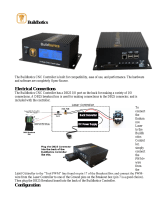
Figure 2
Connections on the back of the SSRS Display [Figure
2] include the main connection port, a gps connection
port and diagnostic connection port.
Power Button - Press the power button to turn on the
SSRS Display. The system defaults to manual mode
each time it is powered up.
With the SSRS Display turned OFF, the sprayer will
only operate as a conventional rate controller. The
Nozzle Solenoids work as an electric On/Off drip check
and work with the boom section On/Off switches.
NOTE: Spraying in the OFF mode will require
selecting different tips.
Menu Button - The menu button is used to enter and
exit the menu list. Press menu button to enter the menu
list pages, use the increase/decrease buttons to
navigate the menu list highlighting the desired field.
Press the menu button to enter desired selection. To
exit menu structure, highlight the exit menu line and
press the menu button.
Auto/Manual Button - Manual mode is the default
mode at power up. Manual mode will pulse nozzle
valves at the duty cycle percentage selected by the
increase/decrease buttons. The Manual mode is used
in the event that the SSRS Display fails to
automatically control pressure. It is not necessary to
change tips.
Manual Mode can also be used to close all nozzle
valves. By toggling down to 10% duty cycle, then
pressing decrease once more. This will close all
solenoids and the diagnostic readout will show “OFF”.
NOTE: In the Manual mode the increase/decrease
buttons act like an electronic rotary nozzle
body with an “infinite” number of tips that
can be selected by the operator.
Automatic mode is the standard operating mode for the
SharpShooter with Rate Sync system. In Auto mode
the SSRS Display will automatically work to maintain
an operator - set target pressure. It does this by pulsing
the nozzle valves at a duty cycle percentage controlled
by the target pressure. Activate the automatic pressure
control by pressing the auto/manual button. The LED
light behind auto/manual button will illuminate when
auto mode is selected.
Increase/Decrease Buttons -
1. Manually select duty cycle percentage, or effective
tips size in Manual mode, or
2. Set target pressure in Auto mode letting the SSRS
Display determine the duty cycle, or in other terms,
the "effective tip" size required.
3. Navigate up and down in menu structure.
Manual
(Effective Tip
Size)
Actual
Pressure
Readout
Auto/Manual
Button
(press for Auto)
Auto
(Target
Pressure)
Duty Cycle
Readout
Area
Menu Button
(enter/exit)
Diagnostic
Readout Area
Power Button
(on/off)
Increase
Button
(toggle up)
Decrease
Button
(toggle down)
Main
Connection
GPS
Connection
Diagnostic
Connection

12 SharpShooter
®
with Rate Sync™ Product Manual
Capstan Ag Systems
855-628-7722
OPERATION CONT.
Other Display Features
Display Screen - Is a real time readout of the
SharpShooter with Rate Sync system operation.
Actual pressure, effective tip size, and duty cycle are
displayed in the Manual mode. Actual pressure, target
pressure and duty cycle appear in the AUTO mode. A
diagnostics readout area appears in both modes.
Figure 3
Indicator Lights and Sounds - The SSRS Display
indicator lights are located behind the Power button
and Auto/Manual button.
When the SSRS Display is powered on, the indicator
light behind the power button (Item 1) [Figure 3] will
appear constant. This signals a properly operating
system.
The indicator light behind the Auto/Manual button (Item
2) will be off when in manual mode (also read out in
center of screen). When Auto mode (Item 3) [Figure 3]
is selected, the indicator light will turn on and screen
readout will change to show target pressure.
The SSRS Display includes audible and visual alarms.
The audible alarms are an accessible menu item.
Visual alarms include a readout area in the lower right
hand portion of the screen and a flashing light behind
the power button.
The alarm readout will appear and the power button
light will flash once per second when the following
appear.
1. Pressor Sensor Error - Present when there is no
pressure acting on the sensor. Could also be
pressure above or below the limits of the pressure
sensor.
2. Minimum Duty Cycle - Appears when the
minimum duty cycle value is experienced.
3. Maximum Duty Cycle - Appears when the
maximum duty cycle value is experienced.
4. No GPS - Will appear when the Rate Sync is
functioning and no GPS values are being received
by the SSRS Display. This error will not appear
when Rate Sync is set to off.
5. No GPS VTG - Shows that the SSRS Display is
receiving some GPS signals but not the necessary
VTG signal.
6. Low Pressure Shutoff - When the Low Pressure
Shutoff menu setting is 8 psi, this readout will
appear when the psi drops below 8 psi. At this point
the nozzle valves will close. Nozzle valves will open
and the readout will clear when psi increases to at
least 12 psi.
Menu Items
The Menu button doubles as enter/exit through all
menu items. To enter main menu press the menu
button. To exit main menu scroll up/down with the
arrow keys to highlight line 15 Exit Menu
, then press
menu button.
Figure 4
Main menu screen, two pages, [Figure 4] shows all the
menu items on left and the current value of each on
right.
1
2
3

Application Systems for Professionals
www.CapstanAg.com
SharpShooter
®
with Rate Sync™ Product Manual 13
OPERATION
OPERATION CONT.
Menu Items Cont.
In each specific menu selection item screen, default
value and current value are both listed on the left side
of the screen. See [Figure 5] as an example.
Range of selection parameters is called out on the
bottom of the screen and selection choices are located
on the right.
To choose a new parameter in any menu, scroll up/
down with the arrow keys highlighting the desired
selection, then press the menu button to exit that
screen. Your selection will now be the value on the
right side of the main menu screen. Reference [Figure
4].
Specific Menu Items -
Line 1 - Backlight
Figure 5
Backlight allows choices of LCD screen brightness and
backlight behind the keypad for low light conditions
[Figure 5].
Range: 1 - 5 (Dimmest to Brightest)
When selections 1 and 2 are active (low ambient light
conditions) the keypad buttons become back-lit.
Line 2 - Alarm Volume
Figure 6
Alarm volume menu offers personalization of the alarm
function. One can choose to deactivate the alarm or a
variety of volumes [Figure 6].
Range: 1 - 5 (Quiet to Loudest)
Line 3 - Spray Tip Size
Figure 7
It is important to choose your Spray Tip Size in the
SSRS Display menu for the Rate Sync to function
properly [Figure 7].
Range: 01 - 20

14 SharpShooter
®
with Rate Sync™ Product Manual
Capstan Ag Systems
855-628-7722
OPERATION CONT.
Line 4 - System Gain
Figure 8
System Gain is the first pressure control parameter in
the SSRS Display menu system. System Gain
changes the total response of system according to the
same ratio between the individual P Gain and I Gain
values. It is the first menu item to utilize when tuning
the pressure control [Figure 8].
Increasing the System Gain makes the SharpShooter
with Rate Sync system react faster to pressure
changes.
Decreasing System Gain makes the SharpShooter with
Rate Sync system react slower to pressure changes.
Range: 1 – 14 (slow to fast)
Recommended Starting Value = 9
Line 5 - P Gain
Figure 9
P (Proportional) gain is the second pressure tuning
parameter in the SSRS Display menu. Proportional
gain determines the initial speed at which SSRS
Display drives the duty cycle toward the target value.
Stabilize an oscillating system by selecting a lower
number. Speed up a sluggish system by selecting a
higher number [Figure 9].
Range: 2.0 – 8.5 (slow to fast)
Recommended Starting Value = 5
Line 6 - I Gain
Figure 10
I (Integral) Gain, the third pressure tuning parameter in
the SSRS Display, determines the acceleration driving
duty cycle to the target value. To stabilize an oscillating
system, use a lower number. To speed up a sluggish
system, use a higher number [Figure 10].
Range: 0.05 – 0.35 (slow to fast)
Recommended Starting Value = 0.15

Application Systems for Professionals
www.CapstanAg.com
SharpShooter
®
with Rate Sync™ Product Manual 15
OPERATION
OPERATION CONT.
Line 7 - Rate Sync
Figure 11
Rate Sync uses real time speed change to determine
the proper duty cycle for the appropriate nozzle. It is
used to make the SharpShooter with Rate Sync system
react faster to speed changes [Figure 11].
NOTE: A 10 Hz NMEA GPS connection is required
for Rate Sync to operate properly.
Range: Off/Auto
Recommended Value = Auto
• Rate Sync auto allows the SharpShooter with Rate
Sync system to correct the pressure quicker during
speed changes based on GPS data and
automatically calculates the max speed based on
tip size.
NOTE: Rate sync turned off disables speed change
corrections. GPS connection is not needed
with rate sync off.
Line 8 - Rate Sync Ave
Figure 12
Rate Sync Ave is the time parameter used in rate sync
calculations. Default setting of 0.1 second is
recommended, higher settings cause rate sync to react
slower [Figure 12].
Range: 0.1 - 0.5

16 SharpShooter
®
with Rate Sync™ Product Manual
Capstan Ag Systems
855-628-7722
OPERATION CONT.
Line 9 - Low Pressure Shutoff
Figure 13
Low Pressure Shutoff allows the SSRS Display to turn
off the nozzle valves when the pressure decreases to
below 8 psi. Thus this feature is intended to duplicate
the effect of the nozzle drip checks found on sprayers.
To alert the operator that the low pressure shutoff
feature has been activated, Low psi shutoff will appear
in the diagnostic readout area [Figure 13].
When the pressure rises above 12 psi again, the SSRS
Display will pulse at 50% duty cycle for the start-up
delay period and then will resume pressure control.
When set to the OFF position, the SSRS Display will
maintain a minimum duty cycle percentage, equal to
the pulse frequency, regardless of either low or zero
pressure.
Range: Off/8 psi
Line 10 - Run/Hold Delay
Figure 14
Run/Hold Delay is the delay at start-up when SSRS
Display begins at a preset value (50% duty cycle)
allowing for the rate controller to stabilize before
making larger pressure control changes [Figure 14].
In AUTO mode, whenever the boom or all sections are
toggled off, the SSRS Display will store the duty cycle
effective at that moment.
When the boom is turned on and the run / hold signal is
returned, the SSRS Display will begin to control
pressure by first resuming the pulsing at the previous
duty cycle before the boom was shutoff.
The “Hold” readout will appear in the Diagnostics area,
to alert the operator that the initialization delay has
been activated. The start-up delay time is equal to the
Run / Hold delay time.
This allows the flow control system to resume control
and attain rate stability.
Once the delay period has elapsed, the SSRS Display
will resume pressure control.
The diagnostic readout area will read Hold and count
down the seconds to alert the operator that the run /
hold delay has been activated. When Hold count down
is finished, the SSRS Display will read Run in
diagnostics area. At this Run point the SSRS Display
is controlling pressure once again.
Range: 0 - 6

Application Systems for Professionals
www.CapstanAg.com
SharpShooter
®
with Rate Sync™ Product Manual 17
OPERATION
OPERATION CONT.
Line 11 - Pressure Increment
Figure 15
Pressure Increment allows the operator to choose
pressure step increment per toggle of the increase/
decrease button [Figure 15] in the Auto mode.
Range: 1 - 10
Line 12 - Units
Figure 16
The Units Menu consists of three choices for the SSRS
Display pressure units to be displayed in [Figure 15].
Range: US, SI
Line 13 - Pressure Sensor Menu
Figure 17
PSI Sensor Menu consists of pressure sensor specific
parameters. Entering Sensor psi offset and Sensor volt
min allows one to select the appropriate equipment
settings. Sensor volt max, sensor volt min and sensor
psi max are readouts for diagnostic purposes [Figure
17].

18 SharpShooter
®
with Rate Sync™ Product Manual
Capstan Ag Systems
855-628-7722
OPERATION CONT.
Sensor PSI Offset
Figure 18
Manipulate this setting if a difference in pressure is
noticed across separate pressure sensors, such as
between the SSRS Display pressure reading and the
rate controller pressure display from a secondary
pressure sensor [Figure 18].
NOTE: The SharpShooter with Rate Sync system
requires a greater quality pressure sensor
relative to pressure sensors which just
report a screen value. So in most cases the
adjustment will be correcting the value to
the least accurate.
Range: 10 to -10
Sensor Volt Min
Figure 19
Capstan psi sensors need no change from the default
value of 0.5. Set appropriately if using a 1.0 - 5.0 volt
psi sensor [Figure 19].
Range: 0.5 to - 1.0
Line 14 - Diagnostics
Figure 20
Diagnostics menu is a readout for set parameters in
the SharpShooter with Rate Sync system. These may
be useful in troubleshooting and/or diagnostic
purposes [Figure 20].
/