
IMPORTANT: Keep these user instructions for reference.
Macurco™ GD-6 / GD-12
Combustible Gas Detector
Operation Manual

Macurco GD-xx Operation Manual
REV – 1.0.2 [34-2900-0027-6 ] 2 | Page
1 General Safety Information ...................................................................................................................................... 4
1.1 List of warnings ................................................................................................................................................. 4
2 Use Instructions and Limitations .............................................................................................................................. 5
2.1 Use For .............................................................................................................................................................. 5
2.2 Do NOT use for ................................................................................................................................................. 5
2.3 Features ............................................................................................................................................................ 6
2.4 Specifications .................................................................................................................................................... 6
2.4.1 6-Series Low Voltage ................................................................................................................................ 6
2.4.2 12-Series Line Voltage .............................................................................................................................. 6
3 Installation and Operating Instructions .................................................................................................................... 7
3.1 Location ............................................................................................................................................................ 7
3.2 Installation ........................................................................................................................................................ 8
3.2.1 6-Series Low Voltage ................................................................................................................................ 8
3.2.2 12-Series Line Voltage ............................................................................................................................ 13
3.3 Terminal Connection ...................................................................................................................................... 17
3.3.1 6-Series Low Voltage .............................................................................................................................. 17
3.3.2 12-Series Line Voltage ............................................................................................................................ 17
4 Operations .............................................................................................................................................................. 19
4.1 Power up......................................................................................................................................................... 19
4.2 Display turned “On” ....................................................................................................................................... 19
4.3 Display turned “Off” ....................................................................................................................................... 19
4.4 4-20mA Loop .................................................................................................................................................. 20
4.5 Default – Factory Settings .............................................................................................................................. 20
4.5.1 Gas Selection .......................................................................................................................................... 21
4.5.2 Selecting Default Configuration – “dEF” ................................................................................................. 21
4.5.3 Power-Up Test Setting – “PUt” ............................................................................................................... 21
4.5.4 Display Setting – “dSP” ........................................................................................................................... 21
4.5.5 Buzzer Setting – “bUZ” ........................................................................................................................... 21
4.5.6 Alarm Relay Setting – “ArS” .................................................................................................................... 21
4.5.7 Alarm Relay Configuration – “Arc” ......................................................................................................... 22
4.5.8 Fan Relay Setting – “FrS” ........................................................................................................................ 22
4.5.9 Fan Relay Delay Setting – “FrD” ............................................................................................................. 22
4.5.10 Fan Relay Minimum Runtime Setting – “Frr” ......................................................................................... 22
4.5.11 Fan Relay Latching Setting – “FrL” .......................................................................................................... 22
4.5.12 Trouble Fan Setting – “tFS” .................................................................................................................... 22
4.5.13 4-20mA Output setting – “420” .............................................................................................................. 23
5 Troubleshooting ..................................................................................................................................................... 24
5.1 On-Board Diagnostics ..................................................................................................................................... 24
5.1.1 4-20mA troubleshooting ........................................................................................................................ 24
5.1.2 “t” Error Codes ....................................................................................................................................... 24
5.2 Sensor Poisons ................................................................................................................................................ 25
5.3 End-of-Life Signal ............................................................................................................................................ 25
6 Maintenance ........................................................................................................................................................... 26
6.1 Sensor Life Reset ............................................................................................................................................ 26

Macurco GD-xx Operation Manual
REV – 1.0.2 [34-2900-0027-6 ] 3 | Page
6.2 Cleaning .......................................................................................................................................................... 26
7 Testing .................................................................................................................................................................... 27
7.1 Testing ............................................................................................................................................................ 27
7.1.1 Operation Test ........................................................................................................................................ 27
7.1.2 Manual Operation Test ........................................................................................................................... 28
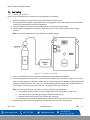
7.2 Calibration and Test Kits ................................................................................................................................. 28
7.3 Gas Testing ..................................................................................................................................................... 30
7.3.1 Testing the Fan Relay .............................................................................................................................. 30
7.3.2 Testing the Alarm Relay .......................................................................................................................... 31
7.3.3 Testing the 4-20mA loop ........................................................................................................................ 31
7.4 Field Calibration Procedure ............................................................................................................................ 32
7.4.1 Zero the Sensor....................................................................................................................................... 32
7.4.2 Calibration .............................................................................................................................................. 32
8 Appendix A – Table of Figures ................................................................................................................................ 33
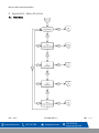
9 Appendix B – Menu Structure ................................................................................................................................ 34
9.1 Main Menu ..................................................................................................................................................... 34
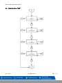
9.2 Auto Test Menu “bUZ” ................................................................................................................................... 35
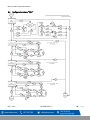
9.3 Configuration Menu “CON” ............................................................................................................................ 36
9.4 Select Test Menu “tst” .................................................................................................................................... 46
9.5 CAL Menu ....................................................................................................................................................... 47
9.6 Sensor Reset Menu “Sen” .............................................................................................................................. 48
10 Macurco Gas Detection Product limited warranty ............................................................................................. 49
Technical Support Contact Information ....................................................................... Error! Bookmark not defined.
General Contact Information ....................................................................................... Error! Bookmark not defined.

Macurco GD-xx Operation Manual
REV – 1.0.2 [34-2900-0027-6 ] 4 | Page
1 General Safety Information
1.1 List of warnings
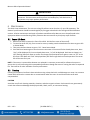
WARNING
Each person using this equipment must read and understand the information in this
user manual before use. Use of this equipment by untrained or unqualified persons or
use that is not in accordance with this user manual, may adversely affect product
performance.
Use only for monitoring the gas which the sensor and monitor is designed to detect.
Failure to do so may result in exposures to gases not detectable and cause serious
injury or death. For proper use, see supervisor or user manual, or contact Technical
Support at 1-844-325-3050.
This equipment may not function effectively below 0°F or above 125°F (-18°C or above
52°C). Using the detector outside of this temperature range may adversely affect
product performance.
This detector helps monitor for the presence and concentration level of a certain
specified airborne gas. Misuse may produce an inaccurate reading, which means that
higher levels of the gas being monitored may be present and could result in
overexposure and cause serious injury or death. For proper use, see supervisor or User
manual, or contact Technical Support at 1-844-325-3050.
High voltage terminals (120/240 VAC) are located within this detector, presenting a
hazard to service technicians. Only qualified technicians should open the detector case
and service the internal circuits. Ensure power is de-energized from the detector relays
prior to servicing the unit. Failure to do so may result in electrical shock.
Do not disassemble unit or attempt to repair or modify any component of this
instrument. This instrument contains no user serviceable parts, and substitution of
components may impair product performance.
Using a certified gas with a concentration other than the one listed for this detector
when conducting a calibration verification test (bump test) will produce inaccurate
readings. This means that higher levels of the gas being monitored may be present and
could result in overexposure. For proper use, see supervisor or User manual, or
contact Technical Support at 1-844-325-3050.
The following steps must be performed when conducting a calibration verification test
(bump test) to ensure proper performance of the monitor. Failure to do so may
adversely affect product performance.
• When performing a calibration verification test (bump test) only use certified
calibration gas at the required concentration level.
• Do not test with expired calibration gas.
• Do not cover or obstruct display or visual alarm cover.
• Ensure sensor inlets are unobstructed and are free of debris
Failure to follow instructions outlined in this user manual can result in sickness or
death.

Macurco GD-xx Operation Manual
REV – 1.0.2 [34-2900-0027-6 ] 5 | Page
2 Use Instructions and Limitations
The GD-6 is a low voltage, dual relay combustible gas detector and automatic ventilation controller. The GD-6 uses a
microcomputer controlled, electronic system to measure the concentration of combustible gas, actuate relays and
provide a 4-20 mA output. The GD-6 has a low maintenance long life (5+ years) pellistor sensor and optional gas test
and calibration kits. The GD-6 is a low-level meter capable of displaying from 0-50% LEL of combustible gas.
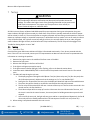
WARNING
Each person using this equipment must read and understand the information in this
user manual before use. Use of this equipment by untrained or unqualified persons or
use that is not in accordance with this user manual, may adversely affect product
performance.
NOTE: Combustible gas detectors will respond to a wide range of hydrocarbons, including aerosol sprays, cleaning
solvents, paint thinner and other common household items. Be alert to other hydrocarbons near the detector
before assuming that the unit is false alarming or is defective.
2.1 Use For
The GD-6 provides combustible gas detection and automatic exhaust fan, louver or valve control for automotive
maintenance facilities, enclosed parking garages, utility rooms, battery rooms, warehouses with forklifts and other
commercial applications. The GD-6 can be used stand alone, with the Macurco DVP-120 Detection and Ventilation
Control Panel, other 12 VAC or 24 VDC fire/security panels or building automation systems.
WARNING
Use only for monitoring the gas which the sensor and monitor is designed to detect.
Failure to do so may result in exposures to gases not detectable and cause serious
injury or death. For proper use, see supervisor or user manual, or contact Technical
Support at 1-844-325-3050.
2.2 Do NOT use for
The GD-6 is not intended for use in hazardous locations or industrial applications such as refineries, chemical plants,
etc. Do not mount the GD-6 where the normal ambient temperature is below 0°F or exceeds 125°F (-18°C or above
52°C). The GD-6 mounts on a type 4S electrical box supplied by the contractor. Do not install the GD-6 inside another
box unless it has good air flow through it.
WARNING
This equipment may not function effectively below 0°F or above 125°F (-18°C or above
52°C). Using the detector outside of this temperature range may adversely affect
product performance.

Macurco GD-xx Operation Manual
REV – 1.0.2 [34-2900-0027-6 ] 6 | Page
2.3 Features
• ETL Listed to UL 61010-1 and CAN/CSA C22.2 No 61010-1
• Low level meter capable of displaying from 0-50% LEL
• Selectable target gas – Methane (mE), Propane (Pro) or Hydrogen (Hy)
• Selectable fan and alarm relay activation
• 5 A SPDT fan relay controls starters of exhaust fans
• 0.5 A N.O. or N.C. alarm relay connects to warning devices or control panels
• 4-20 mA current loop
• GD-6 mounts on a standard 4x4 electrical box and becomes cover for the box
• Supervised system: any internal detector problem will cause the fan & alarm relay to activate
• Calibration kit is available. One screw allows access for calibration or gas test
2.4 Specifications
• Shipping Weight: 1 pound (0.45 kg)
• Size: 4 1/2 x 4 x 2 1/8 in. (11.4 X 11.4 X 5.3 cm)
• Color: Dark gray
• Connections: plugs/terminals
• Mounting box: (not included) 4x4 electric
• Fan relay: 5 A, 240 VAC, pilot duty, SPDT, latching or non-latching
• Fan relay actuation: selectable at diS (disable) 3, 4, 5, 6, 7, 8, 9, 10 (default), 11, 12, 13, 14, 15, 16, 17, 18, 19,
20% LEL
• Fan Delay Settings of 0, 1, 3 (default), 5 and 10 minutes
• Fan Minimum Run Time settings are 0 (default), 3, 5, 10 or 15 minutes
• Fan relay latching or not latching (default) selectable
• Alarm relay: 0.5A 120 V, 60 VA
• Alarm relay actuation: selectable N.O. default or N.C.
• Alarm relay settings: diS, 5, 10, 15, 20 (default), 25% LEL
• Current loop, 4-20 mA for 0-50% LEL, selectable to off or on (default)
• Buzzer: 85 dBA at 10cm settable to off (default) or on
• Digital display: 3-digit LED selectable to off (default) or on.
• Operating Environment: 0 ° F to 125 ° F (-18 ° C to 52 ° C). 10 to 90% RH noncondensing
2.4.1 6-Series Low Voltage
• Power: 3 W (max) from 12 to 24 VAC or 12 to 48 VDC
• Current @ 24VDC: 75 mA in alarm (two relays), 50 mA (fan relay only) and 23 mA stand by
2.4.2 12-Series Line Voltage
• Power: 100-240VAC (50 TO 60 HZ)
• Current: 1.0 A MAX

Macurco GD-xx Operation Manual
REV – 1.0.2 [34-2900-0027-6 ] 7 | Page
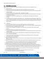
3 Installation and Operating Instructions
The following instructions are intended to serve as a guideline for the use of the Macurco GD-6 Combustible Gas
Detector. It is not to be considered all-inclusive, nor is it intended to replace the policy and procedures for each
facility. If you have any doubts about the applicability of the equipment to your situation, consult an industrial
hygienist or call Technical Service at 844-325-3050.
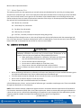
WARNING
This detector helps monitor for the presence and concentration level of a certain
specified airborne gas. Misuse may produce an inaccurate reading, which means that
higher levels of the gas being monitored may be present and could result in
overexposure and cause serious injury or death. For proper use, see supervisor or User
manual, or contact Technical Support at 1-844-325-3050.
3.1 Location
A GD-XX mounting height is dependent upon the target gas.
• If the target gas is lighter than air; methane (NG) or Hydrogen (H2), mount the GD-6 high on a wall or column
(about one foot down from the ceiling) in a central area where air movement is generally good. • If the target gas is
heavier than air; propane (LP), mount the GD-6 low on a wall or column (about one foot above the floor) in a central
area where air movement is generally good.
The unit, on average, can cover approximately 900 sq. ft. (84 sq. meters) to 1,257 sq. ft. (117 sq. meters). The
coverage depends on air movement within the room or facility. Extra detectors may be needed near any areas
where people work or where the air is stagnant. Some of the factors that affect the coverage area are application
type, personnel work areas and movement, room size, air movement, potential threat, mounting location, along
with other site-specific factors that must be considered. Please check local regulations or requirements prior to
installation. The GD-6 mounts on a 4x4 electrical box supplied by the contractor. Do not install the GD-6 inside
another box unless it has good air flow through it. Do NOT mount the GD-6 where the normal ambient temperature
is below 0°F or exceeds 125°F (below -18°C or above 52°C).
WARNING
High voltage terminals (120/240 VAC) are located within this detector, presenting a
hazard to service technicians. Only qualified technicians should open the detector case
and service the internal circuits. Ensure power is de-energized from the detector relays
prior to servicing the unit. Failure to do so may result in electrical shock.

Macurco GD-xx Operation Manual
REV – 1.0.2 [34-2900-0027-6 ] 8 | Page
3.2 Installation
3.2.1 6-Series Low Voltage
1. The GD-6 mounts on a 4” square (or 4x4) electrical box supplied by the contractor. Do not mount the GD-6
inside another box, unless it has good air flow through it.
2. Connect the GD-6 to Class 2 power supply only. It is suggested to use a separate transformer for powering
the unit or units because of possible interferences from other devices on the same power supply.
3. Connect the GD-6 to the control cables with terminal plugs. When making connections, make sure the
power is off.
4. There are two terminals for Power: 12 to 24 VAC or 12 to 48 VDC, with no polarity preference.
5. There are two terminals for the dry alarm relay contacts, again with no polarity preference. The alarm relay
can switch up to 0.5 A 120 V, or 60 VA. The alarm relay is activated if gas reaches or exceeds the alarm
settings. See OPERATION section of these User Instructions for details on relay settings.
6. The alarm relay can be configured to normally open (default) (N.O.) or normally closed (N.C.) and will
activate if the gas concentration exceeds alarm set point. It will deactivate once the gas concentration drops
below the alarm set point. Note that the “disable” setting will cause the alarm relay not to engage at all.
7. The dry contact, SPDT fan relay has three terminals. The common (COM.), normally open (N.O.) and the
normally closed (N.C.) contact. The fan relay can switch up to 5.0 A up to 240 VAC. See OPERATION section
of these User Instructions for details on relay settings.
8. The Fan Relay can be configured for latching or non-latching (default) when activated (when the gas
concentration exceeds fan relay set point). Once latched in, power will need to be interrupted or the “TEST”
button pressed to un-latch the relay condition.
9. The Fan Relay will engage if the fan setting Combustible Gas concentration is exceeded for longer than the
Fan Relay Delay time. Unless it is configured for latching, the fan relay will disengage once both of these
conditions have been met:
a. Combustible Gas concentration has dropped below fan setting
b. Fan Relay Run time has been exceeded
Note that the “disable” fan setting will cause the fan relay to not engage. The fan relay will engage in trouble
fault condition (if the Trouble Fan Setting Option is set to “ON”) and will disengage once trouble fault
condition is cleared.
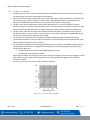
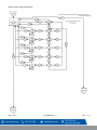
10. The Current Loop is 4 mA in clean air and 4-20 mA for 0-50% LEL

Macurco GD-xx Operation Manual
REV – 1.0.2 [34-2900-0027-6 ] 9 | Page
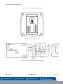
Figure 3-1 – 6-Sereis 4-20 mA Output diagram
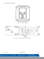
Figure 3-2 – 6-Series Rear View
Figure 3-3 – 6-Series typical Standalone Installation

Macurco GD-xx Operation Manual
REV – 1.0.2 [34-2900-0027-6 ] 10 | Page
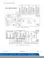
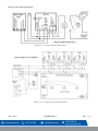
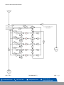
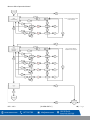
Figure 3-4 – 6-Series Multiple Device
Figure 3-5 – 6-Series Alarm Control Panel

Macurco GD-xx Operation Manual
REV – 1.0.2 [34-2900-0027-6 ] 11 | Page
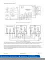
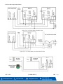
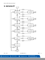
Figure 3-6 – 6-Series DVP-120 Control Panel
Figure 3-7 – 6-Series Alternate Alarm Panel
In this application (above) the Fan or primary relay is used as a low-level alarm relay. The Alarm or secondary relay is
used as a supervisory relay when utilized in the normally closed configuration. The GD-6 monitors all critical
functions of the unit through software diagnostics that continually test and verify its operations. If a problem is
found, the unit will switch to a fail-safe/error mode or trouble condition. In this error mode the Fan* and Alarm
relays will be activated indicating the trouble condition at panel and the GD-6 display will flash the error. *See the
Trouble Fan Setting Option.

Macurco GD-xx Operation Manual
REV – 1.0.2 [34-2900-0027-6 ] 12 | Page
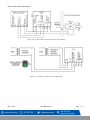
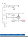
Figure 3-8 – 6-Series Alarm Panel and Shutoff Valve Wiring
Figure 3-9 – 6-Series Horn & Strobe Combo Wiring

Macurco GD-xx Operation Manual
REV – 1.0.2 [34-2900-0027-6 ] 13 | Page
3.2.2 12-Series Line Voltage
1. The GD-12 mounts on a 4” square (or 4x4) electrical box supplied by the contractor. Do not mount the GD-
12 inside another box, unless it has good air flow through it.
2. There are two terminals for the dry alarm relay contacts, again with no polarity preference. The alarm relay
can switch up to 0.5 A 120 V, or 60 VA. The alarm relay is activated if gas reaches or exceeds the alarm
settings. See OPERATION section of these User Instructions for details on relay settings.
3. The alarm relay can be configured to normally open (default) (N.O.) or normally closed (N.C.) and will
activate if the gas concentration exceeds alarm set point. It will deactivate once the gas concentration drops
below the alarm set point. Note that the “disable” setting will cause the alarm relay not to engage at all.
4. The dry contact, SPDT fan relay has three terminals. The common (COM.), normally open (N.O.) and the
normally closed (N.C.) contact. The fan relay can switch up to 5.0 A up to 240 VAC. See OPERATION section
of these User Instructions for details on relay settings.
5. The Fan Relay can be configured for latching or non-latching (default) when activated (when the gas
concentration exceeds fan relay set point). Once latched in, power will need to be interrupted or the “TEST”
button pressed to un-latch the relay condition.
6. The Fan Relay will engage if the fan setting Combustible Gas concentration is exceeded for longer than the
Fan Relay Delay time. Unless it is configured for latching, the fan relay will disengage once both of these
conditions have been met:
• Combustible Gas concentration has dropped below fan setting
• Fan Relay Run time has been exceeded
Note that the “disable” fan setting will cause the fan relay to not engage. The fan relay will engage in trouble
fault condition (if the Trouble Fan Setting Option is set to “ON”) and will disengage once trouble fault
condition is cleared.
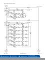
7. The Current Loop is 4 mA in clean air and 4-20 mA for 0-50% LEL
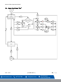
Figure 3-9 – 12-Series 4-20 mA Output

Macurco GD-xx Operation Manual
REV – 1.0.2 [34-2900-0027-6 ] 14 | Page
Figure 3-10 – 12-Series Rear View
Figure 3-11 – 12-Series Typical Standalone Installation

Macurco GD-xx Operation Manual
REV – 1.0.2 [34-2900-0027-6 ] 15 | Page
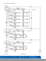
Figure 3-12 – 12-Series Use with Alarm Panel
Figure 3-13 – 12-Series DVP-120 Control Panel

Macurco GD-xx Operation Manual
REV – 1.0.2 [34-2900-0027-6 ] 16 | Page
Figure 3-14 – 12-Series Alternate Alarm Panel
Figure 3-15 – 12 Series Alarm Panel with Shutoff Valve

Macurco GD-xx Operation Manual
REV – 1.0.2 [34-2900-0027-6 ] 17 | Page
Figure 3-15 – 12-Series Horn & Strobe Combo Wiring
3.3 Terminal Connection
3.3.1 6-Series Low Voltage
With the exception of the safety ground, all field wiring is completed via modular connectors (provided). After wiring, simply
plug the modular connectors into the matching connectors on the back side of the detector.
NOTE: 22 to 12 AWG wire shall be used. Wire used shall meet the temperature range of the detector i.e. 0°F to 125°
F (-18°C to 52°C).
3.3.1.1 Mains Power Connection
Connect the GD-6 to Class 2 power supply only. It is suggested to use a separate transformer for powering the unit or units
because of possible interferences from other devices on the same power supply. Connect the GD-6 to the control cables with
terminal plugs. When making connections, make sure the power is off. There are two terminals for Power: 12 to 24 VAC or 12 to
32 VDC, with no polarity preference
Ensure that the wire cannot be easily pulled from the connector. Plug the modular connection into the Fan/Power connection
and ensure that it latches into the header properly.
3.3.1.2 Fan Relay Connection
All of the SPDT Fan relay terminals are available at the Fan/Power modular connector. Each Fan relay terminal normally open,
common and normally closed (NO, COM and NC) can accommodate a wire size 12 to 22 AWG. To install the wiring for the relays,
disconnect the connector from the header. Strip the insulation of each wire back approximately 1/4 in. (6.5 mm), insert the bare
wire into the terminal and tighten the screw clamp. Ensure that the wire cannot easily be pulled from the connector. Plug the
modular connection into the Fan/Power connection and ensure that it latches into the header properly.
3.3.1.3 Alarm Relay Connection
The external alarm connections (A and B) are available at the Alarm modular connector. There is no polarity for these
connections. To install the wiring for the alarm contacts, disconnect the connector from the header on the detector. Strip the
insulation of each wire back approximately 1/4 in. (6.5 mm), insert the bare wire into the terminal and tighten the screw clamp.
Ensure that the wire cannot easily be pulled from the connector. When the wires are connected seat the modular connector
into the header ensuring that the latch engages
3.3.1.4 4-20 mA Signal Connection
The positive and negative 4-20mA signal connections (+ and -) are available at the 4-20mA modular connector, a 2-
position connector. To install the wiring for the 4-20 mA contacts, disconnect the connector from the header on the
detector. Strip the insulation of each wire back approximately 1/4 in. (6.5 mm), insert the bare wire into the terminal
and tighten the screw clamp. Ensure that the wire cannot easily be pulled from the connector. When the wires are
connected seat the modular connector into the header ensuring that the latch engages
3.3.2 12-Series Line Voltage
With the exception of the safety ground, all field wiring is completed via modular connectors (provided). After
wiring, simply plug the modular connectors into the matching connectors on the back side of the detector.

Macurco GD-xx Operation Manual
REV – 1.0.2 [34-2900-0027-6 ] 18 | Page
3.3.2.1 Power Connection
Mains connections should be done in accordance with National and Local Electrical Codes. Only qualified personnel
should connect Mains power to any device. Macurco recommends a minimum wire size of AWG18 and the wire
insulator must be rated for 140°F (60°C) service. The modular connector will accept wire from 12 to 24 AWG.
The safety ground wire should be secured to the ground screw of the metal electrical box. Tighten the screw and
make sure the wire is snug. Ensure that the wire cannot be pulled out from under the screw.
The Line (L) and Neutral (N) wires should be stripped 1/4 in. (6.5 mm), insert the wire into the ”L” and “N” wire
positions of the modular Fan/Power connector and tighten the screw clamp. Ensure that the wire cannot be easily
pulled from the connector. Plug the modular connection into the Fan/Power connection and ensure that it latches
into the header properly.
3.3.2.2 Fan Relay connection
All of the SPDT Fan relay terminals are available at the Fan/Power modular connector. Each Fan relay terminal
normally open, common and normally closed (NO, COM and NC) can accommodate a wire size 12 to 24 AWG. To
install the wiring for the relays, disconnect the connector from the header. Strip the insulation of each wire back
approximately 1/4 in. (6.5 mm), insert the bare wire into the terminal and tighten the screw clamp. Ensure that the
wire cannot easily be pulled from the connector. Plug the modular connection into the Fan/Power connection and
ensure that it latches into the header properly.
3.3.2.3 Alarm Relay Connection
The external alarm connections (A and B) are available at the Alarm modular connector. There is no polarity for
these connections. To install the wiring for the alarm contacts, disconnect the connector from the header on the
detector. Strip the insulation of each wire back approximately 1/4 in. (6.5 mm), insert the bare wire into the terminal
and tighten the screw clamp. Ensure that the wire cannot easily be pulled from the connector. When the wires are
connected seat the modular connector into the header ensuring that the latch engages.
3.3.2.4 4-20 mA Signal connection
The positive and negative 4-20mA signal connections (+ and -) are available at the 4-20mA modular connector, a 2-
position connector. To install the wiring for the 4-20 mA contacts, disconnect the connector from the header on the
detector. Strip the insulation of each wire back approximately 1/4 in. (6.5 mm), insert the bare wire into the terminal
and tighten the screw clamp. Ensure that the wire cannot easily be pulled from the connector. When the wires are
connected seat the modular connector into the header ensuring that the latch engages.
NOTE: The 4-20mA current loop outputs may be used with the Macurco DVP-120 control panel or other systems.
The 4-20mA signal connections to detectors should be size AWG18 (minimum) for short runs. Refer to the table for
recommended wire gauges. Do not bundle detector 4-20mA signal connections with AC power cables to prevent
electrical interference. If AC power connections must be bundled with the detector 4-20mA signal cables, the signal
connections should be made with twisted pair of the appropriate gauge, with an overall foil and braid shield. All
shields should be terminated at the DVP-120 end of the cable only. A ground stud is provided near the bottom left
corner of the DVP-120 panel.

Macurco GD-xx Operation Manual
REV – 1.0.2 [34-2900-0027-6 ] 19 | Page
4 Operations
4.1 Power up
The GD-6 cycles through an internal self-test cycle for the first minute that it is powered. The unit will execute the
test cycle any time power is dropped and reapplied (i.e. power failure). During the self-test cycle, the unit will
display the firmware version number, then count down from 60 to 0 (if the display setting is “On”) and finally go into
normal operation. The alarm relay will be activated for 10 seconds and the fan relay for 60 seconds during the
power-up cycle unless the “Power Up Test” (PUt) option is OFF. The indicator light (LED) will flash green during the
self-test cycle. At the end of the 1-minute cycle, the unit will take its first sample of the air and the indicator light will
turn solid green.
4.2 Display turned “On”
Clean Air – With the display function turned “On”, the GD-xx will show the current concentration of combustible gas
in % LEL or “0.0” (zero) in clean air.
Fan level – When the gas concentration reaches the Fan Relay setting (10.0, for example) the display will flash back
and forth between “FAn” and “10.0” or current concentration of gas.
Alarm level – With the display function turned “On” and the gas concentration reaching the Alarm Relay setting,
(20.0 %, for example) the display will flash back and forth between “ALr” and “20.0” or current concentration of gas.
The buzzer will sound indicating “Alarm” if the buzzer is turned “On”.
Trouble – With the display function turned “On” and the device is in a trouble state, the display will display the “t”
Error code (t01 for example). If the Trouble Fan Setting is enabled, the Fan relay will switch activating the relay. See
section 4.5.11 Trouble Fan Setting – “tFS” and section 5.1.2 “t” Error Codes and
Calibration Due- With Calibration Period functionality enabled, if a detector is within 1 month of calibration period,
then display will flash back and forth between “dUE” and current gas reading. Calibration Due is resolved only with
successful field calibration.
4.3 Display turned “Off”
Clean Air – With the display function turned ”Off”, the display does not show the gas concentration. Only the Power
indicator light on will be on.
Fan Level – When the gas concentration reaches the Fan Relay setting (10.0, for example) the display will show
“FAn” continuously as long as the fan relay is enabled. This appears as slowly flashing “FAn”.
Alarm Level – With the display function turned off the display does not show the gas concentration but will show
“ALr” when the Alarm relay is activated.
Trouble – With the display function turned “Off” and the device is in a trouble state, the display will display the “t”
Error code (t01 for example). If the Trouble Fan Setting is enabled, the Fan relay will switch activating the relay. See
Section 4.5.11 Trouble Fan Setting – “tFS” and Section 5.1.2 “t” Error Codes.
Calibration Due- With Calibration Period functionality enabled, if a detector is within 1 month of calibration period,
then display will show “dUE” continuously. Calibration Due is resolved only with successful field calibration.

Macurco GD-xx Operation Manual
REV – 1.0.2 [34-2900-0027-6 ] 20 | Page
4.4 4-20mA Loop
4-20mA settings selected to ‘bAS’ or ‘EnH’ is considered as 4-20mA function turned ON.
Clean Air – With the 4-20 mA function turned “On” and the current concentration of gas at “0.0” (zero), the 4-20mA
loop will output 4 mA.
Gas read – With the 4-20 mA function turned “On” the output will read between 4 mA and 20 mA depending on the
current concentration of methane, propane or hydrogen.
Trouble – With the 4-20 mA function turned “On” and Trouble Fan Setting enabled. The 4-20mA loop will output 1
mA or 24 mA depending on the Trouble condition. See Section 5.1 On-Board Diagnostics.
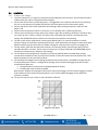
4.5 Default – Factory Settings
Setting:
Default:
Gas
mE (methane)
Power Up Test
On
Display
Off
Buzzer
Off
Alarm Relay Setting
20% LEL
Alarm Relay Configuration
Normally Open (NO)
Fan Relay Setting
10% LEL
Fan Relay Delay
3 minutes
Fan Relay Minimum Runtime
0 minutes
Fan Relay Latching
Off
Trouble Fan Setting
Off
4-20mA
On
Table 4-1 – Default settings
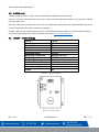
Figure 4-1 – Board View
Page is loading ...
Page is loading ...
Page is loading ...
Page is loading ...
Page is loading ...
Page is loading ...
Page is loading ...
Page is loading ...
Page is loading ...
Page is loading ...
Page is loading ...
Page is loading ...
Page is loading ...
Page is loading ...
Page is loading ...
Page is loading ...
Page is loading ...
Page is loading ...
Page is loading ...
Page is loading ...
Page is loading ...
Page is loading ...
Page is loading ...
Page is loading ...
Page is loading ...
-
 1
1
-
 2
2
-
 3
3
-
 4
4
-
 5
5
-
 6
6
-
 7
7
-
 8
8
-
 9
9
-
 10
10
-
 11
11
-
 12
12
-
 13
13
-
 14
14
-
 15
15
-
 16
16
-
 17
17
-
 18
18
-
 19
19
-
 20
20
-
 21
21
-
 22
22
-
 23
23
-
 24
24
-
 25
25
-
 26
26
-
 27
27
-
 28
28
-
 29
29
-
 30
30
-
 31
31
-
 32
32
-
 33
33
-
 34
34
-
 35
35
-
 36
36
-
 37
37
-
 38
38
-
 39
39
-
 40
40
-
 41
41
-
 42
42
-
 43
43
-
 44
44
-
 45
45


Ask a question and I''ll find the answer in the document
Finding information in a document is now easier with AI
Related papers


Other documents
-
3M MACURCO GD-6 User manual
-
-
APC UTS6H Specification
-
Genesis SHERLOCK 202 Operating instructions
-
SMC M2400 Owner's manual
-
General Monitors TA102A Owner's manual
-
-
-
Crowcon VORTEX User manual
-