Page is loading ...

www.ismacontrolli.com
DMP258en | 1st Issue rev. 5 | 11/2023
iSMA-B-MAC36NL
iSMA-B-MAC36PRO
User Manual
Local I/O

MAC36 Controllers LocalIO User Manual
www.ismacontrolli.com
DMP258en | 1st Issue rev. 5 | 11/2023
page 2 of 32
Table of Contents
1 Introduction ..................................................................................................................................3
1.1 Revision History.................................................................................................................................... 3
2 LocalIO Hardware Specification...............................................................................................4
3 Terminals and Internal Connection Diagram .......................................................................5
4 LED Indicators ..............................................................................................................................6
5 Universal Inputs ...........................................................................................................................7
5.1 Voltage Input Connection (0-10 V DC)............................................................................................ 7
5.2 Current Input Connection (0-20 mA).............................................................................................. 7
5.3 Temperature Input Connection ....................................................................................................... 8
5.4 Dry Contact Input Connection (Digital Input)................................................................................ 8
6 Digital Inputs.............................................................................................................................. 10
7 Analog Outputs ......................................................................................................................... 11
7.1 Voltage Output Connection (0-10 V DC) ......................................................................................11
7.2 Relay to Analog Output Connection ............................................................................................. 11
8 Digital Outputs .......................................................................................................................... 12
8.1 Resistive Load Connection ..............................................................................................................12
8.2 Solenoid Valve Connection ............................................................................................................. 12
9 LocalIO Driver............................................................................................................................ 13
9.1 iSMAIONetwork..................................................................................................................................13
9.2 LocalIODevice..................................................................................................................................... 14
9.3 UniversalInput ....................................................................................................................................15
9.4 DigitalUniversalInput.........................................................................................................................18
9.5 DigitalInput..........................................................................................................................................20
9.6 DigitalInputCounter........................................................................................................................... 21
9.7 AnalogOutput .....................................................................................................................................23
9.8 DigitalOutput ......................................................................................................................................26
9.9 RotarySwitch .......................................................................................................................................29
9.10 DIPSwitch.............................................................................................................................................30

MAC36 Controllers LocalIO User Manual
www.ismacontrolli.com
DMP258en | 1st Issue rev. 5 | 11/2023
page 3 of 32
•
•
•
•
•
•
•
1 Introduction
MAC36 are compact Master Application Controllers powered by the Niagara Framework,
with various types of 36 onboard inputs and outputs. Using the specific local I/O set of 16
UI, 8 AO, 4 DI, and 8 DO allows to employ the devices in different applications. MAC36
controllers provide control, data logging, alarming, scheduling, integration, and
visualization.
The range of MAC36 controllers consists of:
iSMA-B-MAC36NL;
iSMA-B-MAC36PRO.
1.1 Revision History
Rev. Date Description
1.5 10 Nov 2023 MAC36PRO references
1.4 25 May 2022 Rebranded
DigitalUniversalInput component description added
Polarity conversion functionality added to DigitalInput and
DigitalOutput components
1.3 16 Dec 2020 Document corrections
1.2 31 Mar 2020 Rotary and DIP switches support added
1.1 31 Oct 2019 New temperature sensors supported
New features: universal input resistance offset, linear
conversion, custom table, analog output linear conversion
1.0 1 Oct 2018 First edition
Table 1. Revision history

MAC36 Controllers LocalIO User Manual
www.ismacontrolli.com
DMP258en | 1st Issue rev. 5 | 11/2023
page 4 of 32
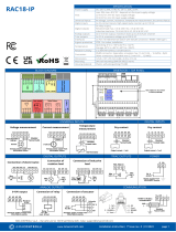
2 LocalIO Hardware Specification
MAC36 controllers have various types of 36 onboard inputs and outputs. Using the
specific local I/O set of 16 UI, 8 AO, 4 DI, and 8 DO allows to employ the devices in
different applications.
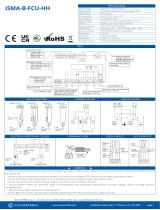
Figure 1. MAC36NL controller
Figure 2. MAC36PRO controller

MAC36 Controllers LocalIO User Manual
www.ismacontrolli.com
DMP258en | 1st Issue rev. 5 | 11/2023
page 5 of 32
•
•
•
•
3 Terminals and Internal Connection Diagram
MAC36 controllers are supplied by 24 V AC/DC. The power supply block is separated. The
grounding pin, located next to power supply terminals, must be connected to the ground.
The device has 36local I/O on board:
8 digital outputs (8 DO), relay output with max. load 3 A at 230 V AC/30 V DC;
8 analog outputs (8 AO), voltage output 0-10 V DC maximum load up to 20 mA;
16 universal inputs (16 UI), temperature, voltage, current, resistive,or dry contact;
4 digital inputs (4 DI), dry contact inputs or fast counter up to 100 Hz.
Figure 3. Block diagram

MAC36 Controllers LocalIO User Manual
www.ismacontrolli.com
DMP258en | 1st Issue rev. 5 | 11/2023
page 6 of 32
•
•
•
•
4 LED Indicators
The device is equipped with LEDs for quick status checking and diagnostics:
Figure 4. LEDs of a front panel of the iSMA-B-MAC36NL-RS
Figure 5. LEDs of a front panel of the iSMA-B-MAC36PRO-RS
The universal inputs LEDs U1-U16 indicate the statuses of the universal inputs. If the
LED is ON, the resistance value connected to the input is lower than the switching
threshold value (dry contact input is active).
Note: The LED also lights up if the voltage connected to the input has a very low potential.
The digital inputs LEDs I1-I4 indicate the statuses of the digital inputs. If the LED is ON,
the input is active (resistance value connected to the input is lower than the switching
threshold value).
The analog outputs LEDs A1-A8 indicate the statuses of the analog outputs. If the LED
is ON, the output voltage or PWM factor is different than 0.
The digital outputs LEDs O1-O8 indicate the statuses of the digital outputs. If the LED
is ON, the output is active (closed circuit).

MAC36 Controllers LocalIO User Manual
www.ismacontrolli.com
DMP258en | 1st Issue rev. 5 | 11/2023
page 7 of 32
•
•
•
•
•
5 Universal Inputs
All universal inputs have 16-bit ADC, which supports the following types of input signals:
voltage input (0-10 V DC);
current input (0-20 mA);
resistive input (0-1000 kΩ);
temperature input;
dry contact input (digital input).
5.1 Voltage Input Connection (0-10 V DC)
Figure 6. Universal input voltage connection
5.2 Current Input Connection (0-20 mA)
The current measurement is realized by a voltage measurement and a 200 Ω resistance.
According to Ohm’s law, the current is directly proportional to the voltage, and the
resistance is the constant of proportionality (I = U / R).
According to the Ohm’s law equation, for 20 mA current with 200 Ω resistance the output
voltage is 4 V.
It means that the 4 V voltage measured on the universal input corresponds to 20 mA
current.
The result is expressed in millivolts.

MAC36 Controllers LocalIO User Manual
www.ismacontrolli.com
DMP258en | 1st Issue rev. 5 | 11/2023
page 8 of 32
Figure 7. Universal input voltage connection
5.3 Temperature Input Connection
The temperature measurement is based on a resistance.
The universal inputs, working as temperature inputs, support the following types of
sensors: series NTC 10K3A1, 10K4A1, Carel 10K, 20K6A1, 2.2K3A1, 3K3A1, 30K6A1, SIE1,
TAC1, SAT1, and PT1000, NI1000.
Figure 8. Universal input voltage connection
5.4 Dry Contact Input Connection (Digital Input)
The universal inputs can operate as standard digital inputs (dry contact inputs).
The input is active if it is connected to the ground (G0).

MAC36 Controllers LocalIO User Manual
www.ismacontrolli.com
DMP258en | 1st Issue rev. 5 | 11/2023
page 9 of 32
Figure 9. Universal input voltage connection

MAC36 Controllers LocalIO User Manual
www.ismacontrolli.com
DMP258en | 1st Issue rev. 5 | 11/2023
page 10 of 32
6 Digital Inputs
In addition to a standard dry contact input, digital inputs can operate as fast pulse
counters with up to 100 Hz pulse frequency counting.
The input is active if it is connected to the ground (G0).
Figure 10. Digital input in dry contact mode

MAC36 Controllers LocalIO User Manual
www.ismacontrolli.com
DMP258en | 1st Issue rev. 5 | 11/2023
page 11 of 32
•
•
7 Analog Outputs
All analog outputs have 12-bit ADC, provide 10 mV resolution, and accuracy less than
±0,5%. They support the following types of output signals:
voltage output (0-10 V DC) with max. load up to 20 mA;
PWM: 0,01 Hz, 0,1 Hz, 1 Hz, 10 Hz, 100 Hz.
7.1 Voltage Output Connection (0-10 V DC)
Figure 11. Analog output voltage connection
7.2 Relay to Analog Output Connection
There is an option to control the 12 V DC relay from the analog outputs (max. load cannot
exceed 20 mA!).
Figure 12. The analog output relay connection

MAC36 Controllers LocalIO User Manual
www.ismacontrolli.com
DMP258en | 1st Issue rev. 5 | 11/2023
page 12 of 32
8 Digital Outputs
Relay outputs (NO) have max. resistive load up to 3 A @ 230 V AC and 3 A @ 30 V DC.
8.1 Resistive Load Connection
Figure 13. The digital output connection of a resistive load
8.2 Solenoid Valve Connection
Figure 14. The digital output connection of a solenoid valve

MAC36 Controllers LocalIO User Manual
www.ismacontrolli.com
DMP258en | 1st Issue rev. 5 | 11/2023
page 13 of 32
•
•
•
•
•
•
•
•
•
•
•
•
•
9 LocalIO Driver
The LocalIO driver is dedicated to service, program, and maintain local I/Os.
The driver and local I/O points added under the iSMAIONetwork do not need a license–
they are free of charge and do not consume any points from the license.
The driver contains the following components:
iSMAIONetwork
LocalIODevice
UniversalInput
DigitalUniversalInput
DigitalInput
DigitalInputCounter
AnalogOutput
DigitalOutput
RotarySwitch
DIPSwitch
9.1 iSMAIONetwork
The iSMAIONetwork component is a network component for the local I/O device such as
MAC36 controllers (added using the LocalIODevice component). The iSMAIONetwork
component is the only right parent component for LocalIODevice components. MAC36
devices with points inside the iSMAIONetwork do not consume any of the license points.
Figure 15. The iSMAIONetwork component
The iSMAIONetwork component has the following slots:
Status: defines a current status of the component;
Ok: the component is working properly;
Disabled: the component has its communication disabled–the Enabled slot is set
to false;
Fault: indicates an incorrect configuration of the component;
Fault Cause: describes a cause of an error if there is a fault or down status;
None: no fault;
Bad Parent: the iSMAIONetwork component has been placed under a wrong
parent component (Drivers only);
Duplicated Component: the iSMAIONetwork component has been added twice;
Invalid Hardware: the iSMAIONetwork has been used on a device other than the
iSMA-B-MAC36NL or iSMA-B-MAC36PRO device;
Enabled: enables/disables the iSMAIONetwork component.

MAC36 Controllers LocalIO User Manual
www.ismacontrolli.com
DMP258en | 1st Issue rev. 5 | 11/2023
page 14 of 32
•
•
•
•
•
•
•
•
•
Figure 16. iSMAIONetwork in the Property Sheet
9.2 LocalIODevice
The LocalIODevice is a component that represents local I/Os of the iSMA-B-MAC36NL and
iSMA-B-MAC36PRO devices.
Figure 17. The LocalIODevice component
The component must be placed under the iSMAIONetwork component.
All local I/O points, which belong to a particular iSMA-B-MAC36NL or iSMA-B-MAC36PRO
device, must be placed under the LocalIODevice.
The LocalIODevice component has the following slots:
Status: defines a current status of the component, available states:
Ok: the component is working properly;
Disabled: the component or his parent (iSMA IO Network) is disabled (the
Enabled slot is false);
Fault: indicates an incorrect configuration of the component;
Fault Cause: describes a cause of an error if there is a fault or down status;
None: no fault;
Bad Parent: the component has been inserted in a wrong place in the structure
(the only correct place is the Device component or a subfolder of the Device
component);
Duplicated Component: appears if a component with the given address already
exists (prevents double representation of the input/output within an application);
Enabled: enables/disables the component;
Fast Rate: the time interval that specifies the target poll interval for components
assigned to this rate group;
Normal Rate: the time interval that specifies the target polling interval for the
components that can be polled and are assigned to a normal polling rate;
Slow Rate: the time interval that specifies the target polling interval for components
that can be polled and are assigned to a slow polling rate.
Slots hidden by default:
Write On Start: perform a writing action in the device’s writable components in the
iSMA IO Network after a reset or power-up;
Write On Up: perform a writing action in the device’s writable components in the iSMA
IO Network after restoring a connection with the device;
Write On Enable: perform a writing action in the device’s writable components in the
iSMA IO Network after enabling the device.

MAC36 Controllers LocalIO User Manual
www.ismacontrolli.com
DMP258en | 1st Issue rev. 5 | 11/2023
page 15 of 32
•
•
Figure 18. The LocalIODevice in the Property Sheet
9.3 UniversalInput
The UniversalInput component is a numeric point used for supporting physical local
universal inputs.
Figure 19. The UniversalInput component
The component must be placed under the LocalIODevice component.
The component can be configured to work in all modes of the universal input (resistance,
temperature, voltage, current, and digital).
Figure 20. The UniversalInput in the Property Sheet
The UniversalInput component has the following slots:
Facets: determines how an input value is displayed on available views in the station
with its unit and decimal point accuracy. By default, a value of the Facets slot depends
on a type of the input selected in the ProxyExt/Input Type slots. If the resistive input
type is set, the Facets slot will be set to Ohm and a number of decimal places to 0;
Proxy Ext: the component’s extension that handles the point's configuration and has
the following slots:
Status: indicates a current status of the component;
Ok: the component is working properly;

MAC36 Controllers LocalIO User Manual
www.ismacontrolli.com
DMP258en | 1st Issue rev. 5 | 11/2023
page 16 of 32
Disabled: the component or its parent (device or network) is disabled (the
Enabled slot is set to false);
Fault: indicates an incorrect configuration of the component;
Down: no response from the point;
Fault Cause: describes a cause of an error if there is a fault or down status;
None: no fault;
Bad Parent: the component has been inserted in a wrong place in the
structure (the only correct place is the Device component or a subfolder of
the Device component);
Duplicated Component: appears if a component with the given address
already exists (prevents double representation of the input/output within
an application);
Invalid Type: a type of component is not supported by the device;
Parent Disabled: a parent component (device or network) is disabled;
Point Down: the point is unavailable.
Enabled: enables/disables the component;
Poll Frequency: allows to select a poll frequency of the points, the available
options are: fast, normal, slow;
Input Number: allows to select an input number; if a point is added to the device,
the component selects the first unused input number automatically;
Max Input Number: shows the number of inputs available in the device;
Input Type: allows to select the input type (voltage, current, digital, resistive,
temperature).
•
•
•
•
Supported Input Types
The following input types are available:
Voltage: a universal input works as a voltage input: 0-10 V DC. The resistance
measurement is disabled;
Current: a universal input works as a current input: 0-20 mA. The resistance
measurement is disabled;
Digital: a universal input works like a digital input (dry contact input–output current
~1 mA). The voltage measurement is disabled;
Resistance: a universal input works in a resistive measurement mode (0 - 1000 kΩ).
The voltage measurement is disabled;

MAC36 Controllers LocalIO User Manual
www.ismacontrolli.com
DMP258en | 1st Issue rev. 5 | 11/2023
page 17 of 32
•
•
•
Resolution: allows to select resolution bits (16-bit resolution is recommended for
PT1000 and NI100 sensors);
Filter Time: allows to set the filter time 0-60 s;
Resistance Offset: allows to set the resistance offset value;
•Reading one of the supported types of temperature sensors (the voltage
measurement is disabled):
Temperature sensor type NTC 10K3A1 (ºC)
Temperature sensor type NTC 10K4A1 (ºC)
Temperature sensor type NTC 10K Carel (ºC)
Temperature sensor type NTC 20K6A1 (ºC)
Temperature sensor type NTC 2,2K3A1 (ºC)
Temperature sensor type NTC 3K3A1 (ºC)
Temperature sensor type NTC 30K6A1 (ºC)
Temperature sensor type SIE1 (ºC)
Temperature sensor type TAC1 (ºC)
Temperature sensor type SAT1 (ºC)
Temperature sensor type PT1000 (16-bit resolution pre-set by the manufacturer) (ºC)
Temperature sensor type NI1000 (16-bit resolution pre-set by the manufacturer) (ºC)
Temperature sensor type NI1000 LG (ºC)
Temperature sensor type NI1000 21C (ºC)
Temperature sensor type NTC 10K Type 2 (ºF)
Temperature sensor type NTC 10K Type 3 (ºF)
Temperature sensor type NTC 20K (ºF)
Temperature sensor type NTC 3K (ºF)
Temperature sensor type PT1000 (ºF)
Temperature sensor type NI1000 32F (ºF)
Temperature sensor type NI1000 70F (ºF)
Custom Table: users can enter their own sensor characteristics using up to 32 points
of characteristics.
After selecting a drop-down list from the Custom Table, an additional Custom Table
slot is displayed. This slot has the Resistance and Out value subslots for the next
points of the characteristics. If both subslots are filled in and approved with the Enter
key, the next subslots open in the next row. It is possible to enter up to 32 points of
characteristics (32 rows of Point 0...31). The characteristics are saved in the
component in the station. If the user changes the input mode, the characteristic will
be saved and it can be accessed by selecting the Custom Table again. To delete the
entered characteristic, right-click on the Custom Table slot and select Delete. The
UniversalInput component, with a saved characteristic, can be copied and used
repeatedly without having to re-enter it. The UniversalInput component can also be
copied between stations, both online and offline (PC copy). The Custom Table slot can
also be copied itself and pasted into a new UniversalInput component under the
ProxyExt (where there is no Custom Table yet). There can only be one Custom Table
slot in the UniversalInput component.

MAC36 Controllers LocalIO User Manual
www.ismacontrolli.com
DMP258en | 1st Issue rev. 5 | 11/2023
page 18 of 32
•
•
•
•
•
Linear Conversion: calculates a conversion of the input value according to the formula:
y=ax+b, where x = read input value; a = slot scale; b = slot offset;
Polarity Conversion: allows for the input to operate in a reversed polarity. The following
options are available from a drop-down list:
Direct:real-time value from a physical input is directly transferred to the Out slot
(default);
Reverse: real-time value from a physical input is reversed (1 to 0, 0 to 1), and
then transferred to the Out slot.
WARNING!
The Polarity Conversion slot works only if the UniversalInput component is set to
work in a digital input type.
Note: Please be cautious when using a reversed polarity, as this can lead to later
confusion when solving logic issues.
Out:provides a real-time information about the current value of the input
data,according to parameters set in the Facets slot, Polarity Conversion slot, and
current state of the point. If the input works correctly, the status is considered normal,
and the value is displayed with the default status {ok}.
The ProxyExt extension has the following actions:
Force Write Config: instantly saves point configurations to the physical device;
Force Read: sends a query immediately, despite the settings in the Poll Frequency slot.
Any change of the Input Number, Input Type, Resolution, or Filter Time slots results in
sending this configuration to the device immediately.
9.4 DigitalUniversalInput
The DigitalUniversalInput component is a Boolean point used for supporting physical
local universal inputs working as digital inputs.
Figure 21. The DigitalUniversalInput component
The component must be placed under the LocalIODevice component.
The componentcan work parallel with the UniversalInput point or on its own, and it does
not consume any additional license points.

MAC36 Controllers LocalIO User Manual
www.ismacontrolli.com
DMP258en | 1st Issue rev. 5 | 11/2023
page 19 of 32
•
•
Figure 22. The UniversalInput in the Property Sheet
The DigitalUniversalInput component has the following slots:
Facets: determines how an input value is displayed on the available views in the
station:
trueText: allows to set a text displayed for a true value;
falseText:allows to set a text displayed for a false value;
Proxy Ext: the component’s extension that handles the point's configuration and has
the following slots:
Status: indicates a current status of the component;
Ok: the component is working properly;
Disabled: the component or its parent (device or network) is disabled (the
Enabled slot is set to false);
Fault: indicates an incorrect configuration of the component;
Down: no response from the point;
Fault Cause: describes a cause of an error if there is a fault or down status;
None: no fault;
Bad Parent: the component has been inserted in a wrong place in the
structure (the only correct place is the Device component or a subfolder of
the Device component);
Duplicated Component: appears if a component with the given address
already exists (prevents double representation of the input/output within
an application);
Invalid Type: a type of component is not supported by the device;
Parent Disabled: a parent component (device or network) is disabled;
Point Down: the point is unavailable.
Enabled: enables/disables the component;
Poll Frequency: allows to select a poll frequency of the points, the available
options are: fast, normal, slow;
Input Number: allows to select an input number; if a point is added to the device,
the component selects the first unused input number automatically;
Max Input Number: shows the number of available inputs in the device;
Polarity Conversion: allows for the input to operate in a reversed polarity. The
following options are available from a drop-down list:
Direct: real-time value from a physical input is directly transferred to the
Out slot (default);

MAC36 Controllers LocalIO User Manual
www.ismacontrolli.com
DMP258en | 1st Issue rev. 5 | 11/2023
page 20 of 32
•
•
•
•
•
Reverse: real-time value from a physical input is reversed (true to false,
false to true), and then transferred to the Out slot.
Note: Please be cautious when using a reversed polarity, as this can lead to later
confusion when solving logic issues.
Out:provides a real-time information about the current value of the input
data,according to parameters set in the Facets slot, Polarity Conversion slot, and
current state of the point. If the input works correctly, the status is considered normal,
and the value is displayed with the default status {ok}.
The ProxyExt component has the following actions:
Force Write Config: instantly saves point configurations to the device;
Force Read: sends a query immediately, despite the settings in the Poll Frequency slot.
Any change to the Input Number configuration slot results in sending this configuration to
the device automatically.
9.5 DigitalInput
The DigitalInput component is designed to support local physical digital inputs.
Figure 23. The DigitalInput component
The component must be placed under the LocalIODevice component.
Figure 24. The DigitalInput in the Property Sheet
The DigitalInput component has the following slots:
Facets: determines how an input value will be displayed;
Proxy Ext: the component’s extension that handles the point's configuration and has
the following slots:
Status: indicates a current status of the component;
Ok: the component is working properly;
Disabled: the component or its parent (device or network) is disabled (the
Enabled slot is set to false);
Fault: indicates an incorrect configuration of the component;
/