CIAT AQUACIAT POWER ILD R-32 User manual
- Category
- Split-system air conditioners
- Type
- User manual
This manual is also suitable for

Instruction manual
LD 602R - 3500R
ILD 602R - 4000R
AQUACIATPOWER™
07 - 2023
10590


CONTENTS
1 - INTRODUCTION AND SAFETY INSTRUCTIONS .................................................................................................................. 5
2 - RECEIPT OF GOODS ............................................................................................................................................................. 5
2.1 - Checking the equipment received ....................................................................................................................................... 5
3 - HANDLING AND POSITIONING ............................................................................................................................................. 6
3.1 - Handling .............................................................................................................................................................................. 6
3.2 - Positioning ........................................................................................................................................................................... 6
4 - DIMENSIONS, CLEARANCES, MINIMUM INSTALLATION DISTANCES ............................................................................. 7
4.1 - LD and ILD dimensions without water buer tank module .................................................................................................. 7
4.2 - LD and ILD dimensions with water buer tank module ....................................................................................................... 9
4.3 - Free spaces....................................................................................................................................................................... 10
4.4 - Positioning of potentially ammable zones around the unit .............................................................................................. 10
4.5 - Installing several units ...................................................................................................................................................... 10
4.6 - Distance to the wall ........................................................................................................................................................... 10
5 - PHYSICAL AND ELECTRICAL DATA FOR THE UNITS ......................................................................................................11
5.1 - Physical data LD 602R - 3500R .........................................................................................................................................11
5.2 - Physical data ILD 602R - 4000R ....................................................................................................................................... 15
5.3 - Electrical data LD 602R - 3500R ....................................................................................................................................... 19
5.4 - Electrical data ILD 602R - 4000R ...................................................................................................................................... 20
5.5 - Short-circuit withstand current ........................................................................................................................................... 21
5.6 - Electrical data for the hydraulic module ............................................................................................................................ 23
5.7 - Electrical data notes for the compressors ......................................................................................................................... 33
5.8 - Distribution of compressors per circuit .............................................................................................................................. 33
5.9 - Comments on electrical data notes ................................................................................................................................... 34
6 - ELECTRICAL CONNECTION ............................................................................................................................................... 35
6.1 - Power supply ..................................................................................................................................................................... 35
6.2 - Voltage phase imbalance (%)............................................................................................................................................ 35
6.3 - Power connection/disconnect switch................................................................................................................................. 35
6.4 - Recommended cable sections .......................................................................................................................................... 35
6.5 - Power cable access routing .............................................................................................................................................. 37
6.6 - Field-installed control wiring .............................................................................................................................................. 37
6.7 - Electrical power reserve for the user ................................................................................................................................. 37
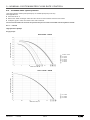
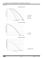
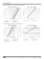
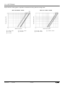
7 - APPLICATION DATA ............................................................................................................................................................. 38
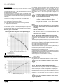
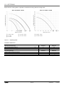
7.1 - Operating range ................................................................................................................................................................ 38
7.2 - Minimum heat transfer uid ow rate (units without factory-tted hydraulic module) ........................................................... 40
7.3 - Maximum energy transfer uid ow rate (units without factory-tted hydraulic module) ................................................... 40
7.4 - Variable ow water type heat exchanger (units without factory-tted hydraulic module) ................................................. 40
7.5 - Water exchanger minimum water volume and ow rate ................................................................................................... 40
7.6 - Maximum system water volume ........................................................................................................................................ 42
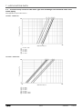
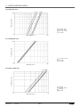
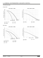
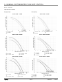
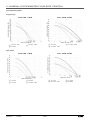
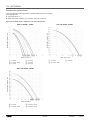
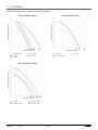
7.7 - Pressure drop curves for the water type heat exchanger and standard water inlet/outlet piping ...................................... 43
8 - WATER CONNECTIONS ....................................................................................................................................................... 46
8.1 - Operating precautions and recommendations .................................................................................................................. 46
8.2 - Hydraulic connections ....................................................................................................................................................... 47
8.3 - Hydraulic connections for ILD 2300R-4000R units: .......................................................................................................... 49
8.4 - Flow rate detection ............................................................................................................................................................ 51
8.5 - Cavitation protection (with hydraulic module option) ......................................................................................................... 51
8.6 - Backup electrical heaters .................................................................................................................................................. 51
8.7 - Frost protection ................................................................................................................................................................. 51
9 - NOMINAL SYSTEM WATER FLOW RATE CONTROL ........................................................................................................ 53
9.1 - Units without hydraulic module ......................................................................................................................................... 53
9.2 - Units with hydraulic module and xed-speed pump .......................................................................................................... 53
9.3 - Units with hydraulic module and variable-speed pump – Pressure dierential control ..................................................... 54
9.4 - Units with hydraulic module and variable-speed pump – Temperature dierential control ............................................... 55
9.5 - Units with hydraulic module and variable-speed pump - Setting a xed ow rate for the system ..................................... 55
9.6 - Available static system pressure ....................................................................................................................................... 56
EN-3 AQUACIATPOWER™ LD/ILD

The illustrations in this document are for illustrative purposes only and not part of any oer for sale or contract. The manufacturer reserves the right to change the design
at any time without notice.
This manual applies to the following units:
LD chiller with fans and xed-speed pumps (as standard) or fans and variable-speed pumps (optional), R32 refrigerant
(A2L uid)
ILD reversible heat pump with fans and xed-speed pumps (as standard) or fans and variable-speed pumps (optional),
R32 refrigerant (A2L uid)
For the operation of the control please refer to the LD/ILD control manual.
CONTENTS
10 - SYSTEM START-UP ........................................................................................................................................................... 61
10.1 - Checks before system start-up........................................................................................................................................ 61
10.2 - Commissioning ................................................................................................................................................................ 61
10.3 - Essential points to check ................................................................................................................................................. 62
11 - MAIN COMPONENTS OF THE UNIT AND OPERATING CHARACTERISTICS ................................................................ 63
11.1 - Compressors ................................................................................................................................................................... 63
11.2 - Lubricant ......................................................................................................................................................................... 63
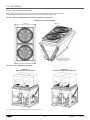
11.3 - Air-cooled exchanger ...................................................................................................................................................... 63
11.4 - Fans ................................................................................................................................................................................. 64
11.5 - Electronic expansion valve (EXV) ................................................................................................................................... 65
11.6 - Moisture indicator ............................................................................................................................................................ 65
11.7 - Dehumidier lter ............................................................................................................................................................. 65
11.8 - Refrigerant accumulator with built-in dehumidier lter ................................................................................................... 65
11.9 - Water type heat exchanger.............................................................................................................................................. 65
11.10 - Refrigerant ..................................................................................................................................................................... 65
11.11 - High-pressure safety pressostat .................................................................................................................................... 65
11.12 - Variable frequency drive ................................................................................................................................................ 65
11.13 - Fan arrangement ........................................................................................................................................................... 66
11.14 - Fan stages ..................................................................................................................................................................... 68
11.15 - Variable-speed fans (LD/ILD units) ................................................................................................................................ 68
11.16 - Connect Touch control ................................................................................................................................................... 68
12 - OPTIONS ............................................................................................................................................................................. 69
12.1 - Tables of options ............................................................................................................................................................. 69
12.2 - Description ...................................................................................................................................................................... 72
13 - STANDARD MAINTENANCE ............................................................................................................................................ 106
13.1 - Level 1 maintenance ..................................................................................................................................................... 106
13.2 - Level 2 maintenance ..................................................................................................................................................... 106
13.3 - Level 3 maintenance ..................................................................................................................................................... 107
13.4 - Tightening the electrical connections ............................................................................................................................ 108
13.5 - Tightening torques for the main fastenings ................................................................................................................... 108
13.6 - Air-cooled exchanger..................................................................................................................................................... 109
13.7 - Water type heat exchanger ........................................................................................................................................... 109
13.8 - Variable frequency drive ................................................................................................................................................ 109
13.9 - Refrigerant volume ........................................................................................................................................................ 109
13.10 - Refrigerant properties...................................................................................................................................................110
14 - FINAL SHUT-DOWN ...........................................................................................................................................................111
14.1 - Shutting down.................................................................................................................................................................111
14.2 - Recommendations for disassembly ...............................................................................................................................111
14.3 - Fluids to be recovered for treatment ..............................................................................................................................111
14.4 - Materials to be recovered for recycling ..........................................................................................................................111
14.5 - Waste Electrical and Electronic Equipment (WEEE) ......................................................................................................111
15 - UNIT START-UP CHECKLIST FOR INSTALLERS PRIOR TO CONTACTING THE MANUFACTURER .........................112
AQUACIATPOWER™ LD/ILD EN-4

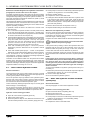
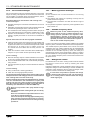
1 - INTRODUCTION AND SAFETY INSTRUCTIONS
The units are designed to cool water (for coolers) and cool or reheat water (for reversible heat pumps) for the air conditioning and
heating of buildings and industrial processes.
They are designed to provide a very high level of safety and reliability, making installation, start-up, operation and maintenance
easier and safer.
They will provide safe and reliable service if used within their application ranges.
For all safety instructions, please refer to the safety manual. A paper version is delivered with the machine, the digital version is
available in the same place as the IOM, (contact your local distributor).
In addition to this safety manual, the manufacturer states that the unit is designed for a maximum number of 120,000 start-ups.
This product contains uorinated greenhouse gases governed by the Kyoto protocol (1997) and covered by European regulation
517/2014 on uorinated greenhouse gases (Annex I):
Refrigerant type: R32
Global Warming Potential (GWP): 675 (as per AR4)
2 - RECEIPT OF GOODS
2.1 - Checking the equipment received
Check that the unit and the accessories have not been damaged during transport and that no parts are missing. If the unit and the
accessories have been damaged or the shipment is incomplete, send a claim to the shipping company.
Compare the name plate data with the order.
The name plate is attached in two places to the unit:
On one side of the unit exterior,
On the inside of the electrical panel door.
EN-5 AQUACIATPOWER™ LD/ILD

3 - HANDLING AND POSITIONING
3.1 - Handling
Carrier strongly recommends employing a specialised company
to unload the machine.
Do not remove the subbase or the packaging until the unit is in
its nal position.
These units can be safely moved by trained personnel with a
fork lift truck with the correct capacity for the dimensions and
weight of the unit, as long as the forks are positioned in the
location and direction shown on the unit.
The units can also be lifted with slings, using only the designated
lifting points marked on the unit (labels on the chassis and a label
with all unit handling instructions, attached to the unit).
Use slings with the correct capacity, and follow the lifting
instructions on the certied dimensional drawings supplied.
Only attach slings to the clearly marked points on
the unit provided for this purpose.
It is advisable to protect coils against crushing while a unit is
being moved. Use struts or a lifting beam to spread the slings
above the unit. Do not tilt the unit more than 15°.
Safety when lifting can only be guaranteed if all these instructions
are followed. Otherwise, there is a risk of equipment damage or
injury to personnel.
3.2 - Positioning
The unit must be installed in a place that is not accessible to the
public, or is protected against access by unauthorised persons.
The machine is designed to be installed outdoors.
More more details on the various installation scenarios, refer to
the installation guide for A2L refrigerants.
For extra-high units, the unit environment must permit easy
access for maintenance operations.
For the centre of gravity coordinates, the position of the unit
mounting holes, and the weight distribution points, refer to the
certied dimensional drawings. Ensure the free space shown in
the dimensional drawings is respected to facilitate maintenance
and connection.
The typical applications of these units are cooling and heating,
which do not require earthquake resistance. Earthquake
resistance has not been veried.
Before positioning the device, check that:
The chosen location can support the weight of the unit, or that
the appropriate reinforcement measures have been taken.
The unit is installed level on an even surface (maximum
tolerance is 5 mm along both axes).
If the support structure is sensitive to vibration and/or noise
transmission it is advisable to insert anti-vibration mounts
(elastomer mounts or metal springs) between the unit and the
structure. Selection of these devices is based on the system
characteristics and the comfort level required and should be
made by technical specialists.
There is adequate space above and around the unit for air to
circulate and for access to the components (see dimensional
drawings).
The number of support points is adequate and that they are
in the right places.
The unit must be installed on a plinth designed to collect then
drain the water produced by the reversible units during the
defrost cycles.
The location is not subject to ooding.
Avoid installing the unit where snow is likely to accumulate
(in areas subject to long periods of sub-zero temperatures,
the unit should be raised).
The wind may aect the operation and performances of
machines; baes may be necessary to protect the unit from
strong prevailing winds. These must not restrict the unit's air
ow.
Before lifting the unit, check that all enclosure
and set down the unit with great care. Tilting and
jarring can damage the unit and impair unit
operation.
Never apply pressure or leverage to any of the unit's
panels or uprights; only the base of the unit frame
is designed to withstand such stresses. No force or
effort must be applied to pressurised parts,
especially via pipes connected to the water type
module if the unit is equipped with this). The
pump does not support the weight of the pipes.
All welding operations (connection to the hydraulic network) must
be performed by qualied welders. The Victaulic® connection or
the counter-ange must be removed before welding as a matter
of course.
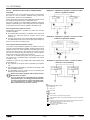
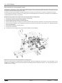
POWER ILD
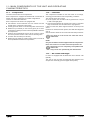
In some cases, uprights are added for transporting and handling
the unit. The uprights must be removed if necessary for access
or connection.
Follow the disassembly procedure indicated in the
disassembly instructions.
Undo the bolt (3).
Remove the upright (2).
Remove the plate (1).
BD
C
Keep the uprights following start-up and ret them when moving
the unit.
AQUACIATPOWER™ LD/ILD EN-6

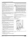
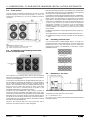
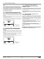
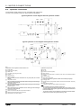
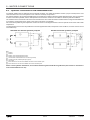
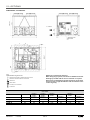
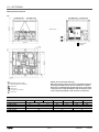
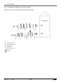
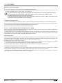
4 - DIMENSIONS, CLEARANCES, MINIMUM INSTALLATION DISTANCES
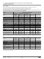
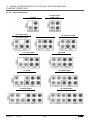
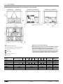
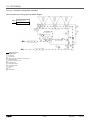
4.1 - LD and ILD dimensions without water buffer tank module
LD and ILD 602R to 2000R
Electrical power
connection
2324 HT
2253 HT
1500
1500
1500 2200
B
B
B
BC
Length (see following unit model table)
Unit model
POWER LD 602R to 1100R 1200R to
1600R
1750R to
2000R
2200R to
2650R -2800R to
3500R -
POWER ILD 602R to 1000R 1150R to
1500R
1600R to
2000R -2300R to
3000R -3200R to
4000R
2410 3604 4797 5992 7708 7185 10096
Key:
All dimensions are given in mm.
NOTE: Non-contractual drawings.
drawings provided with the unit or available on request.
Refer to the nameplate for the machine weight.
centre of gravity, hydraulic and electrical connections.
B
Clearances required for maintenance and air ow
C
Clearance recommended for coil removal
Water inlet
Water outlet
Air outlet, do not obstruct
Control box
EN-7 AQUACIATPOWER™ LD/ILD

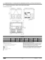
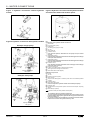
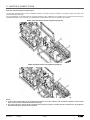
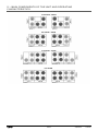
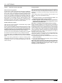
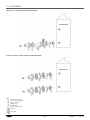
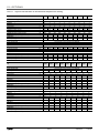
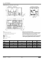
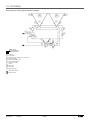
ILD 2300R to 4000R / Without hydraulic module
Electrical power
connection
2324 HT
2200
2200
D
AB
500
min
1500
1500
2353 HT
C
E
ILD 2300R to
3000R
3200R to
4000R
7680 10068
357 357
251 251
544 544
597 597
5” 5”
B
B
BB
C
C
ILD 2300R to 4000R / With hydraulic module
Electrical power
connection
2200
2353HT D
A
C
F
B
E
500
min
1500
1500
2324 HT
2200
ILD 2300R to
3000R
3200R to
4000R
7680 10068
290 251
254 254
640 640
516 509
265 265
5” 5”
B
B
BB
C
C
Key:
All dimensions are given in mm.
NOTE: Non-contractual drawings.
drawings provided with the unit or available on request.
Refer to the nameplate for the machine weight.
centre of gravity, hydraulic and electrical connections.
B
Clearances required for maintenance and air ow
C
Clearance recommended for coil removal
Water inlet
Water outlet
Air outlet, do not obstruct
Control box
4 - DIMENSIONS, CLEARANCES, MINIMUM INSTALLATION DISTANCES
AQUACIATPOWER™ LD/ILD EN-8

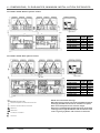
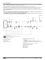
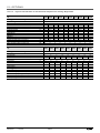
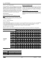
4.2 - LD and ILD dimensions with water buffer tank module
Electrical power connection
Length (see following unit model table)
Main hydraulic connection
2324 HT
2253 HT
1500
1500
1500
2200
B
B
B
CB
Unit model
POWER LD 602R to 1100R 1200R to 1600R 1750R to 2000R 2200R to 2650R 2800R to 3500R
POWER ILD 602R to 1000R 1150R to 1500R 1600R to 2000R - -
3604 4798 5992 7186 8379
Key:
All dimensions are given in mm.
NOTE: Non-contractual drawings.
drawings provided with the unit or available on request.
Refer to the nameplate for the machine weight.
centre of gravity, hydraulic and electrical connections.
B
Clearances required for maintenance and air ow
C
Clearance recommended for coil removal
Water inlet
Water outlet
Air outlet, do not obstruct
Control box
4 - DIMENSIONS, CLEARANCES, MINIMUM INSTALLATION DISTANCES
EN-9 AQUACIATPOWER™ LD/ILD

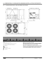
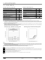
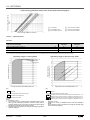
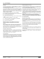
4.3 - Free spaces
The free spaces presented are determined in order to ensure
sufficient working and manoeuvring space to carry out
maintenance operations on the unit in suitable ergonomic
conditions
2200
2253 HT
1500
15001500
B
B C
B
B
Key:
All dimensions are given in mm.
B
Clearances required for maintenance and air ow
C
Clearance recommended for coil removal
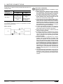
4.4 - Positioning of potentially ammable
zones around the unit
Electrical cabinet
side
60 cm
The complete unit, including all the options and accessories
which are provided by the manufacturer, have been certied for
use with an A2L refrigerant.
To ensure this, the manufacturer complies with EN 378-2 §6.2.14
and has dened a potentially ammable zone using EN 60079-
10-1 in order to identify where no sources of ignition must be
present. The manufacturer has then designed the machine so
that, if the unit is used in the manner for which it has been
designed, there are no internal sources of ignition in the
potentially ammable zone inside the machine.
Therefore, the only residual risk is that a source of ignition is
introduced into the potentially ammable zone by the user.
This is why the manufacturer has decided to show the potentially
ammable zone around the machine (see the diagram above)
into which the user must not introduce any sources of ignition.
This indication is only provided to help our customers to identify
the limits of the ammability risk.
However, the machine itself does not present any risk of
explosion connected to the use of A2L refrigerant.
Note (the following information is provided by the manufacturer
for information purposes only. The application of the following
directives is the sole responsibility of the user):
In compliance with the directives 2009/104/EC and 1999/92/EC,
these zones may be qualied as ATEX zones by the user on the
basis of their own risk analysis, for which they alone remain
responsible. In accordance with the denition given by Annex I
of the directive 1999/92/EC, this zone may be classied as zone
2 since it may consist of a location where an explosive
atmosphere consisting of a mixture of air and flammable
substances in the form of a gas is not liable to occur during
normal operation or, if it does occur, it only occurs for a short
period of time.
If additional equipment is required (motorised valve, pump, etc.),
it must be:
Installed outside of the dened potentially ammable zone.
Certied as not being a source of ignition for the refrigerant
used.
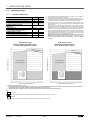
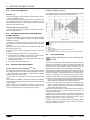
4.5 - Installing several units
It is recommended to install multiple units in a single row,
arranged as shown in the example below, to avoid recycling air
between the units. If the floor space does not allow this
arrangement, contact your distributor to assess the various
installation options.
1500 mm min.
1500 mm min.
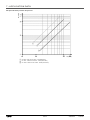
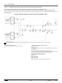
4.6 - Distance to the wall
Anti-vibration
Mounts
To guarantee correct operation in most cases:
If h < H, S minimum = 3 m
If h > H or S < 3 m, contact your distributor to assess the various
installation options.
4 - DIMENSIONS, CLEARANCES, MINIMUM INSTALLATION DISTANCES
AQUACIATPOWER™ LD/ILD EN-10

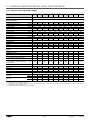
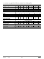
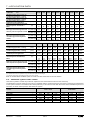
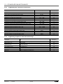
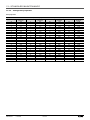
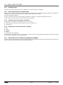
5 - PHYSICAL AND ELECTRICAL DATA FOR THE UNITS
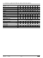
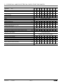
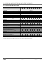
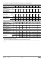
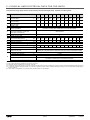
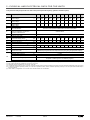
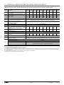
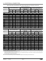
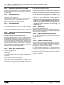
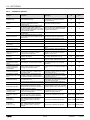
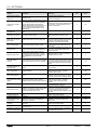
5.1 - Physical data LD 602R - 3500R
POWER LD 0602R-A 0650R-A 0750R-A 0900R-A 1100R-A 1200R-A 1350R-A 1400R-A 1600R-A 1750R-A
Sound levels
Unit + High temperature option/Nominal
high performance
Sound power(1) dB(A) 91,0 91,5 91,5 92,0 92,0 93,0 93,0 93,5 93,5 94,0
Sound pressure at 10 m(2) dB(A) 58,5 59,5 59,5 60,0 60,0 60,5 60,5 61,0 61,5 61,5
Standard unit
Sound power(1) dB(A) 88,5 89,0 89,0 89,5 89,5 90,5 90,5 91,0 91,0 91,5
Sound pressure at 10 m(2) dB(A) 56,5 57,0 57,0 57,5 57,5 58,5 58,5 59,0 58,5 59,5
Unit + Very Low Noise option
Sound power(1) dB(A) 85,5 85,5 85,5 86,5 86,5 87,5 87,5 88,0 88,0 88,5
Sound pressure at 10 m(2) dB(A) 53,0 53,5 53,5 54,5 54,5 55,5 55,5 55,5 56,0 56,0
Unit + Ultra Low Noise option
Sound power(1) dB(A) 83,5 83,5 83,5 84,5 84,5 85,5 85,5 86,0 86,0 86,5
Sound pressure at 10 m(2) dB(A) 51,5 51,5 51,5 52,5 52,5 53,5 53,5 53,5 53,5 54,5
Dimensions
Standard unit
Length mm 2410 2410 2410 2410 2410 3604 3604 3604 3604 4798
Width mm 2253 2253 2253 2253 2253 2253 2253 2253 2253 2253
Height mm 2324 2324 2324 2324 2324 2324 2324 2324 2324 2324
option
Length mm 3604 3604 3604 3604 3604 4798 4798 4798 4798 5992
Operating weight
Standard unit kg 1349 1397 1397 1521 1556 1995 2049 2211 2269 2697
Unit + Ultra Low Noise option kg 1453 1501 1501 1656 1690 2153 2208 2394 2452 2904
Unit + Ultra Low Noise + HP dual-
pump hydraulic module option kg 1588 1636 1636 1791 1837 2302 2403 2589 2646 3138
Unit + Ultra Low Noise + HP dual-
pump hydraulic module + Buer tank
module option
kg 2571 2619 2619 2774 2819 3288 3389 3575 3632 4131
Compressors Hermetic Scroll 48.3 r/s
Circuit A 1112222333
Circuit B 2 2 2 2 2 3 3 3 3 4
Number of power stages 3 3 3 4 4 5 5 6 6 7
Unit PED category III III III III III III III III III IV
Refrigerant R-32 / A2L/ GWP= 675 in accordance with ARI4
Circuit A kg 6,3 9,4 9,4 11,1 11,5 12,2 13,0 17,7 18,5 18,8
tCO2e4,2 6,3 6,3 7,5 7,8 8,2 8,8 11,9 12,5 12,7
Circuit B kg 11,1 11,1 11,1 11,1 11,5 17,1 17,9 18,5 19,3 24,5
tCO2e7,5 7,5 7,5 7,5 7,8 11,5 12,0 12,5 13,0 16,5
(1) In dB ref=10-12 W, (A) weighting. Declared dual-number noise emission value in accordance with ISO 4871 with an uncertainty of +/-3 dB(A). Measured in accordance
with ISO 9614-1 and certied by Eurovent.
(2) In dB ref 20 µPa, (A) weighting. Declared dual-number noise emission value in accordance with ISO 4871 with an uncertainty of +/-3 dB(A). For information,
calculated from the sound power Lw(A).
(3) Values are guidelines only. Refer to the unit name plate.
EN-11 AQUACIATPOWER™ LD/ILD

POWER LD 0602R-A 0650R-A 0750R-A 0900R-A 1100R-A 1200R-A 1350R-A 1400R-A 1600R-A 1750R-A
Oil
Circuit A l6,6 6,6 6,6 13,2 13,2 13,2 13,2 19,8 19,8 19,8
Circuit B l 13,2 13,2 13,2 13,2 13,2 19,8 19,8 19,8 19,8 26,4
Capacity control Connect’Touch
Minimum capacity % 33 33 33 25 25 20 20 17 17 14
Condenser All-aluminium micro-channel coils (MCHE)
Fans Axial with rotating impeller
Standard unit
Quantity 3 4 4 4 4 5 5 6 6 7
Maximum total air ow l/s 11790 15720 15720 15720 15720 19650 19650 23580 23580 27510
Maximum rotation speed r/s 12 12 12 12 12 12 12 12 12 12
Evaporator Dual-circuit plate heat exchanger
Water volume l 15 15 15 19 27 27 35 44 44 44
Max. water-side operating pressure
without hydraulic module kPa 1000 1000 1000 1000 1000 1000 1000 1000 1000 1000
Pump, Victaulic screen lter, relief valve, water and air vent valve, pressure sensors
Pump Centrifugal pump, monocell, 48.3 r/s, low- or high-pressure (as required),
single or dual (as required)
Expansion tank volume (option) l 50 50 50 50 50 80 80 80 80 80
Buer tank volume (optional) l 550 550 550 550 550 550 550 550 550 550
Max. water-side operating pressure
with hydraulic module kPa 400 400 400 400 400 400 400 400 400 400
Water connections with or without
hydraulic module Victaulic® type
Connections inches 3 3 3 3 3 4 4 4 4 4
External diameter mm 88,9 88,9 88,9 88,9 88,9 114,3 114,3 114,3 114,3 114,3
Casing paint colour Colour code RAL 7035 & 7024
5 - PHYSICAL AND ELECTRICAL DATA FOR THE UNITS
AQUACIATPOWER™ LD/ILD EN-12

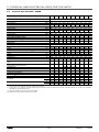
POWER LD 1800R-A 2000R-A 2200R-A 2400R-A 2650R-A 2800R-A 2950R-A 3200R-A 3500R-A
Sound levels
Unit + High temperature option/Nominal high
performance
Sound power(1) dB(A) 94,0 94,5 97,5 97,5 98,0 98,0 98,5 98,5 99,0
Sound pressure at 10 m(2) dB(A) 61,5 62,0 65,0 65,0 66,0 65,0 66,0 66,0 66,5
Standard unit
Sound power(1) dB(A) 91,5 92,0 96,5 96,5 97,0 97,0 97,5 97,5 98,0
Sound pressure at 10 m(2) dB(A) 59,0 60,0 64,0 64,0 64,5 65,0 65,0 65,0 65,5
Unit + Very Low Noise option
Sound power(1) dB(A) 88,5 89,0 92,5 92,5 93,0 93,0 93,5 93,5 94,5
Sound pressure at 10 m(2) dB(A) 56,5 57,0 60,5 60,0 60,5 60,0 61,0 60,5 61,5
Unit + Ultra Low Noise option
Sound power(1) dB(A) 86,5 87,0 90,0 90,0 90,5 90,5 90,5 90,5 91,0
Sound pressure at 10 m(2) dB(A) 54,0 55,0 57,5 57,5 58,0 58,0 57,5 58,0 58,5
Dimensions
Standard unit
Length mm 4798 4798 5992 5992 5992 7186 7186 7186 7186
Width mm 2253 2253 2253 2253 2253 2253 2253 2253 2253
Height mm 2324 2324 2324 2324 2324 2324 2324 2324 2324
Length mm 5992 5992 7186 7186 7186 8380 8380 8380 8380
Operating weight
Standard unit kg 2722 2927 3265 3511 3511 4042 4042 4291 4291
Unit + Ultra Low Noise option kg 2930 3158 3434 3703 3703 4260 4260 4535 4535
Unit + Ultra Low Noise + HP dual-pump
hydraulic module option kg 3164 3430 3743 4013 4013 4650 4650 4925 4925
Unit + Ultra Low Noise + HP dual-pump
hydraulic module + Buer tank module option kg 4156 4421 4750 5020 5020 5671 5671 5946 5946
Compressors Hermetic Scroll 48.3 r/s
Circuit A 342333344
Circuit B 4 4 3 3 3 4 4 4 4
Number of power stages 7 8 5 6 6 7 7 8 8
Unit PED category IV IV III III III IV IV IV IV
Refrigerant R-32 / A2L/ GWP= 675 in accordance with ARI4
Circuit A kg 19,1 24,4 23,0 24,5 24,5 27,3 27,3 30,4 30,4
tCO2e12,9 16,5 15,5 16,5 16,5 18,4 18,4 20,5 20,5
Circuit B kg 24,9 25,4 24,5 24,5 24,5 30,4 30,4 30,4 30,4
tCO2e16,8 17,1 16,5 16,5 16,5 20,5 20,5 20,5 20,5
(1) In dB ref=10-12 W, (A) weighting. Declared dual-number noise emission value in accordance with ISO 4871 with an uncertainty of +/-3 dB(A). Measured in accordance
with ISO 9614-1 and certied by Eurovent.
(2) In dB ref 20 µPa, (A) weighting. Declared dual-number noise emission value in accordance with ISO 4871 with an uncertainty of +/-3 dB(A). For information,
calculated from the sound power Lw(A).
(3) Values are guidelines only. Refer to the unit name plate.
5 - PHYSICAL AND ELECTRICAL DATA FOR THE UNITS
EN-13 AQUACIATPOWER™ LD/ILD

POWER LD 1800R-A 2000R-A 2200R-A 2400R-A 2650R-A 2800R-A 2950R-A 3200R-A 3500R-A
Oil
Circuit A l19,8 26,4 13,2 19,8 19,8 19,8 19,8 26,4 26,4
Circuit B l 26,4 26,4 19,8 19,8 19,8 26,4 26,4 26,4 26,4
Capacity control Connect’Touch
Minimum capacity % 14 13 20 17 17 14 14 13 13
Condenser All-aluminium micro-channel coils (MCHE)
Fans Axial with rotating impeller
Standard unit
Quantity 7 8 9 10 10 11 11 12 12
Maximum total air ow l/s 27510 31440 35370 39300 39300 43230 43230 47160 47160
Maximum rotation speed r/s 12 12 12 12 12 12 12 12 12
Evaporator Dual-circuit plate heat exchanger
Water volume l 47 53 73 73 73 84 84 84 84
Max. water-side operating pressure without
hydraulic module kPa 1000 1000 1000 1000 1000 1000 1000 1000 1000
Pump, Victaulic screen lter, relief valve, water and air vent valve, pressure sensors
Pump Centrifugal pump, monocell, 48.3 r/s, low- or high-pressure (as required),
single or dual (as required)
Expansion tank volume (Option) l 80 80 80 80 80 80 80 80 80
Buer tank volume (optional) l 550 550 550 550 550 550 550 550 550
Max. water-side operating pressure with
hydraulic module kPa 400 400 400 400 400 400 400 400 400
Water connections with or without
hydraulic module Victaulic® type
Connections inches 4 4 5 5 5 5 5 5 5
External diameter mm 114,3 114,3 139,7 139,7 139,7 139,7 139,7 139,7 139,7
Casing paint colour Colour code RAL 7035 & 7024
5 - PHYSICAL AND ELECTRICAL DATA FOR THE UNITS
AQUACIATPOWER™ LD/ILD EN-14

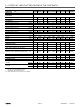
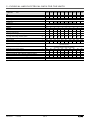
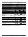
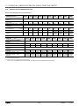
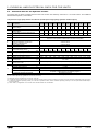
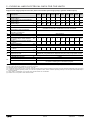
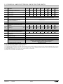
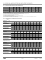
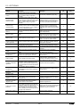
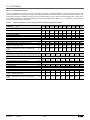
5.2 - Physical data ILD 602R - 4000R
POWER ILD 0602R 0700R 0800R 0900R 1000R 1150R 1250R 1400R 1500R 1600R
Sound levels
Unit + High temperature option/Nominal high performance
Sound power(1) dB(A) 90,5 91,0 91,5 92,0 92,0 93,0 93,5 94,0 94,0 94,5
Sound pressure at 10 m(2) dB(A) 58,5 59,0 59,5 60,0 60,0 61,0 61,5 62,0 62,0 62,0
Standard unit
Sound power(1) dB(A) 88,0 88,5 89,0 89,5 89,5 90,5 91,0 91,5 91,5 92,0
Sound pressure at 10 m(2) dB(A) 55,5 56,0 56,5 57,0 57,0 58,0 58,5 59,5 59,5 60,0
Unit + Very Low Noise option
Sound power(1) dB(A) 85,0 86,0 86,5 87,0 87,0 88,0 88,0 89,0 89,0 89,5
Sound pressure at 10 m(2) dB(A) 53,0 53,5 54,0 54,5 54,5 55,5 55,5 56,5 56,5 57,0
Unit + Ultra Low Noise option
Sound power(1) dB(A) 83,0 84,0 84,5 85,0 85,0 86,0 86,0 86,5 87,0 87,5
Sound pressure at 10 m(2) dB(A) 51,0 52,0 52,5 53,0 53,0 54,0 54,0 54,5 55,0 55,5
Dimensions
Standard unit
Length mm 2410 2410 2410 2410 2410 3604 3604 3604 3604 4798
Width mm 2253 2253 2253 2253 2253 2253 2253 2253 2253 2253
Height mm 2324 2324 2324 2324 2324 2324 2324 2324 2324 2324
mm 3604 3604 3604 3604 3604 4798 4798 4798 4798 5992
Length mm 3604 3604 3604 3604 3604 4798 4798 4798 4798 5992
Operating weight
Standard unit kg 1569 1575 1784 1811 1817 2394 2452 2672 2678 3154
Unit + Ultra Low Noise option kg 1672 1678 1918 1946 1952 2552 2611 2855 2861 3361
Unit + Ultra Low Noise + HP dual-pump hydraulic module
option kg 1808 1814 2065 2092 2098 2747 2806 3089 3095 3595
Unit + Ultra Low Noise + HP dual-pump hydraulic module +
Water buer tank module option kg 2791 2797 3048 3075 3081 3756 3815 4098 4104 4595
Compressors Hermetic Scroll 48.3 r/s
Circuit A/C 1122222223
Circuit B/D 2 2 2 2 2 3 3 4 4 4
Number of power stages 3 3 4 4 4 5 5 6 6 7
Unit PED category III III III III III III IV IV IV IV
Refrigerant R-32 / A2L/ GWP= 675 in accordance with ARI4
Circuit A/C kg 10,5 10,5 16,0 16,0 16,0 16,0 18,0 18,0 18,0 29,0
tCO2e7,1 7,1 10,8 10,8 10,8 10,8 12,2 12,2 12,2 19,6
Circuit B/D kg 16,0 16,0 16,0 16,0 16,0 28,5 28,5 34,0 34,0 34,5
tCO2e10,8 10,8 10,8 10,8 10,8 19,2 19,2 23,0 23,0 23,3
(1) In dB ref=10-12 W, (A) weighting. Declared dual-number noise emission value in accordance with ISO 4871 with an uncertainty of +/-3 dB(A). Measured in accordance
with ISO 9614-1 and certied by Eurovent. Cooling mode operation.
(2) In dB ref 20 µPa, (A) weighting. Declared dual-number noise emission value in accordance with ISO 4871 with an uncertainty of +/-3 dB(A). For information,
calculated from the sound power Lw(A).
(3) Values are guidelines only. Refer to the unit name plate.
(a) Modules 1 and 2 only relate to sizes 2300R to 4000R.
5 - PHYSICAL AND ELECTRICAL DATA FOR THE UNITS
EN-15 AQUACIATPOWER™ LD/ILD

POWER ILD 0602R 0700R 0800R 0900R 1000R 1150R 1250R 1400R 1500R 1600R
Oil
Circuit A/C l6,6 6,6 13,2 13,2 13,2 13,2 13,2 13,2 13,2 22,8
Circuit B/D l 13,2 13,2 13,2 13,2 13,2 22,8 22,8 30,4 30,4 30,4
Capacity control Connect’Touch
Minimum capacity % 33 33 25 25 25 20 20 17 17 14
Condenser Grooved copper tubes and aluminium ns
Fans Axial with rotating impeller
Standard unit
Quantity 3 3 4 4 4 5 5 6 6 7
Maximum total air ow l/s 11790 11790 15720 15720 15720 19650 19650 23580 23580 27510
Maximum rotation speed r/s 12 12 12 12 12 12 12 12 12 12
Maximum total air ow
with high rated energy eciency option l/s 14460 14460 19280 19280 19280 24100 24100 28920 28920 33740
Maximum rotation speed
with high rated energy eciency option r/s 16 16 16 16 16 16 16 16 16 16
Evaporator Dual-circuit plate heat exchanger
Water volume l 16,2 16,2 16,2 20,7 20,7 38,7 48,6 48,6 48,6 48,6
Max. water-side operating pressure without hydraulic module kPa 1000 1000 1000 1000 1000 1000 1000 1000 1000 1000
Pump, Victaulic screen lter, relief valve, water and air vent valve,
pressure sensors
Pump Centrifugal pump, monocell, 48.3 r/s, low- or high-pressure (as
required), single or dual (as required)
Expansion tank volume (Option) l 50 50 50 50 50 80 80 80 80 80
Buer tank volume (optional) l 550 550 550 550 550 550 550 550 550 550
Max. water-side operating pressure with hydraulic module kPa 400 400 400 400 400 400 400 400 400 400
Water connections with or without hydraulic module Victaulic® type
Module 1/Module 2 connections(a) inches3333344444
Module 1/Module 2 external diameter(a) mm 88,5 88,6 88,7 88,8 88,9 114,3 114,4 114,5 114,6 114,7
Casing paint colour Colour code RAL 7035 & 7024
(a) Modules 1 and 2 only relate to sizes 2300R to 4000R.
5 - PHYSICAL AND ELECTRICAL DATA FOR THE UNITS
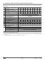
AQUACIATPOWER™ LD/ILD EN-16

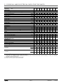
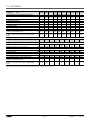
POWER ILD 1750R 2000R 2300R 2500R 2800R 3000R 3200R 3500R 4000R
Sound levels
Unit + High temperature option/Nominal high performance
Sound power(1) dB(A) 94,5 95,0 96,0 96,5 97,0 97,0 97,5 97,5 98,0
Sound pressure at 10 m(2) dB(A) 62,0 62,5 64,0 64,0 64,5 65,0 65,0 65,0 65,0
Standard unit
Sound power(1) dB(A) 92,5 93,0 93,5 94,0 94,5 94,5 95,0 95,5 96,0
Sound pressure at 10 m(2) dB(A) 60,0 60,5 61,0 61,5 62,5 62,5 63,0 63,0 63,5
Unit + Very Low Noise option
Sound power(1) dB(A) 90,0 90,0 91,0 91,0 92,0 92,0 92,5 93,0 93,0
Sound pressure at 10 m(2) dB(A) 57,5 57,5 58,5 58,5 59,5 59,5 60,0 60,5 60,5
Unit + Ultra Low Noise option
Sound power(1) dB(A) 87,5 88,0 89,0 89,0 89,5 90,0 90,5 90,5 91,0
Sound pressure at 10 m(2) dB(A) 55,5 56,0 57,0 57,0 57,5 58,0 58,5 58,5 59,0
Dimensions
Standard unit
Length mm 4798 4798 7708 7708 7708 7708 10096 10096 10096
Width mm 2253 2253 2253 2253 2253 2253 2253 2253 2253
Height mm 2324 2324 2324 2324 2324 2324 2324 2324 2324
mm 5992 5992 5992 5992 5992 5992 5992 5992 5992
Length mm 5992 5992 - - - - - - -
Operating weight
Standard unit kg 3180 3430 4787 4905 5344 5356 6308 6360 6859
Unit + Ultra Low Noise option kg 3387 3661 5104 5222 5710 5722 6722 6774 7322
Unit + Ultra Low Noise + HP dual-pump hydraulic module option kg 3658 3932 5494 5611 6178 6190 7191 7317 7865
Unit + Ultra Low Noise + HP dual-pump hydraulic module + Water
buer tank module option kg 4658 4932 - - - - - - -
Compressors Hermetic Scroll 48.3 r/s
Circuit A/C 3 4 2/2 2/2 2/2 2/2 3/3 3/3 4/4
Circuit B/D 4 4 3/3 3/3 4/4 4/4 4/4 4/4 4/4
Number of power stages 7 8 10 10 12 12 14 14 16
Unit PED category IV IV III IV IV IV IV IV IV
Refrigerant R-32 / A2L/ GWP= 675 in accordance with ARI4
Circuit A/C
kg 29,0 35,0 16,0 /
16,0
18,0 /
18,0
18,0 /
18,0
18,0 /
18,0
29,0 /
29,0
29,0 /
29,0
35,0 /
35,0
tCO2e19,6 23,6 10,8 /
10,8
12,2 /
12,2
12,2 /
12,2
12,2 /
12,2
19,6 /
19,6
19,6 /
19,6
23,6 /
23,6
Circuit B/D
kg 35,0 35,0 28,5 /
28,5
28,5 /
28,5
34,0 /
34,0
34,0 /
34,0
34,5 /
34,5
35,0 /
35,0
35,0 /
35,0
tCO2e23,6 23,6 19,2 /
19,2
19,2 /
19,2
23,0 /
23,0
23,0 /
23,0
23,3 /
23,3
23,6 /
23,6
23,6 /
23,6
(1) In dB ref=10-12 W, (A) weighting. Declared dual-number noise emission value in accordance with ISO 4871 with an uncertainty of +/-3 dB(A). Measured in accordance
with ISO 9614-1 and certied by Eurovent. Cooling mode operation.
(2) In dB ref 20 µPa, (A) weighting. Declared dual-number noise emission value in accordance with ISO 4871 with an uncertainty of +/-3 dB(A). For information,
calculated from the sound power Lw(A).
(3) Values are guidelines only. Refer to the unit name plate.
(a) Modules 1 and 2 only relate to sizes 2300R to 4000R.
5 - PHYSICAL AND ELECTRICAL DATA FOR THE UNITS
EN-17 AQUACIATPOWER™ LD/ILD

POWER ILD 1750R 2000R 2300R 2500R 2800R 3000R 3200R 3500R 4000R
Oil
Circuit A/C l22,8 30,4 13,2 /
13,2
13,2 /
13,2
13,2 /
13,2
13,2 /
13,2
22,8 /
22,8
22,8 /
22,8
30,4 /
30,4
Circuit B/D l 30,4 30,4 22,8 /
22,8
22,8 /
22,8
30,4 /
30,4
30,4 /
30,4
30,4 /
30,4
30,4 /
30,4
30,4 /
30,4
Capacity control Connect’Touch
Minimum capacity % 14 13 10 10 8 8 7 7 6
Condenser Grooved copper tubes and aluminium ns
Fans Axial with rotating impeller
Standard unit
Quantity 7 8 10 10 12 12 14 14 16
Maximum total air ow l/s 27510 31440 39300 39300 47160 47160 55020 55020 62880
Maximum rotation speed r/s 12 12 12 12 12 12 12 12 12
Maximum total air ow
with high rated energy eciency option l/s 33740 38560 48200 48200 57840 57840 67480 67480 77120
Maximum rotation speed
with high rated energy eciency option r/s 16 16 16 16 16 16 16 16 16
Evaporator Dual-circuit plate heat exchanger
Water volume l 52,2 58,5 77,4 97,2 97,2 97,2 97,2 104,4 117
Max. water-side operating pressure without hydraulic module kPa 1000 1000 1000 1000 1000 1000 1000 1000 1000
Pump, Victaulic screen lter, relief valve, water and air vent
valve, pressure sensors
Pump Centrifugal pump, monocell, 48.3 r/s, low- or high-pressure (as
required), single or dual (as required)
Expansion tank volume (Option) l 80 80 - - - - - - -
Buer tank volume (optional) l 550 550 - - - - - - -
Max. water-side operating pressure with hydraulic module kPa 400 400 400 400 400 400 400 400 400
Water connections with or without hydraulic module Victaulic® type
Module 1/Module 2 connections(a) inches 4 4 4 / 4 4 / 4 4 / 4 4 / 4 4 / 4 4 / 4 4 / 4
Module 1/Module 2 external diameter(a) mm 114,8 114,9
114,3
/
114,3
114,3
/
114,3
114,3
/
114,3
114,3
/
114,3
114,3
/
114,3
114,3
/
114,3
114,3
/
114,3
Casing paint colour Colour code RAL 7035 & 7024
(a) Modules 1 and 2 only relate to sizes 2300R to 4000R.
5 - PHYSICAL AND ELECTRICAL DATA FOR THE UNITS
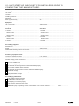
AQUACIATPOWER™ LD/ILD EN-18

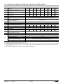
5.3 - Electrical data LD 602R - 3500R
POWER LD 0602R 0650R 0750R 0900R 1100R 1200R 1350R 1400R 1600R 1750R
Power circuit supply
Nominal voltage V-ph-Hz 400 - 3 - 50
Voltage range V 360 - 440
Control circuit supply 24 V via internal transformer
Circuit A&B kW 71,6 77,2 86,8 95,4 114,6 128,9 143,3 157,5 171,9 186,2
Displacement Power Factor (Cos Phi), standard unit 0,83 0,83 0,83 0,83 0,83 0,83 0,83 0,83 0,83 0,83
Standard unit A 123,9 134,4 151,0 165,2 198,4 223,1 248,0 272,7 297,6 322,3
Standard unit A 132,6 143,8 161,8 176,8 212,8 239 266 292,2 319,2 345,4
Standard unit A 300 347 364 341 411 436 461 485 510 535
Unit + Electronic soft starter option A 257 295 312 298 359 384 409 433 458 483
POWER LD 1800R 2000R 2200R 2400R 2650R 2800R 2950R 3200R 3500R
Power circuit supply
Nominal voltage V-ph-Hz 400 - 3 - 50
Voltage range V 360 - 440
Control circuit supply 24 V via internal transformer
Circuit A&B kW 200,6 229,2 246,7 271,9 295,3 316,7 328,4 361,4 392,6
Displacement Power Factor (Cos Phi), standard unit 0,83 0,83 0,83 0,83 0,83 0,83 0,83 0,83 0,83
Standard unit A 347,2 396,8 432,3 478,0 517,0 556,2 575,7 634,4 686,4
Standard unit A 372,4 425,6 464,8 514 556 598,2 619,2 682,4 738,4
Standard unit A 560 609 763 815 848 893 906 971 1017
Unit + Electronic soft starter option A 508 557 680 732 765 811 824 889 934
(1) Values at the unit's permanent maximum operating condition (as shown on the unit's nameplate).
(2) Values at the unit's maximum operating condition (as shown on the unit's nameplate).
(3) Maximum operating current of the smallest compressor(s) + fan current + locked rotor current of the largest compressor.
5 - PHYSICAL AND ELECTRICAL DATA FOR THE UNITS
EN-19 AQUACIATPOWER™ LD/ILD

5.4 - Electrical data ILD 602R - 4000R
POWER ILD 0602R 0700R 0800R 0900R 1000R 1150R 1250R 1400R 1500R 1600R
Power circuit supply
Nominal voltage V-ph-Hz 400 - 3 - 50
Voltage range V 360 - 440
Control circuit supply 24 V via internal transformer
Circuit A&B (Module 1/Module 2) (a) kW 71,6 81,2 95,4 105,0 114,6 133,7 143,3 162,3 171,9 186,2
Displacement Power Factor (Cos Phi), standard unit 0,83 0,83 0,83 0,83 0,83 0,83 0,83 0,83 0,83 0,83
Standard unit (Module 1/Module 2) (a) A123,9 140,5 165,2 181,8 198,4 231,4 248,0 281,0 297,6 322,3
Standard unit (Module 1/Module 2) (a) A135,6 151,6 180,8 196,8 212,8 250,0 266,0 303,2 319,2 348,4
Standard unit (Module 1/Module 2) (a) A299,8 355,3 341,1 394,4 411 444 460,6 493,6 510,2 534,9
Unit + Soft starter option
(Module 1 / Module 2) (a) A256,8 303 298 342 359 392 409 442 458 483
POWER ILD 1750R 2000R 2300R 2500R 2800R 3000R 3200R 3500R 4000R
Power circuit supply
Nominal voltage V-ph-Hz 400 - 3 - 50
Voltage range V 360 - 440
Control circuit supply 24 V via internal transformer
Circuit A&B (Module 1/Module 2) (a) kW 200,6 229,2 139,2 /
139,2
148,7 /
148,7
169,0 /
169,0
178,6 /
178,6
193,7 /
193,7
208,1 /
208,1
237,8 /
237,8
Displacement Power Factor (Cos Phi), standard unit 0,83 0,83 0,85 0,85 0,85 0,85 0,85 0,85 0,85
Standard unit (Module 1/Module 2) (a) A347,2 396,8 235,4 /
235,4
252 /
252
285,8 /
285,8
302,4 /
302,4
327,9 /
327,9
352,8 /
352,8
403,2 /
403,2
Standard unit (Module 1/Module 2) (a) A372,4 425,6 254 /
254
270 /
270
308 /
308
324 /
324
354 /
354
378 /
378
432 /
432
Standard unit (Module 1/Module 2) (a) A559,8 609,4 448 /
448
465 /
465
498 /
498
515 /
515
541 /
541
565 /
565
616 /
616
Unit + Soft starter option
(Module 1 / Module 2) (a) A 508 557 396 /
396
413 /
413
446 /
446
463 /
463
489 /
489
513 /
513
564 /
564
(1) Values at the unit's permanent maximum operating condition (as shown on the unit's nameplate).
(2) Values at the unit's maximum operating condition (as shown on the unit's nameplate).
(3) Maximum operating current of the smallest compressor(s) + fan current + locked rotor current of the largest compressor.
(a) Modules 1 and 2 only relate to sizes 2300R to 4000R.
5 - PHYSICAL AND ELECTRICAL DATA FOR THE UNITS
AQUACIATPOWER™ LD/ILD EN-20
Page is loading ...
Page is loading ...
Page is loading ...
Page is loading ...
Page is loading ...
Page is loading ...
Page is loading ...
Page is loading ...
Page is loading ...
Page is loading ...
Page is loading ...
Page is loading ...
Page is loading ...
Page is loading ...
Page is loading ...
Page is loading ...
Page is loading ...
Page is loading ...
Page is loading ...
Page is loading ...
Page is loading ...
Page is loading ...
Page is loading ...
Page is loading ...
Page is loading ...
Page is loading ...
Page is loading ...
Page is loading ...
Page is loading ...
Page is loading ...
Page is loading ...
Page is loading ...
Page is loading ...
Page is loading ...
Page is loading ...
Page is loading ...
Page is loading ...
Page is loading ...
Page is loading ...
Page is loading ...
Page is loading ...
Page is loading ...
Page is loading ...
Page is loading ...
Page is loading ...
Page is loading ...
Page is loading ...
Page is loading ...
Page is loading ...
Page is loading ...
Page is loading ...
Page is loading ...
Page is loading ...
Page is loading ...
Page is loading ...
Page is loading ...
Page is loading ...
Page is loading ...
Page is loading ...
Page is loading ...
Page is loading ...
Page is loading ...
Page is loading ...
Page is loading ...
Page is loading ...
Page is loading ...
Page is loading ...
Page is loading ...
Page is loading ...
Page is loading ...
Page is loading ...
Page is loading ...
Page is loading ...
Page is loading ...
Page is loading ...
Page is loading ...
Page is loading ...
Page is loading ...
Page is loading ...
Page is loading ...
Page is loading ...
Page is loading ...
Page is loading ...
Page is loading ...
Page is loading ...
Page is loading ...
Page is loading ...
Page is loading ...
Page is loading ...
Page is loading ...
Page is loading ...
Page is loading ...
Page is loading ...
Page is loading ...
Page is loading ...
Page is loading ...
-
 1
1
-
 2
2
-
 3
3
-
 4
4
-
 5
5
-
 6
6
-
 7
7
-
 8
8
-
 9
9
-
 10
10
-
 11
11
-
 12
12
-
 13
13
-
 14
14
-
 15
15
-
 16
16
-
 17
17
-
 18
18
-
 19
19
-
 20
20
-
 21
21
-
 22
22
-
 23
23
-
 24
24
-
 25
25
-
 26
26
-
 27
27
-
 28
28
-
 29
29
-
 30
30
-
 31
31
-
 32
32
-
 33
33
-
 34
34
-
 35
35
-
 36
36
-
 37
37
-
 38
38
-
 39
39
-
 40
40
-
 41
41
-
 42
42
-
 43
43
-
 44
44
-
 45
45
-
 46
46
-
 47
47
-
 48
48
-
 49
49
-
 50
50
-
 51
51
-
 52
52
-
 53
53
-
 54
54
-
 55
55
-
 56
56
-
 57
57
-
 58
58
-
 59
59
-
 60
60
-
 61
61
-
 62
62
-
 63
63
-
 64
64
-
 65
65
-
 66
66
-
 67
67
-
 68
68
-
 69
69
-
 70
70
-
 71
71
-
 72
72
-
 73
73
-
 74
74
-
 75
75
-
 76
76
-
 77
77
-
 78
78
-
 79
79
-
 80
80
-
 81
81
-
 82
82
-
 83
83
-
 84
84
-
 85
85
-
 86
86
-
 87
87
-
 88
88
-
 89
89
-
 90
90
-
 91
91
-
 92
92
-
 93
93
-
 94
94
-
 95
95
-
 96
96
-
 97
97
-
 98
98
-
 99
99
-
 100
100
-
 101
101
-
 102
102
-
 103
103
-
 104
104
-
 105
105
-
 106
106
-
 107
107
-
 108
108
-
 109
109
-
 110
110
-
 111
111
-
 112
112
-
 113
113
-
 114
114
-
 115
115
-
 116
116


CIAT AQUACIAT POWER ILD R-32 User manual
- Category
- Split-system air conditioners
- Type
- User manual
- This manual is also suitable for
Ask a question and I''ll find the answer in the document
Finding information in a document is now easier with AI
Related papers
Other documents
-
Delta MS-DSP15-100 User manual
-
Lennox AIRCOOLAIR ASH Series Application Manual
-
Trane CGAD090C User manual
-
Pioneer S20.7945-005 User manual
-
Lennox FLEXAIR FAC 120 Application Manual
-
Strebel S-ASX-LP Installation, Operating & Maintenance Manual
-
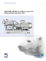 Sabroe SMC/TSMC 100 Mk 4 LL and Mk 5 Operating instructions
-
Ferroli RFA Operating instructions
-
-
Johnson Controls YORK YLHA 150 Quick Installation Manual
