Page is loading ...

Vented Gas Log Set
Models:
VWF18NA, VWF24NA,
VWF30NA
WARNINGS
If the information in this manual is not
followed exactly, a re or explosion may result
causing property damage, personal injury or
loss of life.
– Do not store or use gasoline or other
flammable vapors and liquids in the
vicinity of this or any other appliance.
– WHAT TO DO IF YOU SMELL GAS
• Do not try to light any appliance.
• Do not touch any electrical switch; do
not use any phone in your building.
• Immediately call your gas supplier from
a neighbor's phone. Follow the gas
supplier's instructions.
• If you cannot reach your gas supplier,
call the re department.
– Installation and service must be performed
by a qualied installer, service agency or
the gas supplier.
This gas log set is to be installed only in a
solid-fuel burning replace with a working ue
constructed of noncombustible material.
277300
VWF log cover
INSTALLER: Leave this manual with the appliance.
CONSUMER: Retain this manual for future refer-
ence.
Installation and Operating
Instructions
Majestic • VWF Series Installation/Owner's Manual • 27D7300 • Rev C • 10/17
►

2
VWF Series Vented Gas Log Set
Majestic • VWF Series Installation/Owner's Manual • 27D7300 • Rev C • 10/17
CONTENTS
Important Safety Information ....................................3
Product Specications ...............................................4
Logset & Burner Dimensions .................................4
Minimum Hearth Dimensions .................................4
Getting Started ............................................................5
Burner - Grate Assembly 18", 24", 30", 36" ............5
18", 24", 30", 36" Logs ...........................................5
Items for Installation ...............................................5
Minimum Free Opening Area of
Chimney Damper for Venting .................................5
Minimum chimney Height and Flue Opening .........5
Placement in a Fireplace with a Restrictive Barrier 6
Installation ...................................................................7
Damper Stop Installation ........................................7
Before Installing the Appliance ...............................7
Installation for Gas Valve Kits ...................................8
Supplemental Instructions:
SPL-NGA/SPL-LPA ................................................8
MANVK ................................................................10
MVVKLPA .............................................................10
MVVKNA ..............................................................10
CVTHL-NG ........................................................... 11
CVTHL-LP ............................................................ 11
Wiring - Millivolt ......................................................... 12
Connect the Gas .......................................................13
Log Placement ..........................................................14
Filling the Burner Pan ...........................................14
Placement of Glowing Embers (Rock Wool) ........14
Placement of Decorative Volcanic Rock ..............14
VWF18MO (Massive Oak) ...................................14
VWF24MO (Massive Oak) ...................................16
VWF30MO (Massive Oak) ...................................17
VWF18AO (American Oak) ..................................21
VWF24AO (American Oak) ..................................22
VWF30AO (American Oak) ..................................23
VWF24B (Birch) ...................................................25
VWF24/18SRO (Split River Oak) .........................26
VWF30/24SRO (Split River Oak) .........................28
VWF30SRO (Split River Oak) ..............................30
VWF18SPA (Split Pine) .......................................32
VWF24SPA (Split Pine) .......................................35
VWF30SPA (Split Pine) ........................................37
VWF24/18WP (Weathered Pine) .........................39
VWF30/24WP (Weathered Pine) .........................41
VWF30WP (Weathered Pine) ..............................43
Operating Instructions ..............................................45
SPK and CVTHL kits ..........................................45
For Your Safety Read Before Lighting ..................45
Manual Control (SPK) ..........................................45
Hi/Lo control (CVTHL) ..........................................45
Millivolt Control .................................................46
Operating Instructions for MANVK Kits ..................47
For Your Safety Read Before Lighting ..................47
Manual Control Lighting Instructions ....................47
To Turn O Gas to Heater ....................................47
Flame Appearance .....................................................48
Check Burner Flames ..........................................48
Pilot Flame Appearance .......................................48
Fireplace Draft Test ..................................................49
Remote Control Receiver Replacement .................50
Cleaning and Servicing ............................................ 50
Replacement Parts ....................................................51
Assembly ..............................................................51
Massive Oak Logs ................................................52
American Oak Logs ..............................................53
Birch Logs ............................................................53
Split River Oak Logs ............................................53
Split Pine Logs .....................................................54
Weathered Pine Logs ...........................................55
Massachusetts Requirements .................................. 58
Warranty .....................................................................59
Thank you and congratulations on your purchase of a Majestic Log Set.
PLEASE READ THE INSTALLATION AND OPERATION INSTRUCTIONS BEFORE USING THE APPLIANCE!
IMPORTANT: Read all instructions and warnings carefully before starting installation.
Failure to follow these instructions may result in a possible re hazard and will void the warranty.
►

3
VWF Series Vented Gas Log Set
Majestic • VWF Series Installation/Owner's Manual • 27D7300 • Rev C • 10/17
IMPORTANT SAFETY INFORMATION
1. The installation, combustion and ventilation air must con-
form with local codes or, in the absence of local codes,
with the National Fuel Gas Code, ANSI Z223.1.
2. Installation and repair should be done by a qualied
service person. Majestic Vented Gas Logs must be
installed only in a masonry or a UL 127 solid-fuel
replace with minimum venting requirements, see
installation section.
3. To prevent malfunction, gas log set and ue should
be cleaned at least annually by a professional service
person. More frequent cleaning may be required due
to excessive lint from carpeting, etc. It is imperative
that control compartments, burners and circulating air
passageways be kept clean.
4. A damper clamp must be installed to provide the
minimum permanent vent opening to vent ue
products, Refer to installation instructions.
5. Never burn solid fuels in a replace where a gas log
set is installed.
6. This appliance must NOT be used with glass doors
in the closed position. A replace screen must be
in place when the log set is burning. Provisions for
adequate combustion air must be provided. Adequate
combustion air usually results in all ames curling into
the replace away from screen and up the ue.
8. Keep room area clear and free from combustible
materials, gasoline and other ammable vapors and
liquids.
9. Children and adults should be alerted to the hazard
of high surface temperature and should stay away to
avoid burns or clothing ignition.
10. Young children should be carefully supervised when
they are in the same room with the gas log set in opera-
tion.
Installation of this vented gas log in the Commonwealth
of Massachusetts requires the damper be permanently
removed or welded in the full open position. In addition, a
naturally vented gas log may not be installed in a bedroom
or bathroom in the Commonwealth of Massachusetts. Flex
line installation must not exceed 36".
INSTALLER
Please leave these instructions with the appliance.
OWNER
Please retain these instructions for future reference
.
WARNING
• Any change to this heater or its controls can be dangerous.
• Improper installation or use of the heater can cause serious injury or death from
re, burns, explosion or carbon monoxide poisoning.
• Do not allow fans to blow directly into the stove. Avoid any drafts that alter burner
ame patterns.
• Do not use a blower insert, heat exchanger insert or other accessory, not approved
for use with this heater where applicable.
IMPORTANT
Read these instructions carefully before
installing or trying to operate this vent-free
gas heater.
WARNING
This product must be installed by a licensed
plumber of gas tter when installed within
the Commonwealth of Massachusetts.
11. Do not place clothing or other ammable material near
the replace when the gas logs are in use.
12. Do not use this gas log set if any part has been under-
water. Immediately call a qualied service technician
to inspect the gas logs and replace any part of the
control system and any gas control which has been
under water.
13. The gas log set
must be isolated from the gas supply
piping system by closing its individual manual shuto
valve during any pressure testing of the gas supply
piping system at test pressures equal to or less than
1/2 psig (3.5kPa).
14. Secure gas log set to replace.
15. This log set will burn o the paint on the front grate
bar. Note: See cleaning section for refurbishing.
16. LP sets must be installed with SPK-LP or
MVVKLP kits.
17. FOR MASSACHUSETTS RESIDENTS ONLY:
WARNING
This appliance is for installation only in
a solid fuel burning replace (masonry
replace or manufactured replace)

4
VWF Series Vented Gas Log Set
Majestic • VWF Series Installation/Owner's Manual • 27D7300 • Rev C • 10/17
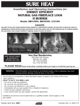
*For SPK and CVTHL Kits, add 4" to C and A
Dimensions.
For MVVK Kit, add 8" to C and A Dimensions.
For SRO and WP logs, add 8" to C and A dimensions
with or without any control valve.
The minimum inlet gas supply pressure is 4" for natural
and 10" for LP.
The maximum inlet gas supply pressure for this log set is
10" for natural and 13" for LP.
Nominal Rates (BTU/Hr)
VWF18NA 80,000 VWF30NA 90,000
VWF24NA 90,000
NOTE: Actual performance, ame height, BTU/Hr will
vary with specic installation, gas pressure, shuto
valve position (fully open), valve type, and rebox draft
conditions.
Minimum Hearth Dimensions*
SAFETY INFORMATION & PRODUCT SPECIFICATIONS
D
C
A
B
277300
VWF dims
Nous recommandons que nos
appareils de chauffage au gaz
soient installés et entretenus par
des professionnels qui ont été
accrédités aux È.U. par le National
Fireplace Institute ® (NFI) comme
étant des spécialistes du NFI en
matièred’appareils de chauffage
au gaz.
WARNING
Never connect unit to private (non-
utility) gas wells. This gas is commonly
known as wellhead gas.
Model A B C D
VWF18NA 18" 12" 12Z\x" 16Z\x"
VWF24NA 24" 12" 14" 20"
VWF30NA 30" 11" 18" 26"
FP2725
min hearth dims
Model A B C
VWF18NA 17" 13" 20"
VWF24NA 23" 13" 26"
VWF30NA 24" 13" 32"
Figure 1 -
Logset & Burner Dimensions
►
►
Figure 2 -
Minimum Hearth Dimensions
►

5
VWF Series Vented Gas Log Set
Majestic • VWF Series Installation/Owner's Manual • 27D7300 • Rev C • 10/17
Chimney Height Flue Opening
6' 64 sq in
8' 64 sq in
10' 64 sq in
15' 51 sq in
20' 51 sq in
30' 51 sq in
GETTING STARTED
MAKE SURE YOU HAVE RECEIVED ALL PARTS
Check your packing list to verify that all listed parts have
been received. You should have the following:
BURNER - GRATE ASSEMBLY 18", 24", 30"
• Burner and Grate Weldment Assembly
• Lava Rocks (x2)
• Reducer
• Glowing Embers (Rock Wool)
• Damper Clamp
• Injector
• Installation /Operating Instructions
• Vermiculite
• 3/8" Aluminum Tube with 3/8"
• Shield Plate
• 90° Elbow, 1/2" to 3/8" tube tting
18", 24", OR 30" CERAMIC FIBER OR REFRAC-
TORY LOGS
• Individual Logs
• Installation Instructions
Carefully inspect the contents for shipping damage. If any
parts are missing or damaged, immediately inform the
dealer from whom you purchased the appliance. Do not
attempt to install any part of the appliance unless you
have all parts in good condition.
ITEMS REQUIRED FOR INSTALLATION
Ensure that the following items are available before pro-
ceeding with installation:
• External regulator (for propane/L.P.G. only)
• Shuto valve
• Pipe wrench
• Piping which complies with local codes
• Drill with masonry bit (for mounting to the oor)
• Pipe sealant approved for use with propane/L.P.G.
(Resistant to sulfur compounds)
MINIMUM FREE OPENING AREA OF CHIM-
NEY DAMPER FOR VENTING
MINIMUM CHIMNEY HEIGHT AND FLUE
OPENING
WARNING
• Handle the gas log burner assembly by
the grate only. Do not pick the unit up by
the burner.
• Gloves are recommended when handling
ceramic fiber logs to prevent skin
irritation from loose fibers. Logs are
fragile — handle with care.
WARNING
The fireplace and gas logs function as
a system. If the replace is not drafting
properly and spilling into the room (check
with a match or a smoke stick), reposition
the damper clamp until the positive draft is
obtained by opening the damper. If negative
pressure in home prevents having a positive
draft, contact your dealer for assistance.
►
►

6
VWF Series Vented Gas Log Set
Majestic • VWF Series Installation/Owner's Manual • 27D7300 • Rev C • 10/17
X
FP2726
restriction depth
PLACEMENT IN A FIREPLACE WITH A RESTRICTIVE BARRIER
IMPORTANT INFORMATION FOR THE INSTALLATION OF THIS GAS LOG
SET
The following are guidelines for placing a VWF log set with SPK, MVVK, or CVTHL kit in a replace
that has a restrictive barrier along the bottom front opening of the replace. Some examples of bar-
riers are glass/screen door frames and sunken/recessed replaces.
Glass door frames with
adjustable louvers should
have the lovers fully open
while the unit is in operation.
Height of restrictive barrier caused
by glass door frames, recessed
replaces, etc. from the base or
bottom surface of the unit. (See Table).
The log set should be placed against
or as near as possible to the rear wall
of the replace/rebox.
Depth of replace/rebox.
(Refer to Table).
Figure 3
NOTE: Noncombustible material such as refractory brick
may be used to line the oor of the replace in order to
raise the height of the gas log set in relation to a restrictive
barrier.
Height of Restriction (X) Minimum Depth of Fireplace/Firebox
No Restriction 13" - SPK (Manual Control)
13Z\x" - MVVK (Millivolt Control) and MXVK (Hi/Lo Control)
0 to 1Z\x" 15"
Greater than 1Z\x" to 3" 15"
Greater than 3" Any barrier greater than three inches (3") placed in front of the
gas log set is not recommended by the manufacturer
WARNING
Barriers such as the bottom of a glass door
frame placed in front of a gas log set can
change the air ow characteristics of the
replace which in turn can cause the unit
to overheat and malfunction. Any deviation
from the installation guidelines on this sheet
will potentially void the warranty.
CAUTION
If the replace has a restrictive barrier and
is equipped with a remote receiver, it must
be placed outside. Refert to Remote Control
Receiver Replacement page 49.

7
VWF Series Vented Gas Log Set
Majestic • VWF Series Installation/Owner's Manual • 27D7300 • Rev C • 10/17
INSTALLATION
INSTALL AND OPERATE THE APPLIANCE AS DIRECTED IN THIS
MANUAL.
DAMPER STOP INSTALLATION
A damper stop must be provided with the unit. The damper stop must be installed as shown
in Figure 4 to prevent full closure of the replace damper blade and provide a minimum ue
opening, per table on page 5.
Should the clamp not t, or provide the required permanent opening from the table, have the
damper cut to provide a minimum permanent opening or install a permanent stop.
FOR MASSACHUSETTS RESIDENTS ONLY: Instal-
lation of this vented gas log in the Commonwealth of
Massachusetts requires the damper be permanently
removed or welded in the full open position. In addi-
tion, a naturally vented gas log may not be installed
in a bedroom or bathroom in the Commonwealth of
Massachusetts.
FP2727
damper
Damper Stop
Damper
FP2727
Figure 4 -
Damper Stop Installation
In compliance with ANSI Z21.60•CGA2.26 and National Fuel Gas Code, Section 6.
BEFORE INSTALLING THE APPLIANCE
• Turn o gas supply to replace or rebox.
• Clean replace oor and chimney before installing log set. Seal any ash. Clean out doors to
protect the unit from down drafts.
ASSEMBLY PROCEDURE
1. Place grate/burner assembly into rebox with the front pan facing forward.
2. Drill two (2) 5/32" diameter holes approximately 1Z\x" deep.
3. Anchor the front pan to the oor using the
screws provided.
Proper installation of the grate is essential to
prevent any movement of the gas logs and
controls during operation.
FP2728
secure burner assy
Screws
Injector
(Natural Gas Only)
FP2728
Figure 5 -
Secure Grate/Burner Assembly into Firebox

8
VWF Series Vented Gas Log Set
Majestic • VWF Series Installation/Owner's Manual • 27D7300 • Rev C • 10/17
The Safety Pilot Kit attaches to the burner pan as shown
above.
Use soapy water when checking all ttings for leaks.
SUPPLEMENTAL INSTRUCTIONS FOR SPK-
NGA/SPK-LPA
Adjust pilot ame to cover
thermocouple
INSTALLATION FOR GAS VALVE KITS
SPK-NGA Kit Includes
Valve
Pilot (Congured for NG)
Pipe Nipple
Heat Shield
Knob Extenders
SPK-LPA Kit Includes
Valve
Pilot (Congured for LP)
Air Mixing Nut
Brass Nut
Heat Shield
Knob Extenders
WARNING
LP sets must be installed with a SPK or
MVVKLP Kit which includes the air mixing
nut and vermiculite. The natural gas orice
must be removed.
FP2729
natural valve connect
Burner Fitting
Reducer
Natural Gas
Injector
Pipe Nipple
Gas Control
Valve
FP2729
Figure 6 -
Connect Valve to Unit
(Natural Gas Only)
FP2730
LP valve connect
Burner Fitting
Brass Nut
LP Air-Mixing
Injector
Gas Control
Valve
FP2730
Figure 7 -
Connect Valve to Unit
(LP Only)

9
VWF Series Vented Gas Log Set
Majestic • VWF Series Installation/Owner's Manual • 27D7300 • Rev C • 10/17
INSTALLATION FOR GAS VALVE KITS
FP2731
Install pilot
Screw
Figure 8 -
Install Pilot
FP2731
FP2732
install heat shield
Heat Shield
Gas Control
Valve
Knob Extensions
Control Knob
FP2732
Figure 9 -
Install Heat Shield

10
VWF Series Vented Gas Log Set
Majestic • VWF Series Installation/Owner's Manual • 27D7300 • Rev C • 10/17
SUPPLEMENTAL INSTRUCTIONS FOR MANVK
MANVK Kit Includes
Valve
Knob Extenders
Control Knob
SUPPLEMENTAL INSTRUCTIONS
FOR MVVKLPA MVVKLPA Kit
Includes
Valve Assembly
Pilot
Heat Shield
Air Mixing Injector
Vermiculite
Brass Nut
SUPPLEMENTAL INSTRUCTIONS
FOR MVVKNA
INSTALLATION FOR GAS VALVE KITS
WARNING
The MANVK kit is for Natural Gas Only
FP2733
MANVK
Injector
Reducer
Valve
Knob Extenders
Control
Knob
FP2733
Figure 10 -
MANVK
FP2733
MVVKLPA
LP Air-Mixing
Injector
Brass Nut
Flex Hose
90° Cast
Iron Elbow
Burner
Fitting
Gas Control
Valve
Heat Shield
FP2734
Figure 11 -
MVVKLPA
FP2735
MVVKNA
Flex Hose
Reducer
Pipe Nipple
Gas Control
Valve
Burner
Fitting Injector
Heat Shield
90° Cast
Iron Elbow
FP2735
Figure 12 -
MVVKNA
MVVKNA Kit
Includes
Valve Assembly
Pilot
Heat Shield
Pipe Nipple

11
VWF Series Vented Gas Log Set
Majestic • VWF Series Installation/Owner's Manual • 27D7300 • Rev C • 10/17
INSTALLATION FOR GAS VALVE KITS
FP2736
CVTHL ng
SUPPLEMENTAL INSTRUCTIONS FOR CVTHL-NG
CVTHL-NG Kit Includes
Valve
Pilot for NG
Pipe Nipple
Knob Extender
Heat Shield
Self Tapping Screws
Pilot Bracket
Natural Gas
Injector Reducer
Gas
Control
Valve
Pipe Nipple
Burner Fitting
Figure 13 -
CVTHL-NG Connecting Valve to Unit
(Natural Gas only)
Heat Shield
Control Knob
FP2736
FP2737
CVTHL LP
Figure 14 - CVTHL-LP
Connecting Valve to Unit
(LP only)
CVTHL-LP Kit Includes
Valve
Pilot for LP
Brass Nut
Vermiculite
LP Air-Mixing Injector
Knob Extender
Heat Shield
Self Tapping Screws
Pilot Bracket
Gas Control
Valve
Heat Shield
Control
Knob
LP Air-Mixing
Injector
Brass Nut
FP2737

12
VWF Series Vented Gas Log Set
Majestic • VWF Series Installation/Owner's Manual • 27D7300 • Rev C • 10/17
WIRING - MILLIVOLT
The Millivolt (thermopile) is a self powered combination gas
control that does not require 110VAC to operate. See Figure
15 and installation instructions provided with optional wall
switch or remote control for wiring instructions. A maximum
length of 15 feet of 18 awg two conductor wire is to be used
for wall switch. Note switches must be suitable for Millivolt
operation. The optional wall switch and remote receiver
must be mounted outside the rebox.
CHECKING SYSTEM OPERATION
The Millivolt system and individual components may be
checked with a Millivolt meter having a 0-1000MV range.
Conduct each check shown in chart below by connection
meter test leads to terminals as indicated.
A. COMPLETE MILLIVOLT SYSTEM CHECK
("A" READING - CONTACTS CLOSED - CONTROL KNOB "ON" - MAIN BURNER
SHOULD BE COME ON)
a. If the reading is more than 100 Millivolts and the automatic valve still does not come on
— replace the control.
b. If the closed circuit reading (“A” reading) is less than 100 Millivolts, determine cause for low
reading — proceed as follows:
B. THERMOPILE OUTPUT READING CHECK
(“B” READING - CONTACTS OPEN - MAIN BURNER OFF)
a. 325 Millivolts minimum. If the minimum Millivolt reading is not obtainable, readjust pilot for
maximum Millivolt output. If Millivolt reading is still below minimum specied, replace thermo-
pile.
WARNING
Label all wires prior to disconnection when
servicing controls. Wiring errors can cause
improper and dangerous operation. Verify
proper operation after servicing
WARNING
Do not connect to 110 Volt supply
FP2738
wiring diagram
Pilot
THTP
TP
TH
Millivolt
Valve
FP2738
Figure 15 -
Wiring Diagram
Optional Wall
Switch or Remote
Receiver
WARNING
Keep wiring away from heat source and
hot surfaces.
Connect
Meter Meter
Check To Test Leads to Reading
Test Terminals Should Be
A Complete TH & TH/TP Min. 100 mV
System
B Thermopile TYP & THTP Min. 325 mV
Output

13
VWF Series Vented Gas Log Set
Majestic • VWF Series Installation/Owner's Manual • 27D7300 • Rev C • 10/17
CONNECT THE GAS
NOTICE
NOTICE: A qualied gas appliance installer
must connect the appliance to the gas
supply. Consult all local codes before instal-
lation.
CAUTION
Use new black iron pipe, steel pipe, copper tubing, or internally tinned copper tubing.
Copper or internally tinned copper tubing can only according to the National Fuel
Gas Code, section 2.6.3, providing gas meets sulde limits, and where permitted by
local codes. Gas piping system must be sized to provide minimum inlet pressure
at the maximum ow rate (BTU/Hr). Undue pressure loss will occur if the pipe is
too small.
A manual shuto valve must be installed upstream of the appliance. Union tee
and plugged 1/8" NPT pressure tapping point should be installed upstream of the
appliance. See Figure 16.
WARNING
Connecting directly to an unregulated propane/
LPG tank can cause an explosion.
FP2739
gas connection
Pipe Coupling
To Gas Log Set or
to Gas Valve Shuto
Valve
Gas Supply Inlet
Figure 16 -
Gas Connection
Pipe
IMPORTANT: Hold appliance rmly with a wrench to pre-
vent movement when connecting to inlet piping.
Always use an external regulator for all propane/LPG
gas logs only, to reduce the supply tank pressure to a
maximum of 13" w.c.
Locations that the Pressure
Tapping Point May be Installed

14
VWF Series Vented Gas Log Set
Majestic • VWF Series Installation/Owner's Manual • 27D7300 • Rev C • 10/17
LOG PLACEMENT
FILLING THE BURNER PAN
Fill the burner pan with vermiculite to the bottom of the rear log and sloped to the front edge of the
burner pan. Excess vermiculite can spill forward or to the side of the burner pan. Do not overll the
propane model. Do not cover the pilot (if SPK or MVVK is installed) with vermiculite or rock wool
(embers).
PLACEMENT OF GLOWING EMBERS (ROCK WOOL)
The Wildre ame appearance can vary due to dierences in draft and replace congurations and
ember placement. After installing rear (#1) and front logs (#2 and #3), cover the entire top surface
of the vermiculite in the burner pan with the rock wool supplied with unit. Tear the rock wool into
pieces approximately 1/2" in size (roughly the size of a nickel) and cover the burner evenly. Do
no use more rock wool than the amount supplied with the unit. To enhance the appearance of the
Wildre ame, it is recommended to form a mound of rock wool in the center of the burner, 2" to 3"
high, visible through the two front logs.
PLACEMENT OF DECORATIVE VOLCANIC ROCK
Sprinkle volcanic rock in front of front glowing embers and to both sides.
DO NOT SPRINKLE ON BURNERS, EMBER BED, PILOT OR LOGS.
IMPORTANT: Do not handle logs with your bare hands! Always wear gloves to prevent skin
irritation from ceramic bers. After handling logs, wash your hands gently with soap and
water to remove any traces of bers.
VWF18 MASSIVE OAK LOGS
1. Slide shield plate behind burner pan. Figure 17.
2. Center rear log #1 on grate bars and ush with rear of
the grate. Figure 18.
LG837
VWF18 shield plate
Shield Plate
Burner Pan
LG837
Figure 17 -
Slide Shield Plate Behind Burner Pan
LG838
VWF18MO rear log
Rear Log #1
LG838
Figure 18 -
Center Rear Log #1 on Grate Bars

15
VWF Series Vented Gas Log Set
Majestic • VWF Series Installation/Owner's Manual • 27D7300 • Rev C • 10/17
LOG PLACEMENT
3. Place front left log #2 on the front of the grate and to
the left. Figure 19
4. Place front right log #3 on the front of the grate and to
the right. Figure 19
NOTE: Allow 2" between the back log and the two
front logs.
LG839
VWF18MO front logs
Front Right
Log #3
Front Left
Log #2
LG839
Figure 19 -
Place Front Left and Right Logs on Grate
Lg840
VWF18MO middle logs
Left Side Middle
Log #4 Right Side
Middle Log
#5
LG840
Figure 20 -
Place Right and Left Side Middle Logs
LG841
VWF18MO top log
Right Top
Log #6
LG841
Figure 21 -
Place Right Top Log
5. Place left side middle log #4 as
shown. Figure 20
6. Place right side middle log (#5).
Figure 20
7. Place right top log #5
as shown. Figure 21

16
VWF Series Vented Gas Log Set
Majestic • VWF Series Installation/Owner's Manual • 27D7300 • Rev C • 10/17
LG846
VWF24MO left log
VWF24 MASSIVE OAK LOGS
1. Slide shield plate behind burner pan. Figure 22
2. Center rear log #1 on grate bars and ush with rear of
the grate. Figure 23
LOG PLACEMENT
LG830
VWF24 shield
Shield Plate
Burner Pan
LG830
Figure 22 -
Slide Shield Plate Behind Burner Pan
LG842
VWF24MO rear log
Rear Log #1
LG842
Figure 23 -
Center Rear Log on Grate Bars
LG843
VWF24MO front logs
Front Left Log #2
Front Right
Log #3
LG843
Figure 24 -
Place Front Logs
3. Place front left log #2 on the front of
the grate and to the left. Figure 24
4. Place front right log #3 on the front of
the grate and to the right. Figure 24
NOTE: Allow 2" between the back
log and the two front logs.
Left Middle
Log #4
LG846
Figure 25 -
Place Left Middle Log
5. Place left side middle log #4 as
shown. Figure 25

17
VWF Series Vented Gas Log Set
Majestic • VWF Series Installation/Owner's Manual • 27D7300 • Rev C • 10/17
LOG PLACEMENT
LG844
VWF24MO middle logs
Left Side
Middle Log #4 Right Side Middle
Log #5
LG844
Figure 26 -
Place Right Side Middle Log and Left Top Log
LG845
VWF24MO top log
Right Top Log #6
LG845
Figure 27 -
Place Right Top Log
6. Place right side middle log #5 as shown.
Figure 26
7. Place left top log #7 as shown. Figure
26
8. Place right top log #6 as shown.
Figure 27
VWF30 MASSIVE OAK LOGS
1. Slide shield plate down back of burner pan. Figure 28
LG801
shield plate
Shield Plate
Burner Pan
LG801
Figure 28 -
Slide Shield Plate Behind Burner Pan
LG847
VWF30MO rear log
Rear Log #1
LG847
Figure 29 -
Center Rear Log on Grate
2. Center rear log #1 on
grate bars and ush
with rear of the grate.
Figure 29

18
VWF Series Vented Gas Log Set
Majestic • VWF Series Installation/Owner's Manual • 27D7300 • Rev C • 10/17
LOG PLACEMENT
3. Place front left log #2 on the front of the grate
and to the left. Figure 30
4. Place front right log #3 on the front of the
grate and to the right. Figure 30
NOTE: Allow 2" between the back log and
the two front logs.
LG848
VWF30MO front logs
Front Left Log #2
Front Right Log #3
LG848
Figure 30 -
Place Front Logs
5. Place left middle log #4 as shown.
Figure 31
6. Place right middle log #5 as shown.
Figure 31
LG849
VWF30MO middle logs
Right Middle Log #5
Left Middle Log #4
LG849
Figure 31 -
Place Middle Logs
7. Place right top log #6 as shown.
Figure 32
8. Place left top log #7 as shown.
Figure 32
LG849
VWF30MO top logs
Left Top Log #7 Right Top Log
#6
LG850
Figure 32 -
Place Top Logs
LG851
VWF30MO top cross log
Top Crossover
Log #8
LG851
Figure 33 -
Place Top Crossover Log
9. Place top crossover log #8 as shown.
Figure 33

19
VWF Series Vented Gas Log Set
Majestic • VWF Series Installation/Owner's Manual • 27D7300 • Rev C • 10/17
LOG PLACEMENT
Lg852
VWF30 shield plate
Shield Plate
Burner Pan
LG852
Figure 34 -
Slide Shield Plate Behind Burner Pan
►

20
VWF Series Vented Gas Log Set
Majestic • VWF Series Installation/Owner's Manual • 27D7300 • Rev C • 10/17
LOG PLACEMENT
►
/