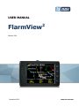
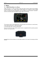
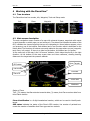
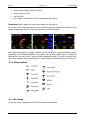
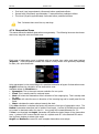
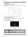
LXNAV FlarmView2 is a Flarm and ADS-B traffic and collision warning display with preloaded FlarmNet database. The 2’’ QVGA sunlight readable display has a resolution of 320*240 RGB pixels. For simple and quick manipulation, there are four push buttons on the FlarmView2. FlarmView2 monitors the vertical speed and altitude of each object on the screen. The housing is made of robust ABS plastic. On the left side of the unit there is a rocker button, on the right side there are 4 rubber push buttons. A 4 GB solid state disk is used for data storage.
LXNAV FlarmView2 is a Flarm and ADS-B traffic and collision warning display with preloaded FlarmNet database. The 2’’ QVGA sunlight readable display has a resolution of 320*240 RGB pixels. For simple and quick manipulation, there are four push buttons on the FlarmView2. FlarmView2 monitors the vertical speed and altitude of each object on the screen. The housing is made of robust ABS plastic. On the left side of the unit there is a rocker button, on the right side there are 4 rubber push buttons. A 4 GB solid state disk is used for data storage.


-
 1
1
-
 2
2
-
 3
3
-
 4
4
-
 5
5
-
 6
6
-
 7
7
-
 8
8
-
 9
9
-
 10
10
-
 11
11
-
 12
12
-
 13
13
-
 14
14
-
 15
15
-
 16
16
-
 17
17
-
 18
18
-
 19
19
-
 20
20
-
 21
21
-
 22
22
-
 23
23
-
 24
24
-
 25
25
-
 26
26
-
 27
27
-
 28
28
-
 29
29
-
 30
30
-
 31
31
-
 32
32
-
 33
33
-
 34
34


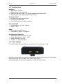
LXNAV FlarmView2 is a Flarm and ADS-B traffic and collision warning display with preloaded FlarmNet database. The 2’’ QVGA sunlight readable display has a resolution of 320*240 RGB pixels. For simple and quick manipulation, there are four push buttons on the FlarmView2. FlarmView2 monitors the vertical speed and altitude of each object on the screen. The housing is made of robust ABS plastic. On the left side of the unit there is a rocker button, on the right side there are 4 rubber push buttons. A 4 GB solid state disk is used for data storage.
Ask a question and I''ll find the answer in the document
Finding information in a document is now easier with AI
Related papers
Other documents
-
RC Electronics Flarm Indicator User manual
-
 LX FLARM Eagle User manual
-
 LX NAV V7 Owner's manual
-
Hikoki RP3608DA(L) User manual
-
 FLARM FUSION PowerFLARM Installation guide
-
 FLARM PowerFLARM Portable Installation guide
-
 Nielsen-Kellerman ClearNav User manual
-
 Brauniger IQ Motor+ Operating instructions
-
 FLARM FLARM V3+Mm User manual
-
Becker AirScout 2D on MFD6203 User manual


