GE ZDIC150WWW Installation guide
- Category
- Fridges
- Type
- Installation guide
This manual is also suitable for

i
i
stoll rio
structio
$
Automotic Icemaker
ZDIC150
ZDIS150
Design Guide
With Instollotion Instructions
monogram.corn

Installation Instructions
• BEFORE YOU BEGIN:
Read these instructions completely and carefully.
• IMPORTANT:
Save these instructions for local inspector's use.
• IMPORTANT:
Observe all governing codes and ordinances.
Note to Installer - Be sure to leave these
instructions with the Consumer.
Note to Consumer - Keep these instructions
with gour Owner's Manual for future reference.
WARNING:
This appliance must be properlg grounded.
Failure to do so can result in death, fire or
electrical shock. See "Power Supplg," page 5.
AVERTISSEMENT :
Cet appareil dolt _tre correctement
mis _ la terre. Le non-respect de ces
instructions peut causer la mort, un
incendie ou un choc _lectrique. Consulter
<<Alimentation 61ectrique >>,page 5.
If gou received a damaged icemaker, gou should
immediatelg contact gour dealer or builder,
Proper installation is the responsibilitg of the
installer. Product failure due to improper installation
is not covered under the GE Appliance Warrantg.
See the Owner's Manual for warrantg information.
• Use this appliance onlg for its intended purpose.
Check with local utilities for electrical codes that
applg in gour area. Local codes varg. Installation,
electrical connections and grounding must complg
with applicable codes. In the absence of local codes,
the icemaker should be installed in accordance with
National Electrical Code ANSI/NFPA 70-1990 or
latest edition.
For Monogram local service in gour area, call
1.800.444.1845.
For Monogram Service in Canada, call
1.800.561.3344.
For Monogram Parts and Accessories, call
1.800.626.2002.
CONTENTS
Design Information
Models Available ....................................................................]
Cutout & Product Dimensions ..........................................]
Optional Accessories ............................................................3
Tools and Materials Required ........................................3
Installation
Advance Planning ..................................................................4
Power Supply ..........................................................................5
Remove Packaging ................................................................5
Adjust Height of Icemaker ................................................5
Water Supply ..........................................................................6
Connect the Drain ..................................................................6
Connect Water Supply ........................................................7
Reverse Door Swing ........................................................7, 8
Accessories
ZIP75WW, ZIP75BB Kit for 3/4" thick panels ....9, i0
ZTBSS1 Tubular Handle Kit ............................................11

Design Information
MODELS AVAILABLE
ZDIC!50, ZDIS!50 The icemaker nag be installed below a countertop
Available in black, white and stainless steel, or used free-standing,
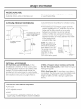
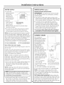
CUTOUT & PRODUCT DIMENSIONS
"16-1/2" with a 3/4" thick
custom panel
_'nI J" The installation of a 3/4" thick
'-t._\k/ custom panel will require an
L addtona 1-1/2"wdef er
strip on the hinge side.
34" rain.
Adjustable
to 34-1/2"
23-5/16" to
Cutout dimensions shown allow for a full door swing.
Additional Clearances:
• The installation of a 3//4" thick custom panel will
require an additional 1-1/2" wide filler strip on the
hinge side. The filler strip will act as a spacer
between the icemaker case and an adjacent
cabinet. The filler strip will prevent interference
with the icemaker door swing when it is installed
between frameless or framed cabinetrg. The width
of the opening must
include the filler strip.
NOTE: The addition of
a 3/4" thick front panel
will result in a front to
back depth of 24-1/16."
The product cannot be
installed flush to
adjacent 24" deep
cabinets with a
3/4" thick custom panel.
I
Factorg set ", \ -
for 110°door ",,,
swing, Allow 2" ',,
rain to wall for 1102 ",_"_,
90° door swing _t
i
5-1/2" Minimum
to Wall
OPTIONAL ACCESSORIES
ZIP75WW White and ZIP75BB Black--For the
installation of a trimless 3/4" thick custom panel
on white and black models (not for stainless steel
models). This kit provides a handle that can be
installed with the custom panel. A custom handle
of gour choice may be installed onto the 3/4" panel.
See installation instructions on pages 9 and !0.
ZTBSSl--Monogram tubular stainless steel handle
for 3/4" thick custom panels. Order this kit from gour
Monogram supplier,
ZPK1--Drain Pump Kit. For use when a floor drain is
not available. The drain pump must be installed inside
the unit and can operate at a maximum vertical
height of !0 feet. !0 feet of tubing is supplied with
the kit.
TOOLS AND MATERIALS REQUIRED
• 1//4" socket
• 3//4" adjustable wrench
• Level
GESmartConnecf" Refrigerator Tubing Kit or 1/4" O.D.
copper tubing, of sufficient length to reach the installation

Installation Instructions
ADVANCE PLANNING
CAUTION: Duetoexcessive
weight, TWO PEOPLEARE REQUIRED
TO MOVE AND INSTALLTHIS ICEMAKER.
Failure to do so can result in back or
other injurg.
MISE EN GARDE :
A cause de son poids _lev_; IL FAUT
DEU× PERSONNES POUR DEPLACER
ET INSTALLER CETTE MACHINE
GLA_ONS. Le non-respect de ces
instructions peut causer des blessures
au dos ou d'autre nature.
WATER SUPPLY
A cold water supplg with water pressure of between
30 and 120 psi is required to operate the icemaker,
If gou have questions about gour water pressure,
call a licensed, qualified plumber.
REVERSEOSMOSIS WATER SUPPLY
IMPORTANT; The performance of the icemaker
mag be affected when it is connected to a reverse
osmosis sgstem,
• The pressure of the water supplg coming out of a
reverse osmosis sgstem going to the water inlet
valve of the icemaker needs to be between 30 and
!20 psk
• If a reverse osmosis water filtration sgstem is
connected to gour cold water supplg, the water
pressure to the reverse osmosis sgstem needs to
be a minimum of/40 to 60 psi. The reverse osmosis
sgstem must provide ! gak of water per hour to
the icemaker for proper icemaker operation.
• Do not use copper tubing when the icemaker is
connected to a reverse osmosis water sgstem.
Choose the location:
Not designed for outdoor installation.
The icemaker must be installed in an area
protected from elements such as wind, rain, water
sprag or drip. The area should be ventilated with
temperatures above 55°F (!3°C) and below !!0°F
(/43°C).Best results are obtained between 70°F
(21°C)and 90°F (32°C).
• The icemaker mag be closed in on the top and
three sides as long as the front is unobstructed
for air circulation and proper operation,
-Installation should be such that the icemaker
can be moved forward for servicing, if necessarg,
-The bottom grille on the front must be
unobstructed to provide proper air flow.
ADVANCE PLANNING (cont.)
Before gou begin:
1. If a custom panel is to be installed, follow the
instructions shown on pages 9 and 10.
-Order ZIP7S (black or white) panel kit.
-Order the custom panel from the cabinet
manufacturer.
-Secure the custom panel onto the icemaker.
2. Determine a method of drainage. If a floor drain
is to be installed, the drain must be accuratelg
located. The installation of a custom door panel
will affect the drain location. See page 6 to
determine the exact location of the floor drain,
front to back, with or without a custom door
panel.
-A drain pump kit, ZPK1, is available and will not
interfere with placement of the icemaker.
3. The door swing is reversible. If desired, change
the door swing before installation.
4. Slide the icemaker into the installation location,
-Open and close the door to be sure there is no
interference.
-Check to be sure the icemaker can be moved
back into the opening, flush with adjacent
cabinetrg. There should be no interference
with the floor drain.
-Check to be sure the icemaker is level. The
icemaker will not operate properlg if it is not
level. See page 5.

Installation Instructions
POWER SUPPLY
WARNING:(Pleasereadcarefully).FOR PERSONAL SAFETY,THIS APPLIANCE
MUST BEPROPERLY GROUNDED. Failure
to follow these instructions can result
in death, fire or electrical shock.
AVERTISSEMENT:
(S'ilvous lisezavec soin). POURVOTRE
SI_CURITI_,CETAPPAREILDOlT/:TRE
CORRECTEMENTMIS/_ LA TERRE.Le
non-respect de ces instructions peut causer
la mort, un incendie OUun choc _lectrique.
Do not use an extension cord or adapter plug with
this appliance. Follow National Electrical Code or
prevailing local codes and ordinances.
This icemaker must be supplied with l15V, 60Hz,
and connected to an individual, properlg grounded
branch circuit, and protected bg a 15 or 20 amp
circuit breaker or time delag fuse.
Electrical Supply Should
Enter From Back Wall
InShaded Area.
• A properlg grounded three-prong receptacle should
be located within reach of the icemaker's 66" long
power cord. For a built-in installation, locate the
receptacle in the shaded area shown.
IMPORTANT: (Please read carefully).
The power cord of this appliance is
equipped with a three-prong _-__l_i]
(grounding) plug that mates with a
standard three-prong grounding wall
receptacle to minimize the possibilitg
of electric shock. The customer
should have the wall receptacle and circuit checked
bg a qualified electrician to make sure the receptacle
is properlg grounded and has the correct polaritg.
• Where a standard two-prong wall receptacle is
encountered, it is the personal responsibilitg and
obligation of the customer to have it replaced with
a properlg grounded three-prong wall receptacle.
Do not, under ang circumstances, cut or remove
the third (ground) prong from the power cord.
DO NOT USEAN EXTENSION CORD.
REMOVE PACKAGING AND PARTS
• Lag the cartonon rearface
and breakopen the bottom
flap.
• Set the carton upright
with all four bottom flaps
outward.
• Lift carton up and off
icemaker. Open Bottom Flaps
• Remove all tape and
packaging material from the outside and inside
of the cabinet.
ADJUST HEIGHT AND
LEVEL THE ICEHAKER
Height adjustments mag be necessarg to install
the icemaker below a countertop, and mag be
accomplished bg adjusting both the front and rear
leveling legs. The icemaker must be level to operate
properlg.
Raise Lower
To level and adjust the height:
• With one person holding the icemaker, carefullg
tilt the machine to access the leveling legs.
• Use an adjustable wrench to turn the legs.
-Turn legs right to lower, turn left to raise the
icemaker.
• Check top and side with a level. Continue
adjusting legs until the icemaker is level and
stable.

Installation Instructions
WATER SUPPLY
• A cold water
supplg is required
for icemaker
operation. The
water pressure
must be between
30 and !20 p.s.k
• Route GE
Sma rtCon nect T" Water Supply Should
Kit or !/4" O.D. Enter From Back Wall
InShaded Area.
copper tubing
between house cold water line and the water
connection locution.
• The water line should be long enough to extend
to the buck of the icemoker. Allow enough to
accommodate moving unit forward for service.
NOTE: The onlg GEapproved plastic tubing is supplied
in the GESmartConnect" Refrigerator Tubing kits. Do
not use ang other plastic water supplg line because the
line isunder pressure at all times. Other tgpes of plastic
nag crack or rupture with age and cause water
damage to gour home. GESmartConnecf" Refrigerator
Tubing Kits are available in the following lengths:
2' (0.6 m) WX08Xl0002 15' (4,6 m)WX08X10015
6' (1.8 m) WX08X10006 25' (7,6 m)WX08X]0025
Shut offthe main water supply
Turn on the nearest faucet long enough to clear the
line of water.
Install a shut-off valve between the icemaker water
valve and cold water pipe in a basement or cabinet.
The installation of an easilg accessible shut-off
valve in the water line is required.
NOTE: It is best to install the valve into a vertical
water pipe. If gou install the valve into a horizontal
water pipe, make the connection at the top or side,
rather than at the bottom, to avoid drawing off ang
sediment from the water pipe.
• Turn on the main water supplg and flush debris from
the line. Run about a quart of water through the
tubing into a bucket. Shut off water supplg at the
shut-off valve.
NOTE: Saddle tgpe shut-off valves are included in
mang water supplg kits, but are not recommended
for this application.
NOTE: Commonwealth of Massachusetts Plumbing
Codes 248CHR shall be adhered to. Saddle valves
are illegal and use isnot permitted in Hassachusetts.
Consult with gour licensed plumber.
• Install optional water filter in the water line near
the icemaker. A water filter is recommended in areas
where water supplg contains sand or particles.
Installation instructions are packed with the filter.
WATER SUPPLY (cont.)
REVERSEOSMOSIS WATER SUPPLY
IMPORTANT: The performance of the icemaker
mag be affected when it isconnected to a reverse
osmosis sgstem.
• The pressure of the water supplg coming out of a
reverse osmosis sgstem going to the water inlet valve
of the icemaker needs to be between 30 and 120 psi.
• If a reverse osmosis water filtration sgstem is
connected to gour cold water supplg, the water
pressure to the reverse osmosis sgstem needs to
be a minimum of 40 to 60 psi. The reverse osmosis
sgstem must provide i gal. of water per hour to
the icemaker for proper icemaker operation.
• Do not use copper tubing when the icemaker is
connected to a reverse osmosis water system.
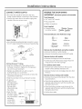
CONNECT DRAIN
1¸-
This icemaker is
equipped with a gravitg
drain to prevent water
from flowing back into
the storage bin and
overflowing onto the
floor, The ideal I ":,)
installation has a 2"
standpipe with a
to 1-1/2" PVC drain
reducer installed directlg
below the drain tube: customPanel
/Drain Hose
1" Min. Gap
-A 1" min. phgsical gap
between the bottom of
the icemaker drain hose
and the top of the house
drain is required. See
illustration.
-7-1/2" to centerlJne LocateStandpipein Exact
Centerofthe Icemaker
of the opening. _lf you haveinstalledacustompanel
-Approximatelg 3-1/2" high. andthe1-1/2"fillerstrip,positionthe
drainattheexactcenteroftheproduct.
-22" from the front, or
22-3/4" when installing a 3/4" door panel.
• Drain lines must be at least 5/8" inside diameter.
NOTE: A drain pump is necessarg when a floor
drain is not available. Order ZPK1 Drain Pump Kit
or contact gour local plumber for a recommended
pump available in gour area.
TEST DRAIN HOSEALIGNMENT: Before sliding the
icemaker into the cabinet opening, check to be sure
the bottom of the drain tube is below the rear cover.
To test, place a pan below the drain hose. Pour a
gallon of water into the ice bin and check to be sure
that water does not wet the rear cover.

Installation Instructions
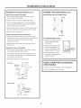
CONNECT WATER SUPPLY
• The water line should be flushed to clear ang
foreign material before connecting to the icemaken
• Connect the water line to the water supplg tube
outside of the rear access coven
Water
Supply
Line
m
m
'm
Copper Tubing:
• Use a standard plumbing female connector or union
for !/4" copper tubing that can be purchased Iocallg.
Coupling
(NotS@plied)
Lineto
Icemaker
Ferrule
(Not Supplied)
\
Nut
(Supplied)
Nut
(Supplied)
\
GE SmartConnect'" Tubing:
• Insert the molded end of the tubing into the
icemaker connection. Tighten the compression
nut until it isjust hand tight.
Tighten one additional turn with a wrench.
Overtightening can cause leaks!
Make sure there are no sharp bends or kinks that
could restrict water flow.
Slide the icemaker into its permanent location.
Water Pan
Drain_
Water Valve
5-11/16" 4-5/8"
• To prevent
rattling, be sure
the copper tubing
does not touch
the side wall or
other parts inside
the cabinet.
Open the shut-
off valve. Check
for leaks. Tighten
ang connections
(including
connections
at the valve)
if necessarg.
REVERSE THE DOOR SWING
IM PORTANT: Disconnect power to the icemaker.
Tools Required:
• 1/4" and 5/16" wrench
• Flat putts knife
• Phillips screwdriver
Parts Supplied:
• 4 hinge screws
(on some models)
®®®®
Parts Identification: (For Reference Onlg)
Hinge Pin
Handle Screw
5/16" Hex Head Endcap Screw
Hinge Screw
Remove door handle (black and white models):
• Remove the black or white handle.
• Remove the handle screws and lift off handle.
Remove the door (all models):
• Remove the hinge pin from the top hinge.
• Lift the door off of the bottom hinge. Place the
hinge pin back into the top hinge.
For stainless steel model:
• Remove two screws each from the top and
bottom of the stainless steel door skin.
• Remove the door skin and edge protectors from
the door.
Reverse the door endcaps (all models):
• Remove the screws and endcaps from the door,
top and bottom.
• Place the top endcap onto the bottom of the
opposite side of the door with the long flat side
facing the door front.
• Place the bottom endcap onto the top of the
opposite side of the door, with the long flat side
facing the door front.
• Set the door aside.

Installation Instructions
REVERSE THE DOOR SWING Icont.I
Reverse the hinges (all models}:
* Remove the screws opposite the door hinges,
top and bottom. Set aside.
* Remove the two screws holding top hinge.
* Turn the hinge upside down, with the hinge pin
pointing up. Reinstall the hinge on the opposite
side at the bottom of the door.
* Remove the bottom hinge. Turn the hinge upside
down and install on the opposite side at the top.
Remove the top hinge pin,
Prepare the stainless steel model door:
* Rotate the stainless steel door skin so that the
handle will be on the right side. Place the stainless
steel skin onto the door, keeping the edge
protectors in place.
* Reinstall the two screws in the top and bottom
of the door.
Reinstall the door (allmodels}:
* Place plastic hinge sleeve on the bottom hinge
and position the door onto the pin.
* Place plastic hinge sleeve in the top hinge hole
on the door. Align the door on the bottom hinge
and replace top hinge pin.
* Reinstall handle with original screws.
Top Hinge
Hinge Sleeve/
Door Stop
e Pin
Hex Head Hinge Screw
Bottom Hinge
>Hex Head
Hinge Screw
\Hinge Sleeve/
Door Stop
_"-Hinge Pin
REVERSE THE DOOR SWING Icont.}
Reinstall the door (all models) (cont.):
_- Top 4inge
J
f
Bottom Hinge
To reverse the door catch:
• Remove the plastic screws
from the opposite side
of the door.
• Remove the metal screws
from the magnetic door
catch and reinstall on the
opposite side of the door.
• Install the plastic screw
into place on the opposite
side of the door.
Reverse
Door Catch
Position
INSTALL NAMEPLATE ON STAINLESS
STEEL MODELS
• Remove paper backing from the nameplate.
• Place nameplate onto the doon

Installation Instructions for ZIP75WW, ZIP75BB Kit
• BEFORE YOU BEGIN:
Read these instructions completely and carefully.
• IMPORTANT:
Save these instructions for local inspector's use.
• IMPORTANT:
Observe all governing codes and ordinances.
• Note to Installer - Be sure to leave these
instructions with the Consumer.
• Note to Consumer - Keep these instructions
with gour Owner's Manual for future reference.
WARNING:
Disconnect electrical power supplg to
icemaker before installing front panel.
Do not operate icemaker while installing
panel. Failure to do so can result in death,
fire, or electrical shock.
AVERTISSEHENT :
IIfaut debrancher I'alimentation de la
machine 5 glaqons avant d'installer le
panneau avant. La machine (_glaqons
ne doit pas _tre en marche pendant
I'installation du panneau avant. Le non-
respect de ces instructions peut causer la
mort, un incendie ou un choc 61ectrique.
Kit Contents:
• 2 side trim pieces
• 8 side trim screws
• Door handle
Tools and Materials Required:
• 8 flat head wood screws, 1/2" long
• Drill and 1/8" bit
• Safetg glasses
• Tape
• Custom panel
NOTE: If installing a 3/4" trimless custom panel,
a 1-1/2" wide filler strip mag be required. The filler
strip will act as a spacer between the icemaker
case and the adjacent cabinet, and will prevent
interference with the icemaker door swing when
it is installed between frameless or framed
cabinetrg. The width of the cutout opening must
include the width of the filler strip. The product
cannot be installed flush to adjacent 24" deep
cabinets with a 3/4" thick custom panel.
This kit contains a new handle and two side
mounting brackets to support a trimless custom
door panel up to 3/4" thick. A custom handle
mag replace the supplied handle.
IMPORTANT:
• Cut edges of the custom door panel will be seen
and must be finished for best appearance. The
back side of the panel should be finished a
minimum of 1/2" on all sides.
• The custom panel, both raised and flat design,
should be constructed in the same manner
as tgpical cabinet doors.
• Order the custom panel from the cabinet manufacturer.
Be sureto provide the exact dimensions so that the
panel isconstructed accuratelg.
Custom
Panel
14_23/32"
l Handle

Installation Instructions for ZIP75WW, ZIP75BB Kit
I STEP1 DISCONNECT POWER
TO THE ICE MACHINE
STEP 2 REMOVE HANDLE
AND NAMEPLATE
• Remove the door handle bg removing the two top
mounting screws. Set screws aside. Discard handle.
• The Monogram nameplate is held in place with
adhesive. Remove the nameplate.
STEP 3 MARK MOUNTING
SCREW LOCATIONS
• Align and hold the side trim pieces against the
icemaker door and mark screw locations on the sides.
• Drill 1/8" pilot holes into the door sides of the
icemaken
STEP4 SECURE CUSTOM HANDLE
TO CUSTOM PANEL.
(SKIP THIS STEP IF
YOU ARE USING THE
SUPPLIED HANDLE)
A custom handle can be installed onto the 3//4"
thick panel, replacing the supplied handle.
• The custom handle can be installed at the top
or side of the panel.
• Drill pilot holes through the front of the custom
panel to match the chosen handle.
• Secure the handle to the panel with flat head
wood screws.
• Replace original handle screws in the top of
the door frame.
STEP 5 SECURE SIDE TRIM PIECES
TO CUSTOM PANEL
• Lag the custom panel appearance-side-down
on a clean surface.
• Align top and bottom side trim to the custom
panel sides,
• Tope the side trim pieces to the back of the
custom panel.
• Place the panel with trim against the door to be
sure that trim and panel fits the door side to side
and top to bottom, Adjust as needed.
• Mark screw locations and remove trim.
Drill pilot holes.
• Install side trim to the back side of the custom
panel with screws (not supplied). Use flat head
wood screws approximatelg 1/2" long.
STEP 6 INSTALL ASSEMBLED PANEL
ONTO THE ICE MACHINE
• Install panel to icemaker with supplied screws,
four on each side.
STEP 7 INSTALL SUPPLIED DOOR
HANDLE (IF USED)
• Install the new supplied handle with original screws.
10

ZTBSSI Monogram Tubular Handle Kit
• BEFORE YOU BEGIN:
Read these instructions completely and carefully.
• IMPORTANT:
Save these instructions for local inspector's use.
• IMPORTANT:
Observe all governing codes and ordinances.
• Note to Installer - Be sure to leave these
instructions with the Consumer.
• Note to Consumer - Keep these instructions
with gour Owner's Manual for future reference.
This kit provides a stainless steel tubular handle
to coordinate with other Monogram appliances.
• The tubular handle must be installed onto the
3/4" thick portion of the custom wood panel
before the panel is secured to the door.
TOOLS AND MATERIALS REQUIRED:
• Gloves to protect against sharp edges
• #2 Phillips screwdriver
• Drill and 1/4" bit and !/2" spade bit
• Safetg glasses
• Center punch
• Pencil
THIS KIT INCLUDES
• Tubular handle
• 2 Mounting screws
• 2 Handle standoffs
• 2 Set screws for standoffs
• 2 Nuts
• 2 Washers
• Allen Wrench
INSTALL THE TUBULAR HANDLE
• Use the handle as a template to locate and mark
the exact position of the screw holes. Be careful to
avoid interference with custom panel mounting
screws.
• Draw a pencil line, top to bottom and 7/8" from the
outside edge.
• Hold the tubular handle against the appearance
side, centered on the marked line.
• Mark the screw hole locations at the center of the
handle attachment posts.
• Center punch the marked hole locations. Drill !/4"
pilot holes from the appearance side through the
entire panel thickness.
• Use a 1/2" spade bit to drill 1/4" to 5/16" deep into
the back side of the panel. Insert washer (spacer)
into the hole.
• Install screw through the handle standoff and into
the pilot hole.
• Fasten nut onto the screw until the standoff is tight
against the panel. The screw hole on the standoff
should be pointing down toward the floor.
• Place handle attachment posts inside the standoffs.
• Use the Allen wrench to install the set screws.
Tighten handle to standoffs.
1_7/8"
" iiii
24-7/32"
i_i_i_i_i_i_i_i_i_i_i_i_i_i_i_i_i_i_i_i_i_i_i_i_i_i_i_i_i_i_i_i_i_i_i_i_i_i_i_i_i_i_i_i_i_i_i_i_i_i_i_i_i_i_i_i_i_i_ill:
i!!!!!!!!!!!!!!!!!!!!!!!!!!!!!!!!!!!!!!!!!!!!!!!!!!!!!!!!!!!!!iil
__________________________________________________________________________________________________________________________________
Custom
,Framed
Panel --
Handle
Standoff
Screw
30"
/Tubular
Handle
Handle
Attachment
Post
Set
Screw
11

NOTE: While performing installations described in this book,
safetg glasses or goggles should be worn.
For Monogram ®local service in your area, call
1.800.444.1848.
NOTE: Product improvement is a continuing endeavor
at General Electric. Therefore, materials, appearance
and specifications are subject to change without notice.
Pub.No.31-46199-1 ]
]
PartNo.224D1889P001
W10136140A 07-07 JR
Printed in the United States
GE Consumer & Industrial
Appliances
General Electric Compan 9
Louisville, KY 40225
ge.com
-
 1
1
-
 2
2
-
 3
3
-
 4
4
-
 5
5
-
 6
6
-
 7
7
-
 8
8
-
 9
9
-
 10
10
-
 11
11
-
 12
12


GE ZDIC150WWW Installation guide
- Category
- Fridges
- Type
- Installation guide
- This manual is also suitable for
Ask a question and I''ll find the answer in the document
Finding information in a document is now easier with AI
Related papers
Other documents
-
Design House 792929 Installation guide
-
 Rustica Hardware PFC-OB Installation guide
-
George Kovacs GKST1006-084 User manual
-
Everbilt 1259-110-RF Installation guide
-
Broan B6EW Installation guide
-
 GE Monogram Refrigerator refrigerator User manual
-
Sub-Zero 7025231 Installation guide
-
AOG Adapter Kit AD-5T User manual
-
Hotpoint VBSR3100DCWW Owner's manual
-
Hotpoint HTDX100GM0WW Installation guide

