Page is loading ...

1
HYDRAULIC PRESSHEADS
TETES HYDRAULIQUES DE SERTISSAGE
HYDRAULISCHE PRESSKÖPFE
CABEZAS HIDRAULICAS DE COMPRESION
TESTE OLEODINAMICHE DA COMPRESSIONE
RHU131 RHU131-C
ENGLISH
FRANÇAIS
DEUTSCH
ESPAÑOL
ITALIANO
OPERATION AND MAINTENANCE MANUAL ................................... 3
NOTICE D’UTILISATION ET ENTRETIEN ............................................. 8
BEDIENUNGSANLEITUNG ................................................................... 13
MANUAL DE USO Y MANTENIMIENTO ........................................... 18
MANUALE D’USO E MANUTENZIONE ............................................. 23
18 M 245

2
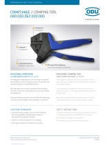
130 kN
TYPE
FORCE
MAX.
PRESSURE
10,000 psi
Made in Italy
RHU131
700 bar
123
4
WARNING LABEL - ETIQUETTES SIGNALETIQUE - HINWEISSCHILDER -
ETIQUETA DE ATENCION - ETICHETTA AVVERTENZE
This manual is the property of Cembre: any reproduction is forbidden without written permission.
Ce manuel est la proprieté de Cembre: toute reproduction est interdite sauf autorisation écrite.
Diese Bedienungsanleitung ist Eigentum der Firma Cembre.
Ohne vorherige schriftliche Genehmigung darf die Bedienungsanleitung weder vollständig noch teilweise vervielfältigt werden.
Este manual es propiedad de Cembre. Toda reproducción está prohibida sin autorización escrita.
Questo manuale è di proprietà della Cembre: ogni riproduzione é vietata se non autorizzata per scritto.
Head type
Tête type
Typ Kopf
Cabeza tipo
Tipo di testa
Year
Année
Jahr
Año
Anno
2
3
1
2
3
Force
Force
Kraft
Fuerza
Forza
Max.pressure
Max. pression
Max. Arbeitsdruck
Presión máxima
Pressione massima
4
TG0356
41
1
– Before using the tool, carefully read the instructions in this manual.
– Avant d'utiliser cet outil, lire attentivement les instructions de cette notice.
– Vor Inbetriebnahme unbedingt die Bedienungsanleitung durchlesen.
– Antes de utilizar la herramienta, leer atentamente las instrucciones contenidas en
este manual.
– Prima di utilizzare l'utensile, leggere attentamente le istruzioni contenute in questo
manuale.
2
– When operating the tool keep hands away from the danger zone.
– Au cours du sertissage, tenir les mains éloignées de la zone de danger.
– Während des Verpressens nicht mit den Händen in den Pressbereich gelangen.
– Durante su utilizacion, mantenga las manos fuera de la zona de peligro.
– Durante l'utilizzo, mantenere le mani fuori dalla zona di pericolo.
3
– Do not operate the tool when dies are not in place.
– Insérer les matrices avant d'actionner l'outil.
– Nicht ohne Presseinsatzpaar betätigen.
– No poner en presión sin matrices.
– Non mandare in pressione l'utensile senza le matrici inserite.
4

3
ENGLISH
1. GENERAL CHARACTERISTICS
Suitable for compression of electrical connectors on conductors up to 400 mm
2
(800 MCM) and
aluminium conductors up to 300 mm
2
(600 MCM).
– Crimping force: ................................................................................................................. 130 kN (14.6 sh ton)
– Max operating pressure: .............................................................................................. 700 bar (10,000 psi)
– Oil necessary (displacement): ..................................................................................... 47 cm
3
(2.9 cu. in.)
– Dimensions: length ........................................................................................................ 245 mm (9.65 in.)
width .......................................................................................................... 89 mm (3.5 in.)
– Weight: ................................................................................................................................. 3,7 kg (8.16 lbs)
2. APPLICATION RANGE
2.1) The RHU131-C head is supplied with the AU130-C adaptor, which will accept semicircular
slotted dies common to Cembre 130 kN (14.6 sh ton) tooling suitable for:
– Indentation on copper conductors.
– Circular compression on copper conductors.
– Hexagonal compression on copper, almelec or aluminium conductors.
2.2) With the upper adaptor AU130-... and lower adaptor AC130-P, the RHU131 or RHU131-C head
will accept:
– Pre-rounding dies UP130-... (used for converting aluminium sectoral conductor to a compact,
round section).
– Containing dies (MV, MVC, MVM, MUA series) and the indentors PS130-.../E
(to crimp connectors on aluminium cables using the deep indent crimping system).
3. INSTRUCTIONS FOR USE (Ref. to Fig. 2 and 3)
These instructions generally refer to the RHU131-C head, but are also suitable for the RHU131 head,
fi tted with AU130-... and AC130-P adaptors (regardless of die selected).
3.1) Setting
The head is equipped with a "self-lock" quick male coupler suitable for connection to a hydraulic,
pneumatic or electrical pump from the Cembre range.
* The RHU131-C head is the RHU131 head fi tted with adaptor AU130-C (Ref. to Fig. 2).

4
ENGLISH
3.2) Die advancement
– Insert the conductor into the connector.
– Locate the connector between the dies at the desired crimp position.
– Operate the pump until the dies touch each other.
Never pressurize the head without inserting the dies as this could cause damage to the head
and the ram.
Make sure that dies are exactly positioned on the area to be crimped; otherwise re-open
dies following instructions as per § 3.4 and re-position the connector.
3.3) Crimping
Operate the pump to advance the main ram until the dies are fully closed.
It is recommended to continue pumping until the maximum pressure valve is activated and a
“click” is heard.
3.4) Dies opening
Fully release the oil pressure from the pump, to retract the ram and release the crimped connector.
4. CRIMPING OF CONNECTORS ON COPPER CABLES (Ref. to Fig. 2 and 3)
4.1) Connector crimping
– Fit adaptor AU130-C (see § 4.2).
– Select the appropriate die set for the connector.
– Insert die set into upper and lower die holders (see § 4.3).
– Insert the conductor in the connector.
– Position the connector between the dies and ensure the correct location of the crimp.
– To crimp connector continue as § 3.2.
4.2) Adaptor assembly
Insert the AU130-C (90) adaptor in the guides on the U-fork (14) until securely located, with the
grooves on the adaptor corresponding to the locators (15) on the U-fork head (14).
Remove the adaptor by pushing it off the locators and sliding it from the head.
4.3) Dies assembly
4.3.1) Press release button (86) and insert the upper die (88) into the AU130-C adaptor (90) until
secured by the die retaining pin (87).
To remove the upper die, press the release button (86) and slide the die from the adaptor (90).
4.3.2) Press the release pin (12) and insert the lower die (89) into the seat on the ram (09) until
secured by the pin (11). To remove the die press the release pin (12) and slide the die from the ram.
To facilitate this operation an advancement of 3-4 mm (0.11 - 0.16 in.) of the ram (09) is suggested.

5
ENGLISH
5. CRIMPING OF CONNECTORS ON ALUMINIUM CABLES (Ref. to Fig. 4, and 5)
5.1) Pre-rounding conductor (for sectoral cables)
– From the table (Fig. 7, page 30) select the adaptors and pre-rounding dies for the appropriate
conductor size.
– Insert the upper adaptor AU130-... and lower adaptor AC130-P into the head (see § 5.3).
– Insert the pre-rounding die (94) into the AC130-P adaptor (see § 5.4).
– Position the conductor into the pre-rounding die (95) and locate the pre-rounding die (95) in the
adaptor AU130-... (see § 5.4). Ensure that the pre-rounding die is correctly located in the adaptor
with its upper slot in line with the internal adaptor pins.
– Operate the pump until the dies are fully closed.
Release the hydraulic pressure (see § 3.4) and remove the compacted round conductor.
5.2) Connector crimping
– Remove the pre-rounding dies and the adaptor AC130-P from the head (see § 5.4).
– From the table (Fig. 7, page 30) select the containing die and indentor recommended for the
conductor size.
– Insert the indentor PS130.../E into the ram (09) (see § 5.4).
– Insert conductor into the connector; locate the connector into the containing die; locate the
containing die in the adaptor (see § 5.4).
Commence indent crimping from the barrel end for both splices and terminals, following the
sequence shown below.
– For every operation ensure the die is correctly located in the adaptor with its upper slots in line
with the internal adaptor pins.
– Each indenting operation is completed when indentor and die are fully closed;
it is recommended to continue pumping until the maximum pressure valve is activated and a
"click" is heard (see § 3.3).
5.3) Adaptor fi tting and removal
– Insert the upper adaptor AU130-... (98) into the U-fork head (14) until secured by the locators
(15). To remove the adaptor from the U-fork head, push the adaptor from the locators and slide out.
– To insert the adaptor AC130-P(91), press the die release pin (12).
Insert the adaptor into the seat of the ram (09), until secured by the retaining pin (11).
To facilitate this operation, an advancement of 3÷4 mm (0.11 - 0.16 in.) of the ram (09) is suggested.
To remove the adaptor, press the die release pin (12) and slide the adaptor from the ram (09).
INDENTING SEQUENCE
1 2
1 4 3 2

6
ENGLISH
5.4) Dies, indentors, pre-rounding dies - fi tting and removal (Ref. to Fig. 5)
– The containing die (96) and upper pre-rounding die (95): are located in the adaptor AU130-...
(98) by grooves in the upper face.
– The lower pre-rounding die (94): is inserted or removed from the adaptor AC130-P (91), by pulling
the release button (92).
– The indentor PS130.../E (93): is inserted into the seat on the ram (09) (see § 4.3.2).
6. MAINTENANCE
The head is robust and requires very little daily maintenance.
Compliance with the following points should help to maintain the optimum performance of the tool.
6.1) Accurate cleaning
Dust, sand and dirt are a danger for any hydraulic device.
Avoid putting the head on muddy or dusty ground. Any dirt particles may score the ram and cre-
ate oil leaks.
Every day, after use, the head must be cleaned with a clean cloth, taking care to remove any residual
particles, especially around the moving parts.
6.2) Replacement of the automatic coupler
Use a 22 mm spanner to unscrew the old coupler:
– Remove the obsolete coupler.
– Carefully clean the thread to remove the old sealant.
– Apply Tefl on tape to the thread.
– Fit the new automatic coupler and tighten to 30 Nm (22 lbf ft).
The oil pressure in the head must always be completely released before disconnecting the
head from the hose.
6.3) Storage (Ref. to Fig. 1)
When not in use, the head should be stored and transported in it's case to prevent damage. Fol-
lowing cases are available:
– VAL P26 plastic case; size 445x290x115 mm (17.5x11.4x4.5 in.); weight 1,2 kg (2.65 lbs), for storage
of the head and 14 sets of semi-circular slotted dies.
– VAL 130-U steel case; size 450x305x80 mm (17.7x12x3.15 in.); weight 5 kg (11 lbs), for storage of
the head, semi-circular slotted dies and accessories for crimping aluminium connectors.
– VAL 130 steel case; size 360x280x48 mm (14.17x11x1.89 in.); weight 3 kg (6.62 lbs), for storage
of the accessories for crimping aluminium connectors.
7. RETURN TO Cembre FOR OVERHAUL
In the case of a breakdown contact our Area Agent who will advise you on the problem and give
you the necessary instructions on how to dispatch the tool to our nearest service Centre; if possible,
attach a copy of the Test Certifi cate supplied by Cembre together with the tool or fi ll in and attach
the form available in the “ASSISTANCE” section of the Cembre website.

7
The items marked ( ) are those Cembre recommend replacing if the head is disassembled.
These items are supplied on request in the “RHU131 Spare Parts Package (Cod. 6000075)”.
The guarantee is void if parts used are not Cembre original spares.
When ordering spare parts always specify the following:
- code number of item
- name of item
- type of head
- head serial number
VAL 130-U
VAL P26
VAL 130
FIG. 1 STORAGE CASES
8. PARTS LIST (Ref. to Fig. 6)
ENGLISH
Code N° Item DESCRIPTION Qty
6120123 01
CYLINDER
1
6700250
02
Ø 36 CIRCLIP
1
6170140
03
SPRING COVER
1
6360420
04
O-RING
1
6040320
05
BACK-UP RING
1
6520620
06
RAM RETURN OUTER SPRING
1
6520610
07
RAM RETURN INNER SPRING
1
6300040
08
RAM SPRING GUIDE
1
6620315
09
RAM
1
6522006
10
PIN SPRING
1
6620320
11
DIE RAM RETAINER PIN
1
6620445
12
DIE RAM RELEASE PIN
1
6760040
13
Ø 3x8 SPRING PIN
1
6280025
14
U-FORK HEAD
1
Code N° Item DESCRIPTION Qty
6340630
15
M10 DOWEL
2
6180800
16
M10 NUT
2
6100035 17
KEY
1
6900250 18
M5x14 SCREW
1
6362035
19
SEAL
1
6340082 20
M6x8 GRUB SCREW
1
6060120 21
COUPLER Q14-MS
1
6760040
22
Ø 3x8 SPRING PIN
1
6232006 23
LABEL (TG. 0356)
1
6232061 24
METAL LABEL (TG. 0261)
1
6650118 25
Ø 2,5x3,5 RIVET
2
6800186 26
PROTECTION CAP
1
6620316
COMPLETE RAM
6280026
COMPLETE FORK

12
Les éléments accompagnés d'un () sont ceux que Cembre recommande de remplacer en cas de démontage
de la tête.
Ces éléments sont fournis sur demande dans le “Paquet Rechange pour RHU131 (Cod. 6000075)”.
La garantie perd tout eff et en cas d’emploi de pièces détachées diff érentes des pièces d’origine Cembre.
Lors de la commande de pièces détachées, veuillez indiquer toujours les éléments suivants:
- numéro de code article de la pièce
- désignation de la pièce
- type de la tête
- numéro de série de la tête
FIG. 1 RANGEMENT
VAL 130-U
VAL P26
VAL 130
V
AL
P
2
6
8. PIECES DETACHEES (Voir Fig. 6)
FRANÇAIS
N° Code Pièce DENOMINATION Q.té
6120123 01
CYLINDRE
1
6700250
02
ANNEAU ELASTIQUE Ø 36
1
6170140
03
COUPELLE
1
6360420
04
JOINT TORIQUE
1
6040320
05
ANNEAU TEFLON
1
6520620
06
RESSORT EXTER RAPPEL PISTON
1
6520610
07
RESSORT INTER. RAPPEL PISTON
1
6300040
08
COUSSINET
1
6620315
09
PISTON
1
6522006
10
RESSORT
1
6620320
11
AXE DE VERROUILLAGE MATR./PISTON
1
6620445
12
AXE DE DEBLOQ MATR./PISTON
1
6760040
13
FICHE Ø 3x8
1
6280025
14
CHAPE EN “U”
1
N° Code Pièce DENOMINATION Q.té
6340630
15
VIS SANS TETE M 10
2
6180800
16
ECROU M10
2
6100035 17
CLAVETTE
1
6900250 18
VIS M5x14
1
6362035
19
JOINT
1
6340082 20
VIS SANS TETE M6x8
1
6060120 21
RACCORD Q14-MS
1
6760040
22
FICHE Ø 3x8
1
6232006 23
ETIQUETTE (TG. 0356)
1
6232061 24
PLAQUETTE (TG. 0261)
1
6650118 25
RIVET Ø 2,5x3,5
2
6800186 26
BOUCHON DE PROTECTION
1
6620316
PISTON COMPLET
6280026
CHAPE “U” COMPLETE

22
VAL 130-U
VAL P26
VAL 130
FIG. 1 ALMACENAMIENTO
8. LISTA DE COMPONENTES (Ref. a Fig. 6)
N° Código
Elemento
DESCRIPCION
C.dad
6120123 01
CILINDRO
1
6700250
02
ANILLA ELASTICA Ø 36
1
6170140
03
TAPA MUELLE
1
6360420
04
JUNTA DE GOMA
1
6040320
05
ANILLA DE PLASTICO
1
6520620
06
MUELLE EXT.RETORNO PISTON
1
6520610
07
MUELLE INT. RETORNO PISTON
1
6300040
08
SOPORTE PISTON
1
6620315
09
PISTON
1
6522006
10
MUELLE PISTON
1
6620320
11
PERNO BLOQUEO MATRIZ/PISTON
1
6620445
12
PERNO DESBLOQ. MATRIZ/PISTON
1
6760040
13
ENCHUFE Ø 3x8
1
6280025
14
HORQUILLA
1
N° Code Pièce DENOMINATION Q.té
6340630
15
TORNILLO M10
2
6180800
16
TUERCA M10
2
6100035 17
TOPE
1
6900250 18
TORNILLO M5x14
1
6362035
19
JUNTA DE GOMA
1
6340082 20
TORNILLO M6x8
1
6060120 21
ACOPLAMIENTO Q14-MS
1
6760040
22
ENCHUFE Ø 3x8
1
6232006 23
ETIQUETA (TG. 0356)
1
6232061 24
TARJETA (TG. 0261)
1
6650118 25
PASADOR Ø 2,5x3,5
2
6800186 26
TAPON DE PROTECCIÓN
1
6620316
PISTON COMPLETO
6280026
HORQUILLA COMPLETA
Los elementos indicados con ( ) son aquellos que Cembre aconseja cambiar en el caso de un posible des-
montaje de la cabeza.
Estos elementos se suministran bajo pedido en el “Paquete de Repuesto para RHU131 (Cod. 6000075) “.
La garantía pierde efi cacia si se utilizan piezas de repuesto distintas de las originales Cembre.
Al pedir piezas de repuesto, indicar siempre los elementos siguientes:
- número de código del elemento
- descripción del elemento
- tipo de cabeza
- número de serie de la cabeza
ESPAÑOL

27
ITALIANO
I particolari indicati con ( ) sono quelli che la
Cembre
consiglia di cambiare sempre nel caso di un eventuale
smontaggio della testa.
Detti particolari sono fornibili su richiesta nella “Confezione Ricambio per RHU131 (Cod. 6000075)“.
La garanzia decade qualora vengano utilizzate parti di ricambio non originali
Cembre
.
Per ordinare parti di ricambio, specifi care sempre i seguenti punti:
- numero di codice del componente
- denominazione del componente
- tipo della testa
- numero di matricola della testa
FIG. 1 CUSTODIE
VAL 130-U
VAL P26
VAL 130
8. LISTA DEI COMPONENTI (Rif. a Fig. 6)
N° Codice
Part. DENOMINAZIONE Q.tà
6120123 01
CILINDRO
1
6700250
02
ANELLO ELASTICO Ø 36
1
6170140
03
COPERCHIO MOLLA
1
6360420
04
GUARNIZIONE OR
1
6040320
05
ANELLO BK
1
6520620
06
MOLLA ESTERNA RICH. PIST.
1
6520610
07
MOLLA INTERNA RICH. PIST.
1
6300040
08
FUNGO
1
6620315
09
PISTONE
1
6522006
10
MOLLA PISTONCINO
1
6620320
11
PIST.FERMA MATRICE PIST.
1
6620445
12
PIST.SBLOCCA MATRICE PIST.
1
6760040
13
SPINA ELASTICA Ø 3x8
1
6280025
14
FORCELLA
1
N° Codice
Part. DENOMINAZIONE Q.tà
6340630
15
GRANO CON SFERA M10
2
6180800
16
DADO M10
2
6100035 17
CHIAVETTA
1
6900250 18
VITE M5x14
1
6362035
19
GUARNIZIONE PIENA
1
6340082 20
GRANO M6x8
1
6060120 21
INNESTO Q14-MS COMPLETO
1
6760040
22
SPINA ELASTICA Ø 3x8
1
6232006 23
ETICHETTA (TG. 0356)
1
6232061 24
TARGHETTA (TG. 0261)
1
6650118 25
RIVETTO Ø 2,5x3,5
2
6800186 26
TAPPO DI PROTEZIONE
1
6620316
PISTONE MONTATO
6280026
FORCELLA MONTATA

28
Hexagonal
dies
Sechskant
Presseinsätze
Matrices
hexagonales
Matrici
esagonali
Circular
dies
Rundpress-
einsätze
Matrices
semicirculares
Matrici
semicircolari
Nest and
Indent
dies
Matrize
und Stempel
Matriz y
punzón
Matrice
e punzone
Adapter
AU 130-C
Adattatore
AU 130-C
Adaptador
AU 130-C
AU 130-C
Adaptor
Adaptateur
AU 130-C
Matrice
et Poinçon
Matrices
circulaires
Matrices
hexagonales
12
88
90
86
87
14
15
11
09
89
FIG. 2
ACCESSORIES
ACCESSOIRES
ZUBEHÖR
ACCESORIOS
ACCESSORI
~ 3 - 4 mm (0.11 - 0.16 in.)
FIG. 3
DIE INSERTION
INSERTION DES MATRICES
EINSETZEN PRESSEINSÄTZE
INSERCION DE LAS MATRICES
INSERIMENTO MATRICI

31
FIG. 7 GUIDE TO THE SELECTION OF ACCESSORIES - GUIDE POUR LA SELECTION DES ACCESSOIRES -
ZUBEHÖR FÜR DIE TIEFNUTKERBUNG - GUIA PARA LA ELECCIÓN DE ACCESORIOS -
GUIDA PER LA SCELTA DEGLI ACCESSORI
*
Outside diameter of connector = 34mm
Diametre exterieur connecteur = 34mm
Verbinder Aussendurchmesser = 34mm
Diametro externo conector = 34mm
Diametro esterno connettore = 34mm
U
P 130-25
UP
130-35
UP
130-50
UP
130-70
U
P 130-95
U
P
130-120
U
P
130-150
U
P
130-18
5
U
P
130-240
U
P1
30
-
300
1
0 - 1
6
25
35
5
0
7
0
9
5
1
20
1
50
1
85
24
0
300
AC
130-
P
AU
130-15
0
A
U
1
30
-24
0
MV
35
C
O
NNE
C
T
O
RS -
C
ONNE
C
T
EURS - VERBINDER -
C
ONE
C
T
O
RES - CONN
E
TTOR
I
C
AA..-M
MT
A..-
T
T
C
C
o
n
du
c
t
o
r secti
on
S
ecti
o
n
c
o
n
du
c
t
eur
L
eiter
Q
uerschnit
t
Sec
c
i
ó
n c
able
Sezione c
a
v
o
Upper adaptor
A
d
a
p
tateur su
p
erieur
We
rk
z
e
u
g
halte
r
A
d
a
p
ta
d
or su
p
erior
A
d
a
ttatore su
p
erior
e
Lo
w
e
r adapto
r
A
daptateur inf
e
r
i
e
u
r
f
f
Ha
lter
A
daptador inf
e
r
io
r
f
f
A
d
a
ttatore inf
erior
f
f
e
Pr
e
-
r
o
un
d
ing
d
i
e
Ma
t
r
. de mise au rond
r
r
Ru
n
dd
r
ü
c
k
eins
ä
tz
e
P
r
e
re
do
n
d
e
ado
r
P
r
e
arrotondator
e
I
n
d
e
n
to
r
P
oi
nço
n
Stem
p
e
l
P
u
nz
ón
P
u
nzone
L
o
ng -
L
o
ngue - Lang - Larga -Lung
a
U
nivers
al
-
U
ni
v
e
r
selles
-
U
ni
v
ersa
l
-
Uni
v
ersale - Uni
v
ersal
e
Co
n
taining die - Matrice coquille -
Pr
e
sseins
a
tzsch
a
le -
Ma
tr
i
c
e
de su
j
ección - Matrice di conteniment
o
S
h
o
r
t
-
C
our
te
-
K
urz -
Co
r
t
a -
Co
r
t
a
P
S 130-95
/
E
PS
130-150
/
E
MU
A 300-34
A
luminiu
m
Al
uminio
A
ll
u
mini
o
MV
240
*
P
S 130-240
/
E
MT
MA
..
.
MT
A...
TT
AA
...
M
M
VM 24
0
MVC 240
M
U
A 24
0
MV
15
0
MVM 150
MV
C
150
M
U
A 15
0
MV
95
MVM
95
MVC 9
5
MU
A 9
5
P
S 130-35
/
E
MVM
35
MU
A
35
(
m
m
2
)

32
3
2
Cembre Ltd.
Dunton Park
Kingsbury Road, Curdworth - Sutton Coldfield
West Midlands B76 9EB (UK)
Tel.: +44 01675 470440 - Fax: +44 01675 470220
E-mail: [email protected]
www.cembre.co.uk
Cembre S.p.A.
Via Serenissima, 9
25135 Brescia (Italia)
Telefono: +39 030 36921
Telefax: +39 030 3365766
E-mail: [email protected]
www.cembre.com
Cembre S.a.r.l.
22 Avenue Ferdinand de Lesseps
91420 Morangis (France)
Tél.: +33 01 60 49 11 90 - Fax: +33 01 60 49 29 10
CS 92014 - 91423 Morangis Cédex
E-mail: [email protected]
www.cembre.fr
Cembre España S.L.U.
Calle Verano 6 y 8
28850 Torrejón de Ardoz
Madrid (España)
Tel.: +34 91 4852580 - Fax: +34 91 4852581
E-mail: [email protected]
www.cembre.es
Cembre GmbH
Heidemannstraße 166
80939 München (Deutschland)
Telefon: +49 89 3580676
E-mail: [email protected]
www.cembre.de
Cembre Inc.
Raritan Center Business Park
181 Fieldcrest Avenue
Edison, New Jersey 08837 (USA)
Tel.: +1 732 225-7415 - Fax: +1 732 225-7414
E-mail: [email protected]
www.cembreinc.com
www.cembre.com
IKUMA GmbH & Co. KG
Boschstraße 7
71384 Weinstadt (Deutschland)
Telefon: +49 7151 20536-60
Telefax: +49 7151 20536-80
E-mail: [email protected]
www.ikuma.de
cod. 6261037
/