Page is loading ...

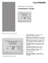
RTH2300/RTH221
Programmable Thermostat
Quick Installation Guide
69-2448ES-03

69-2448ES—03 ii
Quick Installation Guide
Identify System Type
This thermostat is compatible with the following systems:
Gas, oil or electric furnace•
Central air conditioner•
Hot water system with or without pump•
Millivolt system•
Central heating and cooling system•
Heat pump without auxiliary/backup heat•
Do you need assistance?
We are here to help.
Call 1-800-468-1502.
This thermostat cannot be used on heat pumps with
auxiliary/backup heat or on multistage systems.

1 69-2448ES—03
RTH2300/RTH221
1
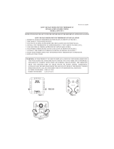
Turn Off Power to Heating/
Cooling System
M28097

69-2448ES—03 2
Quick Installation Guide
Remove Old Thermostat
2
M28099
Old thermostat
Cover
Remove old thermostat but leave wallplate with
wires attached.
Do not remove
wallplate yet
MERCURY NOTICE
Do not put your old thermostat
in the trash if it contains
mercury in a sealed tube.
Contact your local waste
management authority for
instructions regarding recycling
and proper disposal.

3 69-2448ES—03
RTH2300/RTH221
If any wires are not attached to your old thermostat or are
attached to a terminal marked C or C1, they will not be
connected to your new thermostat. Wrap the bare metal
end of each of these wires with electrical tape, so it can-
not touch and short other wires.
Identify Wires
3
M29988
Disconnect wires and remove the old wallplate only after
all wires are labeled. Wrap the wires around a pencil to
prevent them from falling though the wall opening.
Do not use non-connected
wires.
Do not use C or C1 wires.
Identify and label each wire.
IGNORE WIRE COLORS:
Use terminal screw
designations to identify
wires.

69-2448ES—03 4
Quick Installation Guide
Mount New Wallplate
Loosen the locking screw at the bottom of the 1.
thermostat. Note that the screw is captive and cannot
be removed from the wallplate.
Separate the thermostat from the wallplate as per 2.
Figure 1.
Position the wallplate against the wall and mark hole 3.
positions with a pencil.
NOTE: Levelling is for esthetics only and will not affect
the performance of the thermostat.
Drill holes at the marked positions and insert supplied 4.
wall anchors.
Pass the wires through the large opening located at 5.
the bottom center of the wallplate as per Figure 2.
Secure the wallplate to the wall with supplied mounting 6.
screws as per Figure 3.
Connect the wires to the terminals.7.
4
Figure 1 Figure 2 Figure 3
M32154

5 69-2448ES—03
RTH2300/RTH221
Connect Wires (typical wiring)
Loosen the terminal screws using a screwdriver, insert 2.
the wires, then tighten the screws.
Push any excess wire back into the wall opening.3.
Labels don’t match?
If a wire does not match any terminal designation, see next page.
5
Match each labeled wire with the terminal having the 1.
same letter.
O/B Y RC R G W
M32155
A
REMOVE JUMPER
IF YOU HAVE BOTH
R AND RC WIRES

69-2448ES—03 6
Quick Installation Guide
Connect Wires (alternate wiring)
5
If labeled wire does not match any terminal designation, see
diagram below.
M32169A
REMOVE JUMPER BETWEEN R AND RC IF YOU HAVE
WIRES ON BOTH R AND RC.
DO NOT USE C, C1, OR X WIRE. DO NOT USE B WIRE
IF YOU ALREADY HAVE 0 WIRE. WRAP BARE END OF
WIRE WITH ELECTRICAL TAPE.
PLACE A JUMPER (PIECE OF WIRE) BETWEEN Y AND
W IF YOU ARE USING A HEAT PUMP WITHOUT
AUXILIARY/BACKUP HEAT.
1
2
3
O/B Y RC R G W
2 33 1
1
OR
C1
X
B
OR
B
H
OR
Y1
M
OR
RH
4
V
OR
F
OR
W1
H
1
OR
R

7 69-2448ES—03
RTH2300/RTH221
Set jumper JP1, on the back of the thermostat, if you
have connected a wire to the G terminal.
Set Heating Fan Control
6
HG
Leave the jumper in this factory-set position if
you have a gas or oil furnace.
HE
Place the jumper to this position if you have
an electric furnace.
Incorrect jumper setting: An incorrect setting is notice-
able in a gas or oil heating system. When heating starts,
you will initially feel cold air coming out of the vents as
the fan is running before the furnace has enough time to
heat up the air.
JP1

69-2448ES—03 8
Quick Installation Guide
Set jumper JP2, on the back of the thermostat, if you
have a heat pump.
Set Heat Pump Reversing Valve
7
O Leave the jumper in this factory-set position if
you have connected O wire to the O/B terminal.
B Place the jumper to this position if you have
connected B wire to the O/B terminal.
Incorrect jumper setting: The heat pump operation will
be reversed, i.e., it will cool in Heat mode and will heat in
Cool mode.
JP2

9 69-2448ES—03
RTH2300/RTH221
Install 2 AAA batteries 1.
on the back of the
thermostat.
Install Batteries and
Thermostat
8
Align the two brackets 2.
on the top of the
thermostat with the
corresponding slots
on the top of the
wallplate.
Push the thermostat 3.
against the wallplate.
Tighten the screw 4.
at the bottom of the
thermostat.
Turn power back on 5.
at the heating/cooling
system.
M28098

Advanced Installation
System setup ......................................................................11
Temperature display ...........................................................12
Time display format ...........................................................13
Heating cycles per hour .....................................................14
Compressor protection ......................................................15
Customer assistance .........................................................16
Limited warranty .................................................................17

RTH2300/RTH221
11 69-2448ES—03
About your new thermostat
WIRING ASSISTANCE TROUBLESHOOTING
System setup
Follow the procedure below to personalize and con-
figure the thermostat according to the heating/cooling
system.
Press and hold the 1. s and t buttons simultaneously
(for three seconds) until the display appears as
shown below.
Function number
Option number
Press the 2. s or t button to change the option.
Press the 3. s and t buttons simultaneously for one
second to advance to the next function.
When the last function is displayed, press the 4. s and
t buttons to save any changes and exit the menu.
NOTE: If you do not press any button for 60 seconds
while you are in the setup menu, the thermostat auto-
matically saves any changes made and exits the menu.
At any time you can save the changes and exit by
pressing the Run button.

Advanced Installation Guide
69-2448ES—03 12
About your new thermostat
WIRINGASSISTANCETROUBLESHOOTING
Press the s or t button to select Fahrenheit or
Celsius temperature display.
Temperature display
0 Fahrenheit temperature display (°F)
1 Celsius temperature display (°C)
When correct setting is selected, press both s and t
to display next function.

RTH2300/RTH221
13 69-2448ES—03
About your new thermostat
WIRING ASSISTANCE TROUBLESHOOTING
Press the s or t button to select 12-hour display or
24-hour display.
Time display format
0 12-hour display
1 24-hour display
When correct setting is selected, press both s and t
to display next function.
2
0

Advanced Installation Guide
69-2448ES—03 14
WIRINGASSISTANCETROUBLESHOOTING
When correct setting is selected, press both s and t
to display next function.
Heating cycles per hour
Note: Make sure system switch is in the heat position.
Press the s or t button to select your heating
system and optimize its operation:
5 12 min, Gas or oil furnace. Use this setting if you
have a standard gas or oil furnace that is less than
90% efficient.
2 30 min, Steam or gravity system. Use this setting if
you have a steam or gravity heat system.
3 20 min, Hot water or high-efficiency furnace: Use
this setting if you have a hot water system or a gas fur-
nace of greater than 90% efficiency.
4 15 min, Gas or oil furnace. Use this setting if you
have a standard gas or oil furnace that is less than
90% efficient.
6 10 min, Electric furnace: Use this setting if you have
any type of electric heating system.
3
5
2 to 6 cycles per hour

RTH2300/RTH221
15 69-2448ES—03
WIRING ASSISTANCE TROUBLESHOOTING
When correct setting is selected, press the s and t
buttons to save any changes and exit the menu.
Compressor Protection
Press the s or t button to select compressor protec-
tion:
Damage can occur if the compressor is
restarted too soon after shutdown. This fea-
ture forces the compressor to wait 5 minutes
before restarting. During the wait time, the
message Cool On or Heat On flashes on the
screen. When the safe wait time has elapsed,
the message stops flashing and the compres-
sor turns on.
1 On
0 Off
4
1

Advanced Installation Guide
69-2448ES—03 16
About your new thermostat
WIRINGASSISTANCETROUBLESHOOTING
Customer assistance
For assistance with this product, please visit
http://yourhome.honeywell.com or call Honeywell Customer
Care toll-free at 1-800-468-1502.

RTH2300/RTH221
17 69-2448ES—03
About your new thermostat
WIRING ASSISTANCE TROUBLESHOOTING
One-year limited warranty
Honeywell warrants this product, excluding battery, to be free from defects
in the workmanship or materials, under normal use and service, for a
period of one (1) year from the date of purchase by the consumer. If at any
time during the warranty period the product is determined to be defective
or malfunctions, Honeywell shall repair or replace it (at Honeywell’s option).
If the product is defective,
(i) return it, with a bill of sale or other dated proof of purchase, to the place
from which you purchased it; or
(ii) call Honeywell Customer Care at 1-800-468-1502. Customer Care
will make the determination whether the product should be returned to
the following address: Honeywell Return Goods, Dock 4 MN10-3860,
1885 Douglas Dr. N., Golden Valley, MN 55422, or whether a replacement
product can be sent to you.
This warranty does not cover removal or reinstallation costs. This warranty
shall not apply if it is shown by Honeywell that the defect or malfunction
was caused by damage which occurred while the product was in the
possession of a consumer.
Honeywell’s sole responsibility shall be to repair or replace the product
within the terms stated above. HONEYWELL SHALL NOT BE LIABLE FOR
ANY LOSS OR DAMAGE OF ANY KIND, INCLUDING ANY INCIDENTAL OR
CONSEQUENTIAL DAMAGES RESULTING, DIRECTLY OR INDIRECTLY,
FROM ANY BREACH OF ANY WARRANTY, EXPRESS OR IMPLIED, OR
ANY OTHER FAILURE OF THIS PRODUCT. Some states do not allow the
exclusion or limitation of incidental or consequential damages, so this
limitation may not apply to you.
THIS WARRANTY IS THE ONLY EXPRESS WARRANTY HONEYWELL
MAKES ON THIS PRODUCT. THE DURATION OF ANY IMPLIED
WARRANTIES, INCLUDING THE WARRANTIES OF MERCHANTABILITY
AND FITNESS FOR A PARTICULAR PURPOSE, IS HEREBY LIMITED TO
THE ONE-YEAR DURATION OF THIS WARRANTY.
Some states do not allow limitations on how long an implied warranty
lasts, so the above limitation may not apply to you. This warranty gives
youspeciclegalrights,andyoumayhaveotherrightswhichvaryfrom
state to state.
If you have any questions concerning this warranty, please write
Honeywell Customer Relations, 1985 Douglas Dr, Golden Valley, MN 55422
or call 1-800-468-1502. In Canada, write Retail Products ON15-02H,
Honeywell Limited/ Honeywell Limitée, 35 Dynamic Drive, Toronto, Ontario
M1V4Z9.

Automation and Control Solutions
Honeywell International Inc.
1985 Douglas Drive North
Golden Valley, MN 55422
Honeywell Limited-Honeywell Limitée
35 Dynamic Drive
Toronto, Ontario M1V 4Z9
http://yourhome.honeywell.com
® U.S. Registered Trademark
© 2010 Honeywell International Inc.
69-2448ES—03 M.S. Rev. 10-10
Printed in U.S.A.
MERCURY NOTICE: Do not place your old thermo-
stat in the trash if it contains mercury in a sealed
tube. Contact your local waste management
authority for instructions regarding recycling and
proper disposal.
CAUTION: To avoid possible compressor damage,
do not run air conditioner if the outside temperature
drops below 50°F (10°C).
/