1
IMPORTANT!
Please read this manual before attempting
to install your Warmup product. Complete
and submit your warranty form online at
www.warmup.com or www.warmup.ca
US:1-888-927-6333
CA:1-888-592-7687
Technical Helpline
Installation Manual for
NADCM-C Series of Heaters
The only UL-Approved Membrane
System in North America
Warmup DCM-PRO
Electric
Heating System
www.warmup.com
www.warmup.ca

2
Experience MyHeating
™
Download now for iOS and Android
Easy to use
Simple and secure
set up
Unique to Warmup:
Natural Language Programming
™
Programming that speaks your language
The world’s best-selling floor heating brand™
Over 2 million installations in more than 60 countries
SmartGeo
™
Smarter geo-fencing.
Reduce energy usage
by up to 25%

3
Contents
Quick Install Guide ...................................................................4
Components Required for Installation .....................................6
Do’s & Don’ts ............................................................................7
Step 1 - Electrical Supply ........................................................9
Step 2 - Subfloor Considerations .......................................... 12
Step 3 - Subfloor Preparation ............................................... 16
Alternate Installation - Fixing Strips ................................... 17
Step 4 - Lay DCM-PRO membrane ........................................ 19
Step 5 - Layout Planning ....................................................... 20
Step 6 - Install DCM-PRO Cable ............................................. 25
Step 7 - Select Floor Covering ............................................... 27
Waterproofing ..................................................................... 28
Step 8 - Lay the Floor Covering ............................................. 30
Step 9 - Connect the Thermostat .......................................... 32
Troubleshooting ..................................................................... 33
Performance Troubleshooting ............................................... 35
How to test the heater & floor sensor ..................................... 37
Layout Plan ............................................................................ 38
Control Card ...........................................................................39
Warranty ................................................................................. 40
Technical Specifications ........................................................ 42
WARNING
Your Warmup® Underfloor heating system has been designed so that
installation is quick and straight forward, but as with all electrical
systems, certain procedures must be strictly followed. Please
ensure that you have the correct heater(s) for the area you wish
to heat. Warmup plc, the manufacturer of the Warmup® DCM-PRO
System, accepts no liability, expressed or implied, for any loss or
consequential damage suered as a result of installations which in
any way contravene the instructions that follow.
It is important that before, during and aer installation that all
requirements are met and understood. If the instructions are
followed, you should have no problems. If you require help at any
stage, please contact our helpline.
You may also find a copy of this manual, wiring instructions and other
helpful information on our website:
www.warmup.com
www.warmup.ca

4
Quick Install Guide
Quick Install Guide - The full installation instructions in this
manual must be followed.
• Ensure the subfloor is smooth,
dry and free from dust.
• We recommend installing
Warmup insulation boards for
optimum performance.
• Install perimeter strip around
the perimeter of the room
to allow for dierential
movement between finished
floor level and walls.
• If installing DCM-PRO Peel
and Stick membrane an
appropriate smoothing or
levelling compound should be
applied to coarse surfaces.
• Cut membrane to size, peel
o backing and tack in place
pressing down once aligned.
• Lay additional sheets as above
ensuring that the pegs are
aligned.
• Test the resistance of the
heater ensuring it is within the
range set out in the Reference
Resistance Band table.
• Make electrical provision for
the heater (4
“ x 4” x 2
3
/
4
”
deep
UL/cUL certified electrical
back boxes, conduit).
• If installing DCM-PRO Fleece
membrane apply a thinset
layer to the substrate using a
¼” x ¼” square notch trowel.
• Cut the membrane to size and
press into the thinset using a
float or roller, removing any air
pockets.
• Lay additional sheets as above
ensuring that the pegs are
aligned.
1
4A
3
2
4B
5

5
Quick Install Guide
• Channel a groove in the
membrane and subfloor for
the coldtail & termination
joints, enabling them to
fit flush with the top of the
membrane. DO NOT tape over
these joints!
• Install the floor sensor
centrally between two runs of
the heater.
• Lay the tiles or levelling
compound over the system
• The heater, including its joints,
must be wholly within the
thinset or levelling compound
and not exposed.
• Use flexible grout when
grouting.
• Install the heating cable at the
chosen spacing.
• Maintain a minimum 2 peg (2
3
/
8
”) perimeter spacing.
• Test the resistance of the
heating cable aer installation
and check against the
previous value to ensure no
damage has occurred.
• Test the resistance of the
heating cable aer tiling and
check against previous values
to ensure no damage has
occurred.
6
8
10 11
7
9
• Connect your Warmup
thermostat.

6
Components Required
for Installation
Components available from Warmup
Warmup Insulation Boards
NADCM-C Cable
DCM-PRO Fleece
membrane
(Fleece backed)
DCM-PRO Peel and
Stick membrane
(Self-adhesive backing)
Additional components needed as part of your Warmup heating
installation:
UL/cUL Certified Thermostat
& Floor Sensor
Digital multi-meter required for testing the resistance of the
heater and floor sensor.
Electrical tape to secure the floor sensor.
UL/cUL certified electrical housing, back boxes and junction
boxes.
UL/cUL certified electrical conduit for housing the power leads.
Modified thinset & grout.
DCM-PRO Perimeter Strip
DCM-PRO Waterproofing Kit

7
Do’s & Don’ts
Ensure that thinset used is compatible with underfloor heating
and suitable for application with non porous materials such as
the DCM-PRO membrane.
Maintain a spacing that produces no more than 16 W/ of heat
input into the floor.
Make sure all electrical work is done by qualified persons
in accordance with local building and electrical codes, the
National Electrical Code (NEC), especially article 424, Part V
of the NEC, ANSI/NFPA 70, for the US and Canadian Electrical
Code, Part 1, for Canada.
Check the resistance of the heater before, during, and aer
installation to ensure that no damage has occurred. A tolerance
of +/- 5% is allowed.
Make sure the heater is connected to a UL/cUL certified GFCI
controller or breaker where required by code.
Plan the heating system layout and installation so that any
drilling aer tiling (e.g. for fixtures such as vanity units, tubs)
will not damage the wiring. Remember to keep a copy for future
reference.
Ensure that the heater is at least 8" from other heat sources
such as luminaires and chimneys.
Ensure that the minimum free bending radius of the heater is
not less than 1”.
Ensure the subfloor is fully cured and stable before
commencing installation of the heater.
Ensure that each tile is solidly bedded in thinset, with no gaps
or voids beneath.
Make sure that the heater, including manufactured joints
are positioned under the final floor finish and completely
embedded in thinset.
Install the floor probe for the thermostat. It should be installed
centrally between two heating element runs. Ensure that the
sensor does not touch or cross over the heater.
Ensure that you have electrical provisions to run the heating
system at 120 V AC or 240 V AC according to the system being
installed.
Check the wattage and voltage of the heater to ensure you have
the correct system for your application.
Ensure any parallel runs of cold tail and sensor wire are kept
separated by a minimum of 2” within the wall, using UL/cUL
certified conduit where required.
Make sure that the system is fully grounded following the wiring
instructions provided.
Use a separate cable for the shower area.
Indicate which circuits supply power to the heater on the circuit
breaker. Attach the product labels for each heater to the circuit
breaker, for future reference.
DO

8
Do’s & Don’ts
DON’T
Cross the cable over another run, over coldtails or the floor
sensor. This will cause overheating and will damage the cable.
Cut or shorten the heater at any time.
Install parallel runs of heating cable closer than 2" if using cable
fixing strips or 2 pegs (2 ") if using the DCM-PRO membrane.
Refer to the Layout Planning page for further guidance.
Install the heater with staples or other metal fixings that can
cause damage.
Store tiles, sharp or heavy objects on top of the heater.
Install the heater below 5°F (-15°C) ambient temperature.
Attempt to bypass the GFCI if it trips and cannot be reset during
normal operation. Consult a qualified electrician or call the
helpline for further assistance.
Install the heater under permanent fixtures or in closets.
Commence installation on a screed that has not been fully
cured.
Cover the cold lead or termination joint with tape. This may
cause air pockets resulting in the joints overheating.
Install the heater beyond the room or area in which they
originate.
Attempt to repair the heater if it is damaged. Call the technical
helpline for further instructions.
Allow the thermostat to exceed the maximum temperature for
your final floor finish. Always check the maximum temperatures
allowed with the floor covering manufacturer.
Switch on the installed heater until thinset has fully cured,
check manufacturer’s instructions.
Install the heating cable closer than 2" from the wall, partitions
and permanently fixed objects
Store the DCM-PRO Peel and Stick membrane in direct sunlight.
Prolonged exposure to UV radiation will alter the properties of
the adhesive backing, voiding the product warranty.
WARNING : “RISK OF ELECTRIC SHOCK AND FIRE”.
Damage to supply conductor insulation may occur if
conductors are routed less than 2” from this heating product.
CAUTION: a ground fault protection device must be used with
this heating device”,
“ATTENTION : ce produit doit être utilisé avec une protection
de mise à la terre”, unless exempted by the Canadian Electrical
Code, Part I.

9
Step 1 -
Electrical Supply
The installation of electrical systems presents risks of fire and
electrical shock which can result in personal injury. All electrical
connections should be carried out by a qualified electrician in
accordance with the National Electrical Code and all local Codes. For
installations in Canada, refer to relevant sections in the CEC.
The heater MUST be connected to the electrical system through a
UL/cUL certified Ground Fault Circuit Interrupter (“GFCI”). If you are
not using a thermostat with an integral GFCI, ensure that the branch
circuit supplying your heaters is GFCI protected and if possible, use
a dedicated GFCI protected circuit to supply each heated zone. This
requirement is critical to the safe operation of the heater.
For smaller areas, you may be able to utilize an existing circuit. In
most cases, however, you will need a separate dedicated circuit to
power the Warmup heating cables.
NOTE: The power leads must be protected where they leave the floor
by a suitable UL/cUL certified conduit.
NOTE: A UL/cUL certified junction box is required if more than two
heaters are being installed.
NOTE: If conducting an insulation resistance test on the supply to
the thermostat, the thermostat and heaters must be isolated or
disconnected. This is to prevent the thermostat and heater(s) from
being exposed to test voltages that exceed its specified limit.
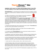
Warmup
Thermostat
Coldtail joint recessed
into the membrane
& subfloor. Coldtail
connected to the
thermostat
Termination Joint
recessed into
the membrane &
subfloor.
Coldtail installed
in UL/cUL certified
conduit.
Floor Sensor 12” into heated
area. Floor sensor connected
to thermostat

10
Step 1 -
Electrical Supply
Canadian Electrical Code, part 1 in Canada or the National Electrical Code in the USA, especially Article 424, Part V
Undertile heaters are to be installed in parallel across the load terminals of the thermostat or contactor and must
not exceed their rated load.
of the NEC ANSI/NFPA 70.
CSA/CEC or NEC
CSA/CEC or NEC
(green/bare)
(ground braid)
(yellow)
(ground braid)
(yellow)
Live (hot)
Neutral
Live (hot)
Neutral
12
12
110 -
120V
Typical Wiring Diagram 120V

11
Step 1 -
Electrical Supply
Typical Wiring Diagram 240V
Canadian Electrical Code, part 1 in Canada or the National Electrical Code in the USA, especially Article 424, Part V
of the NEC ANSI/NFPA 70.
CSA/CEC or NEC
CSA/CEC or NEC
(green/bare)
(ground braid)
(ground braid)
Live (hot)
Live (hot)
Live (hot)
Live (hot)
Undertile heaters are to be installed in parallel across the load terminals of the thermostat or contactor and must
not exceed their rated load.
NOTE: When installing the heater in kitchens or bathrooms it must be
protected by a UL/cUL certified GFCI. If the heater is switched by a separate
contactor its supply must be GFCI protected. To prevent nuisance tripping a
thermostat with integral GFCI protection should not be supplied by a GFCI
protected circuit.

12
Step 2 -
Suboor Considerations
Subfloor Preparation
Subfloors previously covered in vinyl, cork or carpeting: all old
flooring and glues must be removed. If there is bitumen as a damp
proofing layer, it must be covered with a minimum 2” of sand/cement
screed or overboarded with
3
/
8
” Warmup Insulation Boards, taking
care not to puncture the bitumen coating. The screed must be fully
cured and dry before proceeding. If using other damp proofing or
tanking systems, contact the manufacturer for advice.
For optimum performance it is recommended that you use Warmup®
Insulation Boards beneath Warmup DCM-PRO. The insulation will
improve the systems response to heating demand, saving energy and
reducing running costs.
Where expansion joints are present in the subfloor, these must be
preserved up through all covering layers, including insulation where
installed and DCM-PRO.
** The
thinset layer is only required when installing DCM-PRO Fleece membrane. / "
levelling compound is required when installing DCM-PRO Peel and Stick membrane. If the
surface the DCM-PRO Peel and Stick membrane is being applied to is smooth such that a
continuous bond can be made this layer of levelling compound is not required.
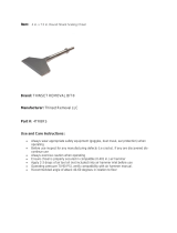
Concrete Subfloors
CONCRETE SUBFLOOR
(Recommended)
1 Floor Finish
2 ” Minimum Thinset or "
levelling compound*
3 Warmup DCM-PRO Cable
4 Warmup DCM-PRO Fleece
membrane
5 Thinset layer applied with
¼” x ¼” square notch trowel
or /" levelling compound**
6 Warmup Insulation Board
7 ” Minimum Thinset
8 Subfloor
CONCRETE SUBFLOOR
1 Floor Finish
2
1
/
4
” Minimum Thinset or /"
levelling compound*
3 Warmup DCM-PRO Cable
4 Warmup DCM-PRO Fleece
membrane
5 Thinset layer applied with
¼” x ¼” square notch trowel
or /" levelling compound**
6 Subfloor
5
1
2
3
4
6
7
8
5
6
1
2
3
4
DCM-PRO
*
1
/
4
” Minimum thinset or / " levelling compound layer is measured from the top of the
DCM-PRO membrane. The levelling compound, when used, must be applied as a single layer.
Additional layers of levelling compound must not be added.

13
** The
thinset layer is only required when installing DCM-PRO Fleece membrane. / "
levelling compound is required when installing DCM-PRO Peel and Stick membrane. If the
surface the DCM-PRO Peel and Stick membrane is being applied to is smooth such that a
continuous bond can be made this layer of levelling compound is not required.
Wood Subfloors
WOOD SUBFLOOR
(Recommended)
1 Floor Finish
2
1
/
4
” Minimum Thinset or /"
levelling compound*
3 Warmup DCM-PRO Cable
4 Warmup DCM-PRO Fleece
membrane
5 Thinset layer applied with
¼” x ¼” square notch trowel
or /" levelling compound**
6 Warmup Insulation Board
7
1
/
4
” Minimum Thinset
8 Floor Deck
9 Joists
10 Insulation
WOOD SUBFLOOR
1 Floor Finish
2
1
/
4
” Minimum Thinset or
levelling compound*
3 Warmup DCM-PRO Cable
4 Warmup DCM-PRO Fleece
membrane
5 Thinset layer applied with
¼” x ¼” square notch trowel
or /" levelling compound**
6 Floor Deck
7 Joists
8 Insulation
Step 2 -
Suboor Considerations
In addition to the general subfloor preparation instructions on
the previous page, wood subfloors should be prepared for tiling in
accordance with local tiling standards such as ANSI A108 series.
5
1
2
3
4
6
7
8
9
10
5
1
2
3
4
6
7
8
*
1
/
4
” Minimum thinset or / " levelling compound layer is measured from the top of the
DCM-PRO membrane. The levelling compound, when used, must be applied as a single layer.
Additional layers of levelling compound must not be added.

14
CONCRETE SUBFLOOR
(Recommended)
1 Floor Finish
2
3
/
8
”
Minimum Thinset or
levelling compound
3 Warmup DCM-PRO Cable
4 Warmup Fixing Strips
5 Warmup Insulation
Board
6
1
/
4
” Minimum Thinset
7 Subfloor
CONCRETE SUBFLOOR
1 Floor Finish
2
3
/
8
”
Minimum Thinset or
levelling compound
3 Warmup DCM-PRO Cable
4 Warmup Fixing Strips
5 Subfloor
5
1
2
3
4
6
7
5
1
2
3
4
Step 2 -
Suboor Considerations
Fixing Strips
Concrete Subfloors

15
Step 2 -
Suboor Considerations
1
2
3
4
7
5
6
9
8
5
6
1
2
3
4
7
WOOD SUBFLOOR
(Recommended)
1 Floor Finish
2
3
/
8
”
Minimum Thinset or
levelling compound
3 Warmup DCM-PRO Cable
4 Warmup Fixing Strips
5 Warmup Insulation
Board
6
1
/
4
” Minimum Thinset
7 Floor Deck
8 Joists
9 Insulation
WOOD SUBFLOOR
1 Floor Finish
2
3
/
8
”
Minimum Thinset or
levelling compound
3 Warmup DCM-PRO Cable
4 Warmup Fixing Strips
5 Floor Deck
6 Joists
7 Insulation
Wood Subfloors

16
Step 3 -
Suboor Preparation
• Ensure the subfloor is dry
and smooth. If necessary an
appropriate smoothing or
levelling compound should be
applied.
• If required, prime wood or
sand and cement screeded
subfloors. For proprietary
subfloors refer to the
manufacturers instructions.
• Install perimeter expansion
strips within the DCM-PRO
system, along any perimeter
or sectional expansion joints
within the subfloor to preserve
their function. Remove the
tape from the perimeter strip
to expose the adhesive back
and begin pressing it into the
wall, ensuring the strip also
touches the floor.
Installing the perimeter
strip allows for dierential
movement between the
finished floor level and walls.
IMPORTANT: When installing DCM-PRO Peel and Stick membrane
the surface the membrane is being applied to must be primed and
smooth, such that a clean and continuous bond can be made.
If necessary an appropriate /" levelling compound should be
applied. Coarse and/or loose subfloor surfaces will prevent the
membrane from forming a continuous bond. For example; cement
coated insulation boards with a raised pattern must have a levelling
compound applied over.
• Recommended Step - Install
Warmup® insulation boards
over the subfloor referring to
their installation instructions.
Warmup insulation boards
are made of extruded
polystyrene, faced on both
sides with a fibreglass mesh
embedded into a thin cement
polymer mortar. They will
help reduce the heat up times
of your system for optimal
performance.
1 2
43

17
Alternate Installation -
Installing Using Spacing Strips
When using the 12” spacing strips to secure the cable to the
subfloor, use the following provisions to ensure proper spacing of the
cable. The fixing guides included in the kit are 12” long with
1” spacing guides.
The perimeter spacing strips should be installed a minimum of 3”
away from the wall perpendicular to the planned cable runs.
(Additional stabilizing guides could be laid 40" apart across the floor).
The spacing strips can be secured to the floor using suitable
adhesive, nails, screws or strong double-sided tape.
It may be necessary to cut the guides into smaller sections to
accommodate irregular shaped rooms.
Once you have fitted the spacing strips, the heating cable may be
laid out.
Installing the heating cable
Before you start laying the underfloor heating cable, ensure that the
heating cable(s) are tested. Aer 10 feet of cable has been removed,
you will reach the point at which the unheated lead joins the heating
cable.
The factory made joint should be taped to the floor before and aer
the joint. DO NOT tape over this joint as this may create air pockets
resulting in failure of the joint. Ensure that the factory joint lays flat
on the floor. The joint must be installed under the floor covering and
covered with
3
/
8
”
thinset or self-levelling underlayment from the top of
the floor deck. A channel will need to be made into the floor deck to
accommodate the extra height of the joint. Care should be taken to
ensure that the joint is not bent. Under no circumstances should the
joint or the heated wire be installed within the conduit, only the cold
tail should occupy the UL/cUL certified conduit. Repeat this process
for each heater installed.
Install the heating cable as per the installation plan. The heating
cable should be laid in parallel lines back and forth across the main
body of the area to be heated. Use the spacing guide in the Layout
Planning page to space the cable. The standard (UL-Approved
minimum) spacing is 3 pegs (3") if using cable fixing strips or 3 pegs
(3 /") if using the DCM-PRO membrane.
Ensure that the cable is held in place by the fixing guides and that
you maintain moderate tension on the cable to prevent it from liing
during the installation of the final floor covering. Using duct tape,
secure the end of the cable to the floor. DO NOT cover the factory end
joint in tape as air pockets may cause the end joint to overheat.

18
Installing the floor sensor
The floor sensor is used for temperature regulation of the floor
surface. The end of the probe wire contains a capped sensor that
should be centred between two heating cables at least 12” into the
heated area.
The sensor wire MUST NOT touch or cross over the heating cables.
Depending on the requirements of the tiler, it may be necessary to
chisel out short channels in the subfloor to minimize the increased
height presented by the floor probe. Before chiseling the area, ensure
that the heating cable, unheated lead and floor probe are protected
to avoid damage during chiseling. Place the floor probe into the
channels and secure with fixing tape. DO NOT tape over the floor
sensor tip.
NOTE: DO NOT run the cold lead wires and the floor sensor in the
same UL/cUL certified conduit.
Alternate Installation -
Installing Using Spacing Strips
IMPORTANT - Test the cable and floor sensor
Before installing the final floor finish ensure that the cable(s) and floor
sensor is working properly using the method described on the "How
to test the heater & floor sensor" page.

19
Step 4 -
Lay DCM-PRO Membrane
• Measure and cut a length of
membrane to suit your room
using a utility knife and/or
scissors.
• If installing DCM-PRO Peel
and Stick membrane, position
the membrane and remove
the backing from one edge/
corner and stick in position
before removing the rest of
the backing.
• Mark out the floor with a
permanent marker showing
where fixtures and other
unheated areas are going to
be.
• Repeat previous steps for
subsequent runs of the
membrane, butting the runs
of membrane together tightly
until the floor area is covered,
making sure to align the pegs
between membrane runs.
• Protect the membrane with
walking boards in areas of
high foot traic and under
heavy loads.
4
3
1
• If installing DCM-PRO Fleece
membrane apply a thinset
layer to the substrate using a
¼” x ¼” square notch trowel.
• Position the membrane, fleece
side down into the thinset.
• Embed the membrane into
the thinset using a float/roller
removing any air pockets.
2A
2B

20
Step 5 -
Layout Planning
• The standard (UL-Approved
minimum) spacing is 3 pegs
(3 /") between parallel
heating cables.
• DO NOT install parallel runs of
heating cable closer than 2"
if using cable fixing strips or 2
pegs (2 ") if using the
DCM-PRO membrane.
• The heating cable must not
be cut, shortened, extended
or le in a void, it must be fully
installed within the layer of
thinset or levelling compound.
• When installing the cable
DO NOT cross the cable over
another run, over coldtails
or the floor sensor. This will
cause overheating and will
damage the cable.
NOTE: The heater should not be installed on irregular surfaces such
as stairs or up walls.
Before you begin
• Heating cables cannot be
installed across expansion
joints within the floor. Where
a heated floor is divided by
expansion joints, individual
cables should be used to
heat each area. The cold tail
may cross the expansion
joint within a 12” long UL/cUL
certified conduit if necessary.
A plan of the cable layout is required as part of the
control card so that any cutting or drilling aer tiling
will not result in injury or damage to the heater.
NOTE: Ensure the heating cable is at least 8" away from the influence
of other heat sources, such as heating and hot water pipes, lighting
fixtures or chimneys at all times.
Page is loading ...
Page is loading ...
Page is loading ...
Page is loading ...
Page is loading ...
Page is loading ...
Page is loading ...
Page is loading ...
Page is loading ...
Page is loading ...
Page is loading ...
Page is loading ...
Page is loading ...
Page is loading ...
Page is loading ...
Page is loading ...
Page is loading ...
Page is loading ...
Page is loading ...
Page is loading ...
Page is loading ...
Page is loading ...
Page is loading ...
Page is loading ...
/