Moxa PT-G503 Series Quick setup guide

Type
Quick setup guide

Moxa PT-G503 Series: Managed PRP/HSR Redundancy Boxes for Mission-Critical Industrial Automation Networks

The Moxa PT-G503 Series are managed PRP/HSR redundancy boxes designed to ensure the highest system availability and data integrity in mission-critical industrial automation networks, such as electrical substations and process automation systems. With support for PRP, HSR, and redundant protocols like Coupling and QuadBox, the PT-G503 Series delivers zero recovery time redundancy.

P/N: 1802005030013
*1802005030013*
PT-G503-PHR-PTP Series
Quick Installation Guide
Moxa Managed PRP/HSR Redundancy Box
Version 2.1, July 2020
Technical Support Contact Information
www.moxa.com/support
Moxa Americas:
Toll
-free: 1-888-669-2872
Tel:
1-714-528-6777
Fax:
1-714-528-6778
Moxa China (Shanghai office):
Toll
-free: 800-820-5036
Tel:
+86-21-5258-9955
Fax:
+86-21-5258-5505
Moxa Europe:
Tel:
+49-89-3 70 03 99-0
Fax:
+49-89-3 70 03 99-99
Moxa Asia-Pacific:
Tel:
+886-2-8919-1230
Fax:
+886-2-8919-1231
Moxa India:
Tel:
+91-80-4172-9088
Fax:
+91-80-4132-1045
2020 Moxa Inc. All rights reserved.
- 2 -
Overview
The PT-G503-PHR-PTP series redundancy boxes (RedBoxes) are
compliant with the latest standardized redundancy protocols for
industrial automation networks, IEC 62439-3 Clause 4 (Parallel
Redundancy Protocol, PRP) and IEC 62439-3 Clause 5 (High availability
Seamless Redundancy, HSR). PRP/HSR ensures the highest system
availability and data integrity for mission-critical applications in
electrical substation and/or process automation systems that require
zero recovery time redundancy. The redundant protocols Coupling and
QuadBox are also supported. The PT-G503-PHR-PTP series comes with
three 10/100/1000BaseT(X) and 100/1000BaseSFP slot combo ports.
One slot (INTERLINK port) is for an internal link for connecting with a
SAN (Singly Attached Node). The other two ports (LAN A and LAN B
ports) are for PRP/HSR redundant protocol communications. With this
full Gigabit Ethernet port design, the PT-G503-PHR-PTP series provides
high performance for PRP/HSR systems. The PT-G503-PHR-PTP series
also provides hardware-based IEEE 1588v2 PTP when in end-to-end
one-step transparent clock mode for timing-critical applications and
isolated dual power inputs with 24/48 VDC or 110/220 VDC/VAC power
supply ranges to increase the reliability of the power supply.
Package Checklist
The Moxa PT-G503-PHR-PTP series products are shipped with the
following items. If any of these items are missing or damaged, please
contact your customer service representative for assistance.
1 PT-G503-PHR-PTP redundancy box
DIN-rail kit
Protective caps for SFP ports
USB cable
Quick installation guide (printed)
Documentation and software CD
Warranty card
- 3 -
Panel Layout
1. Power input PWR1/PWR2 LED
2. State LED / Fault LED
3.
PRP/HSR/QUADBOX/COUPLING
LED
4. A/B port LED
5. Ethernet console port LED
6. INTERLINK port LED
7. 10/100/1000BaseT(X) A/B p
ort
and interlink port or
100/1000BaseSFP slot combo
ports
8. 10/100/1000BaseT(X) Et
hernet
console port
9. Model name
10.
Terminal block for power input
(PWR1, PWR2)
11.
Reset button
12.
Screw hole for grounding cable
13.
USB console port
14.
USB storage port (ABC-02-USB
-
T)
15.
Terminal block for power input
16.
Terminal block for DI and Relay
1
17.
Screw hole for wall mounting
kit
18.
DIN-rail kit
- 4 -
Mounting Dimensions (unit = mm (inch))
DIN-Rail Mounting
The metal DIN-rail kit is fixed to the back panel of the PT-G503-PHR-
PTP when you take it out of the box. Mount the PT-G503-PHR-PTP on
corrosion-free mounting rails that meet the EN 60715 standard.
- 5 -
Installation
STEP 1:
Insert the upper lip of the DIN
-rail
into the DIN
-rail mounting kit.
STEP 2
:
Press the
PT-G503-PHR-PTP
towards the DIN
-rail until it snaps
into place.
Removal
STEP 1:
Pull down the latch on the
mounting kit with a screwdriver
.
STEP 2
& 3:
Slightly pull the PT
-G503-PHR-PTP
forward and lift up to remove it
from the DIN
-rail.
Wall Mounting (optional)
For some applications, you will find it convenient to mount the PT-
G503-PHR-PTP on the wall, as shown in the following figures.
STEP 1:
Remove the aluminum DIN-rail attachment plate from the PT-G503-
PHR-PTP rear panel, and then attach the wall mount plates as shown in
the diagram below.
- 6 -
STEP 2:
Mounting the PT
-G503-PHR-PTP to a wall requires 6
screws. Use the PT
-G503-PHR-PTP, with wall mount
plates attached, as a guide to mark the correct
locations of the 6 screws. The heads of the scr
ews
should be less than 6.0 mm in diameter, and the shafts
should be less than 3.5 mm in diameter, as shown in
the figure at the right.
NOTE
Before tightening the screws into the wall, make sure the screw
head and shank size are suitable by inserting
the screw into
one of the keyhole
-shaped apertures of the wall mounting
plates.
DO NOT screw the screws in completelyleave a space of about 2 mm
to allow room for sliding the wall mount panel between the wall and the
screws.
STEP 3:
Once the screws are fixed in the wall, insert the four screw heads
through the large parts of the keyhole-shaped apertures, and then slide
the PT-G503-PHR-PTP downwards, as indicated. Tighten the four screws
for added stability.
Wiring Requirements
ATTENTION
Safety First!
Be sure to disconnect the power before installing and/or wiring
your Moxa PRP/HSR redundancy box.
Calculate the maximum possible current in each power wire and
common wire. Observe all electrical codes dictating the
maximum cur
rent allowable for each wire size. If the current
goes above the maximum ratings, the wiring could overheat,
causing serious damage to your equipment.
Be sure to read and follow these important guidelines:
Use separate paths to route wiring for power and devices. If power
wiring and device wiring paths must cross, make sure the wires are
perpendicular at the intersection point.
NOTE: Do not run signal or communications wiring and power
wiring through the same wire conduit. To avoid interference, wires
with different signal characteristics should be routed separately.
Use the type of signal transmitted through a wire to determine
which wires should be kept separate. The rule of thumb is that
wiring that shares similar electrical characteristics can be bundled
together.
Keep input wiring and output wiring separate.
When necessary, you should label the wiring to all devices in the
system.
- 7 -
Grounding the PRP/HSR Redundancy Box
Grounding and wire routing help limit the effects of noise due to
electromagnetic interference (EMI). Run the ground connection from
the ground screw to the grounding surface prior to connecting devices.
ATTENTION
This product is intended to be mounted to a well
-grounded
mounting surface, such as a metal panel.
Wiring the Dual Power Inputs
In order to support redundancy, the power system of the PT-G503-
PHR-PTP is designed to work with two independent (Separated Neutral
Lines) power sources.
Take the following steps to wire the dual power inputs:
STEP 1: Insert the neutral/line (N/L) AC or negative/positive (-/+) DC
wires into the terminals.
STEP 2: To keep the AC or DC wires from pulling loose, use a small
flat-blade screwdriver to tighten the wire-clamp screws on the front of
the terminal block connector.
STEP 3: Insert the plastic terminal block connector prongs into the
terminal block receptor, which is located on the PT’s bottom panel.
NOTE
For the HV model with AC wires, each wire from the power
supply source must be within 85 to 264 VAC RMS. To measure
and ensure the AC voltage for the PWR1 of L/+ and PWR2 of
L/+ is within the correct range, please use a qualified Digital
Multi
-meter (e.g. Fluke 85V or equivalent) before connecting
and applying the power source to the PT
-
G503 PWR1 and PWR2
input terminals.
- 8 -
NOTE
If you intend to only use one power input, be sure to disconnect
the other power input (unplug the power cord or disconnect the
power input from the L and N contacts). Only one power input
LED will be on.
ATTENTION
Before connecting the PT
-G503-PHR-
PTP to the AC or DC power
inputs, make sure the power source voltage is stable.
Wiring the Digital Inputs
The PT-G503-PHR-PTP has one digital input, DI 1. The DI consists of
two contacts from the 5-pin terminal block connector on the PT-G503-
PHR-PTP’s bottom panel. The remaining contacts are used for the PT-
G503-PHR-PTP’s Relay 1. The top view of the terminal block connector
is shown below.
Take the following steps to wire the digital input:
STEP 1: Insert the negative (ground)/positive DI wires into the /I1
terminals.
STEP 2: To keep the DI wires from pulling loose, use a small flat-blade
screwdriver to tighten the wire-clamp screws on the front of the
terminal block connector.
STEP 3: Insert the plastic terminal block connector prongs into the
terminal block receptor, which is located on the PT-G503-PHR-PTP’s
bottom panel.
Auto MDI/MDI-X Connection
The Auto MDI/MDI-X function allows users to connect the PT-G503-
PHR-PTP’s 10/100/1000BaseT(X) ports to any kind of Ethernet device,
without needing to pay attention to the type of Ethernet cable being
used for the connection. You may use either a straight-through cable or
cross-over cable to connect the PT-G503-PHR-PTP to Ethernet devices.
Communication Connections
Each PT-G503-PHR-PTP has 4 types of communication ports:
3 Gigabit Ethernet ports: 3 10/100/1000BaseTX and
3 100/1000BaseSFP ports
1 Ethernet console port
1 USB console port (type B connector)
1 USB storage port (type A connector)
- 9 -
10/100/1000BaseT(X) Ethernet Port Connection
The 10/100/1000BaseT(X) ports located on the front panel are used to
connect to Ethernet-enabled devices. Most users will choose to
configure these ports for Auto MDI/MDI-X mode, in which case the
port’s pinouts are adjusted automatically depending on the type of
Ethernet cable used (straight-through or cross-over), and the type of
device (NIC-type or HUB/Switch-type) connected to the port.
In what follows, we give pinouts for both MDI (NIC-type) ports and
MDI-X (HUB/Switch-type) ports. We also give cable wiring diagrams for
straight-through and cross-over Ethernet cables.
10/100Base T(x) RJ45 Pinouts
MDI Port Pinouts
MDI-X Port Pinouts
8-pin RJ45
Pin
Signal
1
Tx+
2
Tx-
3
Rx+
6
Rx-
Pin
Signal
1
Rx+
2
Rx-
3
Tx+
6
Tx-
1000Base T(x) RJ45 Pinouts
Pin
MDI
MDI-X
1
BI_DA+
BI_DB+
2
BI_DA-
BI_DB-
3
BI_DB+
BI_DA+
4
BI_DC+
BI_DD+
5
BI_DC-
BI_DD-
6
BI_DB-
BI_DA-
7
BI_DD+
BI_DC+
8
BI_DD-
BI_DC-
RJ45 (8-pin) to RJ45 (8-pin) Straight-Through Cable Wiring
RJ45 (8-pin) to RJ45 (8-pin) Cross-Over Cable Wiring
- 10 -
100Base-FX or 1000Base-X SFP Fiber Port
The Gigabit Ethernet ports on the PT-G503-PHR-PTP are SFP slots,
which require 100Base-FX/1000Base-X or Gigabit mini-GBIC fiber
transceivers to work properly. Moxa provides complete transceiver
models for various distance requirements.
Multi-mode:
1000BaseSX
0 to 550 m, 850 nm (50/125 μm, 400 MHz x km)
0 to 275 m, 850 nm (62.5/125 μm, 200 MHz x km)
1000BaseLX
0 to 1100 m, 1310 nm (50/125 μm, 800 MHz x km)
0 to 550 m, 1310 nm (62.5/125 μm, 500 MHz x km)
Single mode:
1000BaseLH
0 to 10 km, 1310 nm (9/125 μm, 3.5 PS/(nm x km))
1000BaseLHX
0 to 40 km, 1310 nm (9/125 μm, 3.5 PS/(nm x km))
1000BaseZX
0 to 80 km, 1550 nm (9/125 μm, 19 PS/(nm x km))
Multi-mode:
100BaseFX
0 to 5 km, 1300 nm (50/125 μm, 800 MHz x km)
0 to 4 m, 1300 nm (62.5/125 μm, 500 MHz x km)
Single mode:
100BaseFX
0 to 40 km, 1310 nm (9/125 μm, 3.5 PS/(nm x km))
The concept behind the LC port and cable is quite straightforward.
Suppose you are connecting devices I and II. Unlike electrical signals,
optical signals do not require a circuit in order to transmit data.
Consequently, one of the optical lines is used to transmit data from
device I to device II, and the other optical line is used to transmit data
from device II to device I, for full-duplex transmission.
Remember to connect the Tx (transmit) port of device I to the Rx
(receive) port of device II, and the Rx (receive) port of device I to the
Tx (transmit) port of device II. If you make your own cable, we suggest
labeling the two sides of the same line with the same letter (A-to-A and
B-to-B, as shown below, or A1-to-A2 and B1-to-B2).
USB Console Connection
The PT-G503-PHR-PTP has one USB console port (type B connector),
located on the bottom panel. Use the USB cable (provided in the
product package) to connect the PT-G503-PHR-PTP’s console port to
your PC’s USB port and install the USB driver (available in the software
CD) on the PC. You may then use a console terminal program, such as
Moxa PComm Terminal Emulator, to access the PT-G503-PHR-PTP’s
console configuration utility.
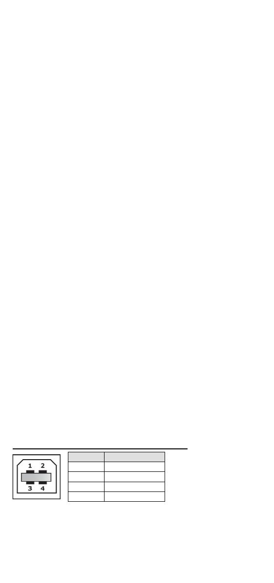
USB Console Port (Type B Connector) Pinouts
Pin
Description
1
D- (Data-)
2
VCC (+5V)
3
D+ (Data+)
4
GND (Ground)
USB Storage Connection
The PT-G503-PHR-PTP has one USB storage port (type A connector) on
the bottom panel. Use Moxa’s ABC-02-USB-T automatic backup
configurator to connect the PT-G503-PHR-PTP’s USB storage port for
configuration backup, firmware upgrade, or system log file backup.
- 11 -
ABC-02-USB Installation
Plug the ABC-02-USB into the PT-G503-PHR-PTP’s USB storage port. If
you would like to secure the ABC-02-USB to the wall, we suggest using
an M4 screw.
USB Storage Port (Type A Connector) Pinouts
Pin
Description
1
VCC (+5V)
2
D- (Data-)
3
D+ (Data+)
4
GND (Ground)
Restore Factory Defaults Button
Press and hold the Reset button for 5 seconds to load the factory
default settings. Use a pointed object, such as a straightened paper clip
or toothpick, to depress the Reset button. This will cause the STATE
LED to blink once a second. After depressing the button for 5
continuous seconds, the STATE LED will start to blink rapidly. This
indicates that factory default settings have been loaded and you can
release the reset button.
NOTE
Do NOT power off the PRP/HSR redundancy box when loading
default settings.
LED Indicators
LED
Color
State
Description
PWR 1 Amber
ON
Power is being supplied to the main
system’s power input PWR1
OFF
Power is not being supplied to the main
system’s power input PWR1
PWR 2 Amber
ON
Power is being supplied to the main
system’s power input PWR2
OFF
Power is not being supplied to the main
system’s power input PWR2
STATE
Green
ON
System has passed self-diagnosis test
on boot-up and is ready to run
Blinking
1. System is undergoing the self-
diagnosis test
2. System detects the ABC-02 USB
plugged into the USB storage port
3. Blinks once per second when
pressing the reset button for 5
seconds
4. Blinks rapidly when the reset button
has been pressed continuously for 5
seconds, indicating that the device
will be reset to factory defaults
Red ON
System failed self-diagnosis on boot-up.
RAM Test Fail / System Info. Read
Fail / Switch Initial Fail / PTP PHY
Error.
FW Checksum Fail /
Uncompress Fail
(+ Green Coupler lit on: SW FAIL)
- 12 -
LED
Color
State
Description
FAULT Red
ON
1. System has failed, or is under quick
inspection
2. The relay signal contact is open
3. ABC-02 loading/saving failure
OFF
The system is operating normally
PRP Green
ON
PRP is working
OFF
PRP is not enabled
HSR Green
ON
HSR is working
OFF
HSR is not enabled
QUADBOX Green
ON
QuadBox function is working
OFF
QuadBox function is not enabled
COUPLING
Green
ON
PRP/HSR Coupling function is working
OFF
PRP/HSR Coupling function is not
enabled
Link/Act/
Speed
(A, B,
InterLink,
Ethernet
Console)
Green
ON
When there is a secure connection (or
link) to a 1000 Mbps device on any port.
Blinking
When data is being transmitted or
received at 1000 Mbps.
Amber
ON
When there is a secure connection (or
link) to 10/100 Mbps Ethernet device on
any port.
Blinking
When data is being transmitted or
received at 10/100 Mbps.
Off
OFF
Link down or no link
Specifications
Interface
Gigabit Ethernet
3 x 10/100/1000BaseT(X) ports or
100/1000BaseSFP combo ports
Console Port Ethernet console (10/100/1000 Mbps RJ45),
USB-serial console (Type B connector)
Storage Port
USB storage (Type A connector for ABC-02-
USB)
LED Indicators
PWR 1, PWR 2, STATE, FAULT, PRP, HSR,
QUADBOX, COUPLING, 100/1000M
Alarm Contact
One relay output with current carrying capacity
of 1 A @24 VDC
Digital Inputs
One input with the same ground, but isolated
from the electronics
• +13 to +30 V for state “1”
-30 to +3 V for state “0”
• Max. input current: 8 mA
Power
Input Voltage
WV: 24/48 VDC (18 to 72 VDC)
HV: 110/220 VDC/VAC
(88 to 300 VDC and 85 to 264 VAC)
Input Current
Max. 0.660/0.360 A @ 24/48 VDC
Max. 0.150/0.080 A @ 110/220 VDC
Max. 0.260/0.170 A @ 110/220 VAC
Connection
5-pin terminal block
Overload Current
Protection
Present
- 13 -
Reverse Polarity
Protection
Present
Physical Characteristics
Housing
Aluminum alloy, IP40 protection
Dimensions
80 x 160 x 110 mm (3.15 x 6.30 x 4.33 in)
Weight
1210 g (2.69 lb)
Installation
DIN-rail mounting
Environmental Limits
Operating Temperature
-40 to 85°C (-40 to 185°F)
Storage Temperature
-40 to 85°C (-40 to 185°F)
Ambient Relative
Humidity
5 to 95% (non-condensing)
Warranty
Warranty Period
5 years
Details
See www.moxa.com/warranty
Restricted Access Locations
This equipment is intended to be used in Restricted Access
Locations, such as a computer room, with access limited to
SERVICE PERSONNEL or USERS who have been instructed on how
to handle the metal chassis of equipment that is so hot that special
protection may be needed before touching it. The location should
only be accessible with a key or through a security identity system.
External metal parts of this equipment are extremely hot!! Before
touching the equipment, you must take special precautions to
protect your hands and body from serious injury.
Power Connection Wiring
You should always connect both power supplies when using this device,
and disconnect both power supplies when this device is not in use. If
only one power supply is connected, you could receive a hazardous
electric shock by touching the unconnected terminals of the other
power supply.
All power connection wiring must be done by a qualified electrician and
follow the National Electrical Code, ANSI/NFPA 70, and Canadian
Electrical Code, Part I, CSA C22.1. An IEC certified or UL listed single-
phase type circuit-breaker, rated for a maximum of 20 A, should be
installed between main circuit and the device.
ATTENTION
This device complies with Part 15 of the FCC rules. Operation is
subject to the following conditions:
1. This device may not cause harmful interference.
2. This device must accept any interference received
including interference that may cause undesired operation.
  • Page 1 1
  • Page 2 2
  • Page 3 3
  • Page 4 4
  • Page 5 5
  • Page 6 6
  • Page 7 7
  • Page 8 8
  • Page 9 9
  • Page 10 10
  • Page 11 11
  • Page 12 12
  • Page 13 13

Moxa PT-G503 Series Quick setup guide

Type
Quick setup guide

Moxa PT-G503 Series: Managed PRP/HSR Redundancy Boxes for Mission-Critical Industrial Automation Networks

The Moxa PT-G503 Series are managed PRP/HSR redundancy boxes designed to ensure the highest system availability and data integrity in mission-critical industrial automation networks, such as electrical substations and process automation systems. With support for PRP, HSR, and redundant protocols like Coupling and QuadBox, the PT-G503 Series delivers zero recovery time redundancy.

Ask a question and I''ll find the answer in the document

Finding information in a document is now easier with AI