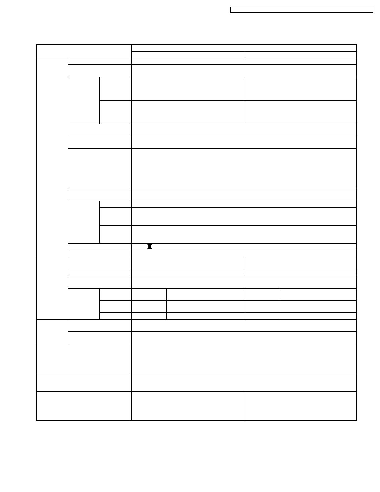
Panasonic KV-S2025C User manual

Type
User manual
© 2002 Kyushu Matsushita Electric Co., Ltd.
All rights reserved. Unauthorized copying and
distribution is a violation of law.
KV-S2025C Series
KV-SU225C Series
KV-S2045C Series
KV-SU245C Series
High Speed Color Scanner
ORDER NO. KM70206776C0
G14
1 GENERAL PRECAUTIONS 3
1.1. Safety Precautions
3
1.2. Electrical Tests
3
1.3. For Service Technicians
3
1.4. About Lead Free Solder (PbF: Pb free)
4
2 SPECIFICATIONS
5
2.1. KV-S2025C/S2045C Series
5
2.2. KV-SU225C/SU245C Series
6
3 COMPONENT IDENTIFICATION
7
4 INSTALLATION
8
4.1. Minimum Space Requirements
8
4.2. Installing Feed Extension Tray and Exit Extension Tray
(Only for KV-S2045C/SU245C Series)
8
4.3. Connecting the Scanner to a Personal Computer
9
4.4. System Requirements
9
4.5. SCSI Setting (Only for KV-S2025C/S2045C Series)
10
5 SECTIONAL VIEWS
11
5.1. CIS (Contact Image Sensor)
11
5.2. Rollers
12
5.3. Circuit Boards
13
5.4. Sensor Boards and Switch
14
6 MECHANICAL FUNCTION
15
6.1. Feed Mechanism for KV-S2025C/SU225C Series
15
6.2. Feed Mechanism for KV-S2045C/SU245C Series
16
7 MAINTENANCE
17
7.1. Maintenance Chart
17
7.2. Cleaning
17
7.3. Replacing Limited Life Parts
25
8 DISASSEMBLY INSTRUCTIONS
30
8.1. Disassembly Flowchart
30
8.2. Exterior
32
8.3. Unit Components
41
8.4. Circuit Board Assemblies
54
9 SERVICE UTILITY & SELF TEST
60
9.1. Main Menu Indication for Service Utility
60
9.2. Function item list of Service Utility
61
9.3. Operation
62
9.4. Scanner Self-test
68
10 TROUBLESHOOTING
69
10.1. Troubleshooting -1 (with no error message on PC)
69
10.2. Troubleshooting -2 (according to Error Code or Scanner
Status in Service Utility)
69
10.3. Requirement After Parts Replacement
79
11 CIRCUIT DESCRIPTION
80
11.1. Block Diagram - 1 (Image Processing)
80
11.2. Block Diagram - 2 (Board)
82
11.3. Explanation of Connector
83
12 CIRCUIT BOARDS
90
12.1. CONTROL Board
91
12.2. POWER Board
93
12.3. POWER SW Board
94
12.4. STARTING POSITION SENSOR Board
94
12.5. WAITING SENSOR Board
94
12.6. ENDING SENSOR Board
94
12.7. RELAY (FRONT) Board
95
12.8. RELAY (BACK) Board
95
12.9. LED Board
95
13 SCHEMATIC DIAGRAM
97
13.1. CONTROL Board
98
13.2. POWER Board, POWER SW Board
110
13.3. Sensors (Others)
113
14 PARTS LOCATION AND MECHANICAL PARTS LIST
115
14.1. Exterior
116
14.2. Chassis and Base
118
14.3. Hopper Unit
120
14.4. Power Unit
122
14.5. Packing
124
15 REPLACEMENT PARTS LIST
128
15.1. CONTROL Board
128
15.2. POWER Board
134
15.3. POWER SW Board
134
15.4. STARTING POSITION SENSOR Board
134
15.5. WAITING SENSOR Board
135
15.6. ENDING SENSOR Board
135
15.7. RELAY (FRONT) Board
135
15.8. RELAY (BACK) Board
135
15.9. LED Board
135
CONTENTS
Page Page
2
KV-S2025C Series / KV-SU225C Series / KV-S2045C Series / KV-SU245C Series
1 GENERAL PRECAUTIONS
1.1. Safety Precautions
1. Before servicing, unplug the power cord to prevent electrical shock hazard.
2. When replacing parts, user only manufacture’s recommended components for safety.
3. Check the condition of power cord. Replace if wear or damage is evident.
4. After servicing, be sure to restore the lead dress, insulation barriers, insulation papers, shields, etc.
5. Before returning the serviced equipment to the customer, perform the following electrical tests to prevent shock hazard.
1.2. Electrical Tests
1. Unplug the power cord and check for continuity between the earth ground connection on the plug and the metal cabinet. There
should be zero ohm resistance found.
2. With the unit unplugged, short the AC Live-Neutral of the plug with a jumper wire.
3. Turn ON the power switch.
4. Measure the resistance value with an ohmmeter between the jumpered AC plug and each exposed metal cabinet part, such as
screwheads, etc.
Note
Some exposed parts may be isolated from the chassis by design. They read infinity.
5. If the measurement is less than 1M , a possibility for electric shock may exit.
Note
This hazardous condition must be corrected before the unit is returned to the end user.
1.3. For Service Technicians
ICs and LSIs are vulnerable to static electricity.
When repairing, the following precautions will help to prevent recurring malfunctions.
1. Cover the plastic parts with aluminum foil.
2. Ground the soldering irons.
3. Use a conductive mat on the worktable.
4. Do not grasp IC or LSI pins with bare fingers.
3
KV-S2025C Series / KV-SU225C Series / KV-S2045C Series / KV-SU245C Series
1.4. About Lead Free Solder (PbF: Pb free)
Note
·
In the information below, Pb, the symbol for lead in the periodic table of elements, will refer to standard solder or
solder that contains lead.
·
We will use PbF when discussing the lead free solder used in our manufacturing process which is made from Tin
(Tn), Silver (Ag), and Copper (Cu).
·
This model, and others like it, manufactured using lead free solder will have PbF stamped on the PCB. For service
and repair work we suggest using the same type of solder although, with some precautions, standard Pb solder can
also be used.
Distinction of PbF PCB
·
PCBs (manufactured) using lead free solder will have a PbF stamp on the PCB.
Caution
·
PbF solder has a melting point that is 50° - 70°F, (30° - 40°C) higher than Pb solder.
Please use a soldering iron with temperature control and adjust it to 700° ± 20°F (370° ± 10°C). In case of using high
temperature soldering iron, please be careful not to heat too long.
·
PbF solder will tend to splash if it is heated much higher than its melting point, approximately 1100°F, (600°C).
·
If you must use Pb solder on a PCB manufactured using PbF solder, remove as much of the original PbF solder as
possible and be sure that any remaining is melted prior to applying the Pb solder.
·
When applying PbF solder to double layered boards, please check the component side for excess which may flow
onto the opposite side (See figure, below)
1.4.1. Suggested PbF Solder
There are several types of PbF solder available commercially. While this product is manufactured using Tin, Silver, and Copper,
(Tn+Ag+Cu), you can also use Tin and Copper, (Tn+Cu), or Tin, Zinc, and Bismuth, (Tn+Zn+Bi). Please check the manufacturer´s
specific instructions for the melting points of their products and any precautions for using their product with other materials.
The following lead free (PbF) solder wire sizes are recommended for service of this product: 0.3mm, 0.6mm and 1.0mm.
0.3mm × 100g 0.6mm × 100g 1.0mm × 100g
4
KV-S2025C Series / KV-SU225C Series / KV-S2045C Series / KV-SU245C Series
2 SPECIFICATIONS
2.1. KV-S2025C/S2045C Series
Item Model No.
*2 KV-S2025C Series *2 KV-S2045C Series
Scanner Scanning face Duplex
Scanning method CIS (Contact-type color image sensor) for Front & Back sides
Background: Black sensor roller
Readout
Speed *1
Simplex Black & White: 23 ppm
(Letter, Fed portrait, 200dpi)
Color: 10 ppm
(Letter, Fed portrait, 150dpi)
Black & White: 43 ppm
(Letter, Fed portrait, 200dpi)
Color: 19 ppm
(Letter, Fed portrait, 150dpi)
Duplex Black & White: 42 ipm
(Letter, Fed portrait, 200 dpi)
Color: 18 ipm
(Letter, Fed portrait, 150 dpi)
Black & White: 76 ipm
(Letter, Fed portrait, 200 dpi)
Color: 34 ipm
(Letter, Fed portrait, 150 dpi)
Resolution 100 - 600 dpi (10 dpi step)
Optical: 600 dpi (Main and Sub scanning directions)
Tonal gradation Binary mode, Gray scale mode (4 / 8 bit), Dither mode (16 / 256 step), Error diffusion
Note: Dither and Error diffusion are executed by driver or RTIV.
Image control Image emphasis (5step), Dynamic threshold, Automatic separation, Noise reduction, Deskew,
Cropping, Mirror Image, Monochrome Reversing, Gamma correction
Note:
·
Image emphasis: executed by Gate Array
·
Gamma correction for Black & White or Gray-scale: executed by Gate Array
·
Gamma correction for color RGB: executed by driver or RTIV
Other function Patch code detection (Kodak patch 2,3,T)
Note: 1 portion both side each executed only by ISIS driver.
Paper Size 50.8 × 70 mm (2.0 × 2.8 in.) to 216 × 356 mm (8.5 × 14 in.) *3
Thickness Single paper feeding: 0.05 to 0.15 mm (2.0 to 5.9 mils)
Continuous paper feeding: 0.06 to 0.15 mm (2.36 to 5.9 mils)
Note: 1 mil = 1 / 1000 in.
Weight Single paper feeding: 40 to 127g/m
2
(10.7 to 33.9 lbs.)
Continuous paper feeding: 50 to 127g/m
2
(13.3 to 33.9 lbs.)
Note: 1 lbs = 3.75 g/m
2
Interface (Transfer rate) SCSI (20 MB/sec)
Feed tray capacity 120 sheets [64 g/m
2
(17 lbs.)], 100 sheets [75 g/m
2
(20 lbs.)]
Unit External dimensions
(Width × Depth × Height)
343 × 487 × 269 mm (13.5 × 19.2 × 10.6 in.)
Note: When tray is pulled
343 × 487 × 239 mm (13.5 ×19.2 × 9.4 in.)
Note: When tray is installed
Weight 8.4 kg (18.5 lbs.) 9.1kg (20.1 lbs.)
Power requirement AC100 - 120 V, 50 / 60 Hz
AC220 - 240 V, 50 / 60 Hz
Power
consumption
Maximum
(Scanning)
AC100 - 240V 1A AC100 - 240V 1A
Minimum
(Standby)
AC100 - 240V 0.3 A AC100 - 240V 0.35 A
Sleep mode AC100 - 240V 0.1 A (7 W) AC100 - 240V 0.15 A (8 W)
Environment Operating temperature
and Humidity
Temperature: 15 °Cto30°C(59°Fto86°F)
Humidity: 30% to 80%RH
Storage temperature
and Humidity
Temperature: 0 °Cto35°C(32°Fto95°F)
Humidity: 10% to 80%RH
Accessories Power cord, Feed extension tray (Only for KV-S2045C Series), Exit extension tray (Only for KV-
S2045C Series), Roller cleaning paper, CD ROM (Maintenance, Safety and Installation manual,
Operation instructions, RTIV Capture software, ISIS driver, TWAIN driver, PIE manual, RTIV manual,
User utility, User utility manual), CD ROM (Paper Port SE: Only for KV-S2025C/CU), Printed document
(Maintenance, Safety and Installation manual)
PbF (Pb Free) Applied to PCB assemblies for KV-S2025C/S2045C Series KME will manufacture
Note: Distinction of PbF PCB
PCBs (manufactured) using lead free solder will have a PbF stamp on the PCB.
Option White roller kit (KV-SS023)
Roller exchange kit (KV-SS022)
Roller cleaning paper (KV-SS03)
White roller kit (KV-SS023)
Roller exchange kit (KV-SS022)
Roller cleaning paper (KV-SS03)
Imprinter unit (KV-SS020)
Ink cartridge (KV-SS021)
5
KV-S2025C Series / KV-SU225C Series / KV-S2045C Series / KV-SU245C Series
Note
·
*1: These values (Readout speed) depend on the test environment. The test environment by Manufacturer KME is
as follows.
PC Environment
OS: Windows NT
®
4.0 / CPU: Pentium
®
300MHz / Amount of Memory: 256MB / SCSI Card: 2940AU /
Software: Twain 1.00
Setting of Twain is default.
Display scanned image to screen.
No file saving.
Count fed paper in 1 minute from 2nd page.
·
*2: Suffix
No suffix: U.S.A. and other countries where power supply (AC100 to AC120V) is applied.
U: Europe and other countries where power supply (AC220 to AC240V) is applied except for China.
CN: For China.
·
*3: The setting of the paper length is possible to 25 inches in TWAIN, ISIS, and RTIV.
In case of a paper beyond legal size, 1 by 1 paper scanning in the resolution under 300dpi is recommended.
2.2. KV-SU225C/SU245C Series
Item Model No.
KV-SU225C Series KV-SU245C Series
To Be Continued To Be Continued To Be Continued
Note
Supplement service manual will mention detail information on the above specification.
6
KV-S2025C Series / KV-SU225C Series / KV-S2045C Series / KV-SU245C Series
3 COMPONENT IDENTIFICATION
Imprinter Door
Paper Feed Case
ADF Door
Document Guide
Feed Tray
Exit Tray
Exit Extension Tray
Exit Stopper
Feed Extension Tray
Business Card Guide
Business Card Stopper
ADF Door
Release
STOP / START
Button
Radiation Vent
Power Switch
DIP Switch
Power Cord
(This illustration is
a sample figure for
AC100 - 120V)
AC Inlet
Connectors
Color ON
Green
Orange
Red
1. Ready
2. Scanning
*1. Ready with
warning error
*2. Scanning with
warning error
An error occurred
Flashing
Sleeping without
warning error
1. Initializing
*2. Sleeping with
warning error
3. Shading
System error
LED (for indicating scanner status)
Note
* Warning error: Clean roller or replace roller
7
KV-S2025C Series / KV-SU225C Series / KV-S2045C Series / KV-SU245C Series
4 INSTALLATION
4.1. Minimum Space Requirements
Be sure to maintain the recommended space requirements for proper ventilation.
4.2. Installing Feed Extension Tray and Exit Extension Tray (Only for KV-
S2045C/SU245C Series)
Take out the Feed Extension Tray and Exit Extension Tray in the accessory carton box, and install them as shown below.
Note
Don’t carry the scanner with the Feed Extension Tray and the Exit Extension Tray.
Be sure to remove the trays before carrying the scanner.
8
KV-S2025C Series / KV-SU225C Series / KV-S2045C Series / KV-SU245C Series
4.3. Connecting the Scanner to a Personal Computer
4.3.1. KV-S2025C/S2045C Series
Fig. 4.3.1
Note
Power Cord shown on the Fig. 4.3.1 is for AC100-120V.
Caution
1. Use the Power Cord that is supplied with the scanner manufacturer.
2. Use SCSI cables as short as possible, securing SCSI specification.
3. After turning off the scanner and PC, remove SCSI cables.
4.4. System Requirements
4.4.1. KV-S2025C/S2045C Series
CPU Minimum: Pentium
®
300MHz
Recommended: Pentium
®
800MHz or higher
Memory (RAM) [Black & White Scanning]
Minimum: 128MB
Recommended: 256MB or higher
[Color Scanning]
Minimum: 256MB
Recommended: 512MB or higher
OS Windows
®
95 / Windows
®
98 / Windows
®
Me / Windows NT
®
/ Windows
®
2000 / Windows
®
XP
SCSI Board Adaptec SCSI card 2930U / 2940U / 29160N / 19160
Note
The scanning speed differs depending on the personal computer´s operating environment or application.
9
KV-S2025C Series / KV-SU225C Series / KV-S2045C Series / KV-SU245C Series
4.5. SCSI Setting (Only for KV-S2025C/S2045C Series)
Set SCSI ID and Terminator on the DIP Switch whose layout is shown on Fig. 4.5.1.
Fig. 4.5.1
4.5.1. SCSI ID
Referring to the following Fig. 4.5.2, be sure to set a scanner´s SCSI ID number of the DIP Switch, different from the other SCSI
device in the SCSI chain.
Fig. 4.5.2
SCSI ID
Number
DIP Switch Setting Remarks
ID2 ID1 ID0
0 OFF OFF OFF
1 OFF OFF ON
2 OFF ON OFF
3 OFF ON ON
4 ON OFF OFF
5 ON OFF ON
6 ON ON OFF KME Factory Default
7 ON ON ON
Note
It is not until restarting the PC after restarting the scanner that Setting "SCSI ID" will be activated.
4.5.2. Terminator
According to the SCSI interface condition, set the Terminator (TERM) ON or OFF.
Note
1. If the scanner is the last or the only device in the SCSI chain, the terminator should be set to "ON".
2. It is not until restarting the PC after restarting the scanner that Setting "Terminator ON or OFF" will be activated.
10
KV-S2025C Series / KV-SU225C Series / KV-S2045C Series / KV-SU245C Series
5 SECTIONAL VIEWS
5.1. CIS (Contact Image Sensor)
Sensor Roller (Back)
Sensor Roller (Front)
CIS (Back)
CIS (Front)
Imprinter (Option)
(KV-S2045C/SU245C Series only)
Conveyor Motor
Paper Feed Motor
11
KV-S2025C Series / KV-SU225C Series / KV-S2045C Series / KV-SU245C Series
5.2. Rollers
Exit Roller
Drive Rollers
Retard Roller
Separation Roller
Paper Feed Roller
12
KV-S2025C Series / KV-SU225C Series / KV-S2045C Series / KV-SU245C Series
5.3. Circuit Boards
LED Board
RELAY (BACK) Board
RELAY (FRONT) Board
CONTROL Board
POWER Board
POWER SW Board
(Power Switch)
13
KV-S2025C Series / KV-SU225C Series / KV-S2045C Series / KV-SU245C Series
5.4. Sensor Boards and Switch
ENDING SENSOR Board
(Ending Sensor)
STARTING POSITION
SENSOR Board
(Starting Position Sensor)
Door Switch
WAITING SENSOR Board
(Waiting Sensor)
Paper Detector
14
KV-S2025C Series / KV-SU225C Series / KV-S2045C Series / KV-SU245C Series
6 MECHANICAL FUNCTION
6.1. Feed Mechanism for KV-S2025C/SU225C Series
1. Scanning command is issued from PC, Paper detector checks whether documents exist on the Feed Tray.
2. Conveyor Motor is driven to rotate Drive Rollers.
3. Paper Feed Motor is driven to rotate Paper Feed Roller and Separation Roller.
Retard Roller is supported by a shaft fixed via torque limiter, and it is pressed against the Separation Roller.
When documents enter into the separation section, the Retard Roller exerts a manipulation force onto the document with the
torque which has been already set.
This Manipulation force enables to separate the documents, and to feed a piece of document to scanning section.
4. When the leading edge of the document advances at about 10mm from the 1
st
Drive Roller after passing through the separation
section and Waiting Sensor, the Paper Feed Motor stops and the Paper Feed Roller and Separation Roller turn together.
5. When the leading edge of the document passes through Starting Position Sensor, scanning the image starts after the defined
period. (Time to be required to conveyor the documents from the Starting Position Sensor to the scanning start point)
6. When the heeling edge of the document comes to about +5mm forward from the Retard Roller whose length is equivalent to
the distance between the Starting Position Sensor and the scanning start point, the Paper Feed Motor is driven again to feed
the 2
nd
document.
7. Repeat the sequence "3." to "6.".
Note
When buffer memories in the scanner are full of the image data during scanning, the scanner stops scanning
(conveying) to wait until the free memorized space is secured for a moment.
When the free memorized space is secured, the scanner starts scanning again.
15
KV-S2025C Series / KV-SU225C Series / KV-S2045C Series / KV-SU245C Series
6.2. Feed Mechanism for KV-S2045C/SU245C Series
6.2.1. In case the data size of a document is over the amount of the memory in the
scanner.
Same sequence as the above 6.1. says.
Note
When buffer memories in the scanner are full of the image data during scanning, the scanner stops scanning
(conveying) to wait until the free memorized space is secured for a moment.
When the free memorized space is secured, the scanner starts scanning again.
6.2.2. In case the data size of a document is within the amount of the memory in the
scanner.
1. Same sequence as the above sequence "1" of the 6.1 says.
2. Same sequence as the above sequence "2" of the 6.1 says
3. Same sequence as the above sequence "3" of the 6.1 says
4. Same sequence as the above sequence "4" of the 6.1 says
5. Same sequence as the above sequence "5" of the 6.1 says
6. After finishing the 1
st
document scanning, the Paper Feed Motor is driven to feed the 2
nd
document again.
7. Repeat the sequence "3." to "6."
16
KV-S2025C Series / KV-SU225C Series / KV-S2045C Series / KV-SU245C Series
7 MAINTENANCE
7.1. Maintenance Chart
C: Clean R: Replace (×1000 sheets)
Description ReferenceofPartNo. 20 40 60 80 - 260 280 300
Paper Feed Roller Ref. No. 52 in Sec.14.3 C C C Clean each part every 20 (× 1000)
sheets’ scanning.
C R
Separation Roller Ref. No. 45 in Sec.14.3 C C C C R
Retard Roller Ref. No. 16 in Sec.14.1 C C C C R
Drive Roller 1 Ref. No. 36 in Sec.14.2 C C C C C
Drive Roller 2 Ref. No. 36 in Sec.14.2 C C C C C
Drive Roller 3 Ref. No. 36 in Sec.14.2 C C C C C
Exit Roller Ref. No. 36 in Sec.14.2 C C C C C
CIS For front side Ref. No. 26 in Sec.14.3 C C C C C
For back side Ref. No. 53 in Sec.14.2 C C C C C
Sensor Roller For front side Ref. No. 72 in Sec.14.2 C C C C C
For back side Ref. No. 33 in Sec.14.3 C C C C C
Free Roller Ref. No. 32 in Sec.14.1 C C C C C
Ref. No. 18 in Sec.14.3
Paper Detector Ref. No. 22 in Sec.14.1 C C C C C
Waiting Sensor Ref. No. 1 in Sec.14.3 C C C C C
Starting Position Sensor Ref. No. 7 in Sec.14.3 C C C C C
Ending Sensor Ref. No. 37 in Sec.14.2 C C C C C
Reflector Sheet for Waiting Position Sensor Ref. No. 63 in Sec.14.2 C C C C C
Reflector Sheet for Starting Position Sensor Ref. No. 63 in Sec.14.2 C C C C C
Reflector Sheet for Ending Sensor Ref. No. 35 in Sec.14.1 C C C C C
Note
·
The above values for each maintenance item are registered in the maintenance counter (Refer to Sec. 9), and the
PC will inform users the cleaning or replacing timing if the utility software in this scanner has been already
installed.
·
The maintenance schedule was determined according to paper standards (A4 or Letter, 16lb copier paper), which
can vary greatly between users. Therefore, the values can also vary.
7.2. Cleaning
When cleaning rollers and CIS Sec. 7.2.1. mentions, the accessory Roller Cleaning Paper or Model KV-SS03 (Option: Roller
Cleaning Paper) is needed.
Note
1. Roller Cleaning Paper
·
Open the bag by the dotted line and take out the Roller Cleaning Paper.
·
If the opened bag is left open for a long period of time before using it, the alcohol will evaporate. Please use the
Roller Cleaning Paper immediately after opening the bag.
·
The Roller Cleaning Paper (Model No. KV-SS03) is available via sales route.
2. When ADF Door does not open even if ADF Door Release is pushed repeatedly, there is possibility that the door
does not close enough. In this case, try to close the ADF Door until it clicks into place.
17
KV-S2025C Series / KV-SU225C Series / KV-S2045C Series / KV-SU245C Series
7.2.1. Cleaning Paper Feed Roller, Separation Roller, and Retard Roller
(1) Turn off the scanner.
(2) Push the ADF Door Release to open the ADF Door.
(3) Wipe off the dirt on the surfaces of the Paper Feed Roller
and Separation Roller with the accessory Roller Cleaning
Paper or Model KV-SS03 (Option: Roller Cleaning Paper).
Note
When wiping off the dirt on the roller surfaces, hold
the rollers to prevent from rotating, and wipe the
rollers all the way around them proceeding from one
end to the other in the direction of the arrows shown
in the figure.
(4) Remove the Retard Roller Cover in the direction of the
arrow shown in the figure.
18
KV-S2025C Series / KV-SU225C Series / KV-S2045C Series / KV-SU245C Series
(5) Clean the surface of the Retard Roller with the accessory
Roller Cleaning Paper or Model KV-SS03 (Option: Roller
Cleaning Paper).
When cleaning it, wipe off the dirt on the roller surface all
the way around it proceeding from one end to the other in
the direction of the arrow shown in the figure.
(6) And then, assemble the Retard Roller Cover.
(7) Close the ADF Door slowly until it clicks into place.
Note
After cleaning the above rollers, execute "Clear Counter" for cleaning roller in Service Utility. (See 9.3.4.)
19
KV-S2025C Series / KV-SU225C Series / KV-S2045C Series / KV-SU245C Series
7.2.2. Cleaning Driver Rollers and Free Rollers
(1) Turn off the scanner.
(2) Push the ADF Door Release to open the ADF Door.
(3) Wipe off the dirt on the surfaces of the Drive Rollers in the
direction of the arrows shown in the figure with the
accessory Roller Cleaning Paper or Model KV-SS03
(Option: Roller Cleaning Paper).
(4) Clean the surfaces of the Free Rollers with the accessory
Roller Cleaning Paper or Model KV-SS03 (Option: Roller
Cleaning Paper).
When cleaning them, wipe off the dirt on the roller surfaces
all the way around them proceeding from one end to the
other in the direction of the arrows shown in the figure.
20
KV-S2025C Series / KV-SU225C Series / KV-S2045C Series / KV-SU245C Series
  • Page 1 1
  • Page 2 2
  • Page 3 3
  • Page 4 4
  • Page 5 5
  • Page 6 6
  • Page 7 7
  • Page 8 8
  • Page 9 9
  • Page 10 10
  • Page 11 11
  • Page 12 12
  • Page 13 13
  • Page 14 14
  • Page 15 15
  • Page 16 16
  • Page 17 17
  • Page 18 18
  • Page 19 19
  • Page 20 20
  • Page 21 21
  • Page 22 22
  • Page 23 23
  • Page 24 24
  • Page 25 25
  • Page 26 26
  • Page 27 27
  • Page 28 28
  • Page 29 29
  • Page 30 30
  • Page 31 31
  • Page 32 32
  • Page 33 33
  • Page 34 34
  • Page 35 35
  • Page 36 36
  • Page 37 37
  • Page 38 38
  • Page 39 39
  • Page 40 40
  • Page 41 41
  • Page 42 42
  • Page 43 43
  • Page 44 44
  • Page 45 45
  • Page 46 46
  • Page 47 47
  • Page 48 48
  • Page 49 49
  • Page 50 50
  • Page 51 51
  • Page 52 52
  • Page 53 53
  • Page 54 54
  • Page 55 55
  • Page 56 56
  • Page 57 57
  • Page 58 58
  • Page 59 59
  • Page 60 60
  • Page 61 61
  • Page 62 62
  • Page 63 63
  • Page 64 64
  • Page 65 65
  • Page 66 66
  • Page 67 67
  • Page 68 68
  • Page 69 69
  • Page 70 70
  • Page 71 71
  • Page 72 72
  • Page 73 73
  • Page 74 74
  • Page 75 75
  • Page 76 76
  • Page 77 77
  • Page 78 78
  • Page 79 79
  • Page 80 80
  • Page 81 81
  • Page 82 82
  • Page 83 83
  • Page 84 84
  • Page 85 85
  • Page 86 86
  • Page 87 87
  • Page 88 88
  • Page 89 89
  • Page 90 90
  • Page 91 91
  • Page 92 92
  • Page 93 93
  • Page 94 94
  • Page 95 95
  • Page 96 96
  • Page 97 97
  • Page 98 98
  • Page 99 99
  • Page 100 100
  • Page 101 101
  • Page 102 102
  • Page 103 103
  • Page 104 104
  • Page 105 105
  • Page 106 106
  • Page 107 107
  • Page 108 108
  • Page 109 109
  • Page 110 110
  • Page 111 111
  • Page 112 112
  • Page 113 113
  • Page 114 114
  • Page 115 115
  • Page 116 116
  • Page 117 117
  • Page 118 118
  • Page 119 119
  • Page 120 120
  • Page 121 121
  • Page 122 122
  • Page 123 123
  • Page 124 124
  • Page 125 125
  • Page 126 126
  • Page 127 127
  • Page 128 128
  • Page 129 129
  • Page 130 130
  • Page 131 131
  • Page 132 132
  • Page 133 133
  • Page 134 134
  • Page 135 135

Panasonic KV-S2025C User manual

Type
User manual

Ask a question and I''ll find the answer in the document

Finding information in a document is now easier with AI