Page is loading ...

Keep this manual near the navien Combination Boiler
for future reference whenever maintenance or service
is required.
CH-180 ASME
CH-210 ASME
CH-240 ASME

Installation Manual - Contents
Accessories
Specifications
Components & Dimensions
Warinings
Rating Plate
Location Selection
Plumbing
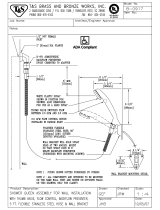
Pressure Relief Valve
Condensate Disposal
Gas Piping
Gas Pressure Testing
Venting
Pressure Reducing v/v
Outdoor Temp. Sensor
Electrical Connection
Remote Controller
Installation
PCB Board Setting
Cascade Connection and
Set-up Procedure
DIP Switch Setting
Installation Checklist
Maintenance
Factory Setting of
Dip Switch
Completing the Install
Wiring Diagram
Ladder Diagram
Wiring Information
Components Diagram &
Parts List
Included with the Combination Boiler 3
Optional Accessories 4
5
Key Components 6
Dimensions 7
Installation Warning 8
Getting Started 10
Check Rating Plate 11
Locating the Combination Boiler 12
Mounting the Unit to the Wall 13
Plumbing and Water Connection Guideline 14
Plumbing Guideline 17
26
Disposal of Condensate 27
Condensate Drain & Cleaning 28
Gas Piping Guideline 29
Gas Supply Line Pressures 29
Gas Piping Sizing Chart 31
Measuring Inlet Gas Pressure 33
Warning 34
Venting Guideline 34
Contaminated Make-up Air Will Damage the Unit 37
Exhaust Pipe Materials 37
Venting Clearances 39
Allowable Vent Lengths 40
Vent Configuration Options 41
Concentric Vent Termination 43
45
Outdoor Temp. Sensor Installation 47
Outdoor Temp. Sensor Installation Guideline 47
K-Factor 48
50
51
52
53
58
61
65
66
66
67
68
69
71

Description
Qty
Navien
Condensing
Combination
Boiler
1
Remote Controller
1
Operation and
Installation
Manual
1
Wall Mounting
Bracket
1
Condensate Drain
Hose
1
Tapping Screws &
Anchors
4
Vent terminators
2
Wall Flanges
4
Pressure
Reducing Valve
Kit
3
Accessories:
Check that you have received all of the above parts before installing the
Combination Boiler.
Included with the Combination Boiler:
Item
3

Description
Navien Plumb Easy Valve Set
(Pressure Relief Valve) – Heating
Navien Plumb Easy Valve Set
(Pressure Relief Valve) –
Domestic Water
Navien Condensate Neutralizer
Navien Ready-Link Communication Cable
Outdoor Temperature Sensor with Cable
Optional Accessories:
Contact your Navien combination Boiler supplier for optional
accessories.
Optional Accessories:
Item
4

Flow Rate (DHW)
77ı(43ç) Temp Rise
3.4 GPM 4.0 GPM 4.5 GPM

No Description Navien Part No. No Description Navien Part No.
1
2
3
4
5
6
7
8
9
10
11
12
13
14
15
16
17
18
19
20
21
22
23
24
25
26
Intake Air Duct
Fan Motor
WPS
DHW Heat Exchanger
S/H Strainer
Motorized 3-Way Valve
Circulation Pump
S/H Supply Adaptor
S/H Return Adaptor
PCB Board
DHW Cold Water InletAdapter
Auto Feeder Valve
Main Gas Valve
BH2505400B
NAFA9GLPCT01
BH2507535A
PAS30KHE_004
BH1301020B
AAVC9EX00018
NAPU9GLPCT10
BH2507639A
BH2507639A
NACR1GS32301
30010315A, 30010316A,
30010317A
30005993C
BH0901018A
DHW Flow Sensor
Syphon
Transformer
Gas Pressure Sensor
Gas Pipe
Secondary Heat Exchanger
Primary Heat Exchanger
APS Venturi
Burner
Ignition Transformer
Air Pressure Sensor
Exhaust Duct
Exhaust Pipe
BH1406005A
BH2501442C
BH1205011A
NASS9EXGPS01
BH2546021A
-
-
BH2501413A
PABNCW48KDN_002
BH1201045A
NASS9EX00009
BH2544007D
BH2505401B
Key Components: CH
NAVIEN Combination Boiler
6

Dimensions: CH Models
Description Diameter
Exhaust Pipe
Intake Air Duct
Space Heating
Supply Connection
Auto Feeder
Connection
Gas Inlet Connection
Space Heating
Return Connection
DHW Supply
Connection
DHW Cold Water
Inlet Connection
3"
3"
1"
1"
3/4"
3/4"
1/2"
3/4"
A
B
C
D
E
F
G
H
CH
7
%
$
&
' (
)

Installation Warnings:
8
Read all safety warnings in the “User’s Operation Manual”. The additional safety
issues outlined below must also be followed completely when installing this Navien
Combination Boiler.
1.
2.
3.
4.
5.
6.
7.
All applicable local, state, national and provincial codes, ordinanes, regulations and laws.
For installations in Messachusetts – code requires the boiler to be installed by a licensed
plumbing or gas fitter.
The National Fuel Gas Code NFPA 54/ ANSI Z223.1
National Electric Code ANSI/NFPA 70.
For Installations in Canada – “Installation Code for Gas Burning Eqiupment” CGA/B 149.1 or
B149.2 Canadian Electrical Code Part 1 CSA C22.1
Standard for Controls and satety devices for automatically fired boilers, ANSI/ASME CSD-1,
when requred.
The installation must conform to the requirements of the authority having jurisdiction or, in
the absence of such requirements, to the National Fuel Gas Code, ANSI Z223.1/NFPA 54
and/or CAN/CSA B149.1, Natural Gas and Propane Installation Code.
8.
9.
10.
11.
12.
13.
14.
This unit is designed for indoor/outdoor installations. DO NOT operate this unit without the
vent piping connected. Exhaust gases must be completely expelled out of the building.
DO NOT use this appliance if any part has been underwater. Immediately call a qualified
service technician to inspect the appliance and replace any part of the control system and
any gas control which has been underwater.
Be sure not to reverse the water and gas connections as this may damage the gas valves.
Water temperature over 125°F can cause severe burns instantly or death from scalding.
If the proposed Boiler outlet temperature is above 125°F, a thermostatically controlled
mixing valve (or a temperature limiting valve) for reducing point of use water temperature is
recommended to reduce the risk of scald injury. Contact a licensed plumber or the local
plumbing authority for further information.
The appliance should be located in an area where leakage within the unit or at its
connections will not result in damage to the surrounding area. Navien will not be responsible
for any damage resulting from leaking if adequate drainage is not provided.
DO NOT use this combination Boiler for any purpose other than water heating and space
heating.
If the water quality is known to be highly acidic and/or extremely hard, water treatments
(i.e water softners) are recommended to maintain full warranty. Consult the local water
authority.
Failure to remove or maintain the area free of combustible material, gasoline
and other flammable liquids or vapors can result in severe personal, injury,
death or substantial property damage.
Follow all local codes and/or the most recent edition of the National Fuel Gas
Code (ANSI Z223.1/NFPA 54) in the USA or the Natural Gas and Propane
Installation Code in Canada (CAN/CGA B149.1).

Installation Warnings:
9
Protect against snow accumulation around the vent terminations. Ensure the exhaust pipe
and the intake air pipe remain clear from obstructions at all times.
DO NOT overtighten fittings as pipe and/or fitting damage may occur causing leakage.
DO NOT install the combination Boiler where subject to vibrations.
The vent for this appliance shall not terminate over public walkways, or near soffit vents,
crawl space vents and other areas where condensate or vapor could create a nuisance,
hazard or cause property damage. Or where condensate and vapor could cause damage
to or could be detrimental to the operation of regulators, relief valves, or other equipment.
For other than a direct vent appliance, the appliance must be located as close as possible
to a chimney or gas vent.
Should overheating occur or the gas supply fails to shut off, turn off the manual gas control
valve to the appliance. Contact a Service Technician immediately.
The gas connections and water connections must be leak tested before placing into operation.
After placing into operation the ignition safety device must be tested.
Visually inspect the venting system for proper size and horizontal pitch and determine
there is not blockage or restriction, leakage, corrosion and other deficiencies which could
cause an unsafe condition.
Insofar as is practical, close all building doors and windows and all doors between the
space in which the appliances remaining connected to the common venting system are
located and other space of the building. Turn on cloths dryers and any appliance not
connected to the common venting system. Turn on any exhaust fans, such ar range hoods
and bathroom exhausts, so they will operate at maximum speed. Do not operate a summer
exhaust fan. Close fireplace dampers.
Place in operation the appliance being inspected. Follow the lighting instructions. Adjust
thermostat so appliance will operate continuously.
After it has been determined that each appliance remaining connected to the common
venting system properly vents when tested as outlined above, return doors, windows,
exhaust fans, fireplace dampers and any other gas-burning appliance to their pervious
condition of use.
Any improper operation of the common venting system should be corrected so the installation
conforms with the National Fuel Gas Code, ANSI Z223.1/NFPA 54 and/or CAN/CSA
B149.1, Natural Gas and Propane Installation Code. When resizing any portion of the
common venting system, the common venting system should be resized to approach the
minimum size as determined using the appropriate tables in Appendix F in the National
Fuel Gas Code, ANSI Z223.1/NFPA 54 and/or CAN/CSA B149.1, Natural Gas and
Propane Installation Codes.
The instructions for the installation of the venting system shall specify that the horizontal
portions of the venting system shall be supported to prevent sagging; the methods of and
intervals for support shall be specified. These instructions shall also specify that the venting
system:
■
For Category I, II and IV boilers, have horizontal runs slopping upwards not less than 1/4
inch per foot (21 mm/m) from the boiler to the vent terminal;
■
For Category II and IV boilers, be installed so as to prevent accumulation of condensate; and
■
For Category II and IV boilers, where necessary, have means provided for drainage of
condensate.
“Caution: Label all wires prior to disconnection when servicing controls. Wiring errors can
cause improper and dangerous operation.”
“Verify proper operation after operation servicing.”
15.
16.
17.
18.
19.
20.
21.
22.
23.
24.
25.
26.
27.
28.
29.
30.

Getting Started:
CHECK THE RATING PLATE
Be sure the gas type and electricity voltage
match the Rating Plate.
Use only the gas type indicated on the
rating plate of the Navien Combination
Boiler. Using a different gas type will
cause abnormal combustion and Boiler
malfunction.
Be sure to use 120VAC 60Hz minimum 2A
current. Using abnormally high or low AC
voltage may cause abnormal operation,
and may reduce the life expectancy of this
product.
If not certain, please contact Navien immediately.
Navien America Inc. is not liable for any property damage and/or personal
injury resulting from unauthorized conversions.
10
Navien units come from the factory configured for use with either Liquid Propane
(LP) or Natural Gas (NG). Before starting the installation, check the rating plate
(side of unit) of the combination Boiler to ensure the unit matches gas type, gas
pressure, water pressure and electrical supply. If the unit does not match the
following requirements, Do Not Install.
The appliances comply with SCAQMD 2012 requirements.
NOx emission level of less than 14 nanograms of NOx (calculated as NO
2) per joule
of heat output or less than or equal 20 ppm of NOx emissions (at 3% O
2 dry).
Conversion of this unit from natural gas to propane or vise versa cannot be done in
the field. Please re-confirm gas type on the rating plate (side of unit) before install-
ing. DO NOT attempt any field conversion; this will result in dangerous operating
conditions and will void all warranty.

Check Rating Plate
Sample Rating Plate
DO NOT install the unit in a location where there is
excessive high humidity such as a bathroom,
damp crawl space and other areas such as this.
This may cause the unit to malfunction.
To avoid possible electrical shock, DO NOT touch
the internal components of the combination boiler
or the power plug with wet hands.
DO NOT splash excessive water on the
combination boiler or remote controller when
cleaning; they are water resistant, not water proof.
DO NOT install the Navien Combination Boiler in areas with excessive high
humidity:
11

Locating the Combination Boiler:
WARNING
Considering the Location “ in accordance to ANSI Z223.1/
NFPA 54 and/or CAN/CSA B149.1 Gas Installation Code”
Location selection may not necessarily affect the operation of the Navien
Combination Boiler but it will affect the customer’s experience and level of
satisfaction with the product. Understanding that each building is different,
the contractor will have to select the best location based on a combination of
the following factors:
Locate the Navien Combination Boiler close to a drain where condensed water
and possible water leakage will not do damage to surrounding areas. A significant
amount of condensed water will be produced each time the combination boiler is
used. In addition, as with any water heating appliance, the potential for leakage
at some time in the life of the product does exist. If there is no drain, Navien will
not be responsible for any water damage that may occur.
Locate the main fixtures in the home (bathrooms, kitchen, laundry, etc.). Select a
location that minimizes the water piping distance between the major fixtures.
Consider venting options: Select a location that minimizes the amount of venting
required. Consider venting restrictions from windows, doors, air intakes, gas meters,
neighbor’s house, etc.
Maintain proper clearances from any openings in the building (see chart in
venting section).
Navien combination boiler requires a minimum clearance of 12 inches above
the exterior grade..
Do not install the boiler where moisture from the exhaust may cause discoloration
or damage to walls.
Install the exhaust vent so that there are no obstacles around the termination
and so that exhaust cannot accumulate.
Do not enclose the termination.
Do not install the combination boiler near vents for heating or cooling. A minimum
distance of 4 feet (1.2m) should be maintained.
It is not recommended to install the combination boiler in bathrooms, bedrooms,
any occupied rooms normally kept closed, or in indoor areas without proper
venting.
This boiler must not be installed over carpeting.
Locate where the city water supply comes into the building.
Locate where the gas supply comes into the building.
12


The piping materials used should meet local codes and industry standards.
Piping must be cleaned and flushed-out before installation.
Do not apply torch heat within 12" of the bottom connections of the unit.
Perform all solder connections at a safe distance from the (brass) male connectors
below the unit. Allow fittings to cool, before attaching to unit. Use only approved
coupling unions with O-rings to attach field piping to unit.
The ‘heating’ pipe should be 1" or bigger diameter copper or PEX. Never use aluminum,
PVC or galvanized steel piping.
The pipe size used for supply heating water should be the same size used for the
return heating water.
Use only copper piping with lead-free solder for the domestic water side.
The size of the domestic hot water pipe should be 1" diameter.
The length of piping should be as short as possible and the piping should have minimal
number of bends and connections.
Use only ball type isolating valves. Do not use gate valves.
Never leave the heating pipes disconnected while operating the unit as a Combination
Boiler. This will cause damage to the heat exchanger and void the manufacturers
warranty.
All piping should be insulated.
After making the piping connections, check for gas or water leaks.
If the water supply pressure is 142 psi or higher, install the water pressure regulator
on the water supply piping.
14
Do Not open the Auto Feeder Connection cap, unless the pipe is connected
to the Auto Feeder valve.
CAUTION
Plumbing:
Plumbing and Water Connection Guidelines

With clean, potable water free of corrosive chemicals, sand, dirt, or other contaminates.
With inlet water temperatures above 32°F(0°C), but not exceeding 140°F(60°C).
Free of lime and scale deposits.
Navien Combination Boiler is equipped with a factory installed pressure sensor
type Low Water Cut Off device.
The Mininum operation system pressure allowable with this device is 7 psig.
Check local code if a Low Water Cut Off is requred. If so, determine if this device
meets the requirements of the local codes.
If a separate LWCO device is required by certain local jurisdications or when the
Navien Combination Boiler is installed above the system piping, the following
guidelines must be followed:
- The LWCO device must be installed in a tee connection on the Boiler /supply
piping above the Boiler.
1.
2.
3.
4.
Use a backflow preventer valve in the make-up water supply to the unit as
required by local codes.
Space heating system freeze protection products may be used in lieu of product
referenced above. In general, freeze protection for new or existing systems must
use specially formulated glycol, which contains ingibitors, preventing the glycol
from attacking the metallic system components. Insure that system fluid contains
proper glycol concentration and ingibitor level.
The system should be tested at least once a year and as recommended by the
manufacturer of the glycol solution. Allowance should be made for expansion of
the gloycol solution.
15
WARNING
Plumbing:
Failure to properly pipe Boiler may result in improper operation and damage to the
Combination Boiler or structure.
CAUTION
This Combination Boiler must only be used with the following water supply
system conditions.
CAUTION
If the installation is to comply with ASME or Canadian requirements, an additional
high temperaure limitation device may be needed. Consult local code
requirements to determine compliance.
CAUTION
Use only inhibited propylene glycol solutions specifically formulated for hydronic
systems. Do not use ethylene glycol, which is toxic and can attack gaskets and
seals used in hydronic systems.
Low Water Cut Off device
Backflow Preventer
Space Heating Freeze Protection

Diaphragm Expansion Tank
Closed-Type Expansion Tank
Plumbing
16
Expansion Tank
The expansion tank must be located as shown in A~F basic application
drawings.(page 20 ~ 25) (Refer to the expansion tank manufacturer’s
instructions for additional installation details.)
Always locate and install the system fill connection at the same location as the
expansion tank’s connection to the system.
If the expansion tank must be replaced, consult the expansion tank
manufacturer’s literature for proper sizing.
Always install an automatic air vent on the top of the air separator to remove
residual air from the system.
It is recommanded to pitch any horizontal piping upward toward the expasion
tank 1 inch per 5 feet of piping.
Use 3/4" piping for the expansion tank to allow air within the system to rise.
Connect the expasion tank to an air separator only if the air separator is located
on the suction side of the system circulator.
CAUTION
Do not install automatic air vents on a closed-type expansion tank system.
Air must remain in the system and be returned to the expansion tank to provide
an air cushion.

17
Plumbing: Guide Line
Case I. With backflow preventer Installation
If using mixing valves on the domestic hot water outlet, choose one which
prevents cold water pressure from overcoming hot water line pressure.
The flow rate of hot water may vary when more than two faucets (appliances,
fixtures, etc.) are being used simultaneously.
If a combination Boiler is installed in a closed water supply system, such as
one having a backflow preventer in the cold water supply line, means shall be
provided to control thermal expansion device. Contact the water supplier or
local plumbing inspector on how to control this situation.
NOTICE :
CAUTION
This drawing can be a useful guideline when installing a unit. However, installation may vary
depending on the location circumstances, local building codes or state regulation. Ma ke sure to
check the local building codes and state regulation before installation, and comly with it.
As shown above, Navien recommends installing the water supplement plumbing.
Water Supplement
DHW Cold
Water Inlet
DHW Supply
Secondary Loop (Heating)
Primary Loop (Heating)
Legend
Expansion Tank
Air Seperator
Circulation Pump
Hydro Tee
Manual Valve
Regulator
Check valve
Backflow Preventer

Plumbing Guideline
18
Plumbing
Case II. Non-backflow preventer Installation
If using mixing valves on the domestic hot water outlet, choose one which prevents cold
water pressure from overcoming hot water line pressure.
Hot water Temperature may vary when more than two faucets (appliances, fixtures, etc.)
are being used simultaneously.
NOTICE :
Water Supplement
Auto Feeder
Valve
DHW Cold
Water Inlet
Domestic Water
Supply Line
Secondary Loop (Heating)
Primary Loop (Heating)
Legend
Expansion Tank
Air Seperator
Circulation Pump
Hydro Tee
Manual Valve
Regulator
Check valve
Backflow Preventer

CAUTION
Do Not open the Auto Feeder Connection cap, unless the pipe is connected to
the Auto Feeder valve.
As shown above, Navien’s have to establish the water supplement plumbing is
not recommended.
Case III. Non-Auto supplement backflow preventer Installation
Water Supplement
DHW Cold
Water Inlet
DHW Supply
19

20
Plumbing :
A . In-Floor Heating (Zoning Control) System (with Wiring Diagram)
Wiring Daigram
Water Supplement
DHW Cold
Water Inlet
DHW Supply
/