Page is loading ...


Installation Manual - Contents
Accessories Included with the
Combination Water Heater / Heating Boiler 3
Optional Accessories 4
Specifications 5
Components & Dimensions Key Components 6
Dimensions 7
Warnings Installation Warning 8
Rating Plate Getting Started 10
Check Rating Plate 11
Location Selection Locating
the Combination Water Heater / Heating Boiler 12
Mounting the Unit to the Wall 13
Plumbing Plumbing and Water Connection Guideline 14
Plumbing Guideline 17
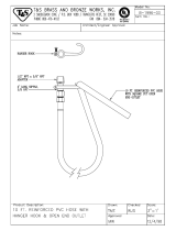
Pressure Relief Valve 26
Condensate Disposal Disposal of Condensate 27
Condensate Drain & Cleaning 28
Gas Piping Gas Piping Guideline 29
Gas Supply Pressure 30
Gas Piping Sizing Chart 31
Gas Pressure Testing Measuring Inlet Gas Pressure 32
Venting Warning 34
Venting Guideline 35
Contaminated Make-up Air Will Damage the Unit 36
Exhaust Pipe Materials 36
Venting Clearances 37
Allowable Vent Lengths 38
Vent Configuration Options 40
Concentric Vent Termination 42
Outdoor Installation 43
Pressure Reducing Valve 45
Outdoor Temp. Sensor Outdoor Temp. Sensor Installation 47
Outdoor Temp. Sensor Installation Guideline 47
K-Factor 48
Electrical Connection 49
Remote Controller
Installation
50
PCB Board Setting 51
Cascade Connection and
Set-up Procedure 52
DIP Switch Setting 57
Installation Checklist 60
Maintenance 64
Factory Setting of
Dip Switch 65
Completing the Install 66
Wiring Diagram 66
Ladder Diagram 67
Wiring Information 68
Components Diagram &
Parts List 70
Service 79

Description
Qty
Navien
Condensing
Combination
Water Heater /
Heating Boiler
1
Remote Controller
1
Owner’s and
Installation
Manual
1
Wall Mounting
Bracket
1
Condensate Drain
Hose
1
Tapping Screws &
Anchors
4
Vent terminators
2
Wall Flanges
4
Pressure
Reducing Valve
Kit
2+1
Accessories:
Check that you have received all of the above parts before installing the
Combination Water Heater / Heating Boiler.
Included with the Combination Water Heater / Heating Boiler:
Item
3


Specifications:
5
Item CH-180 CH-210 CH-240
Heat Capacity (Input)
Flow Rate (DHW)
Efficiency AFUE
Dimensions
Weight
Installation Type
Venting Type
Ignition
Water Pressure (min-max)
Gas Supply Pressure (from source; min-max)
180 Manifold Gas Pressure (min-max)
210 Manifold Gas Pressure (min-max)
240 Manifold Gas Pressure (min-max)
Minimum Flow Rate
Connection
Sizes
S/Heating Supply/
S/Heating Return
DHW Cold Water Inlet/
DHW How Water Supply
Maximum Power
Consumption
NG: 3.75" WC ~ 10.5" WC
NG: 0.4" WC ~ 3.7" WC
NG: 0.4" WC ~ 3.0" WC
NG: 0.6" WC ~ 4.0" WC
LP : 10.5” WC ~ 13.5” WC
LP : 0.8” WC ~ 7.3” WC
LP : 0.8” WC ~ 5.3” WC
LP : 1.0” WC ~ 7.0” WC
Natural Gas
Min: 17,000 Btuh
Max: 150,000 Btuh
Min: 20,000 Btuh
Max: 175,000 Btuh
Min: 20,000 Btuh
Max: 199,000 Btuh
35°F Rise 8.3 GPM
6.5 GPM
3.8 GPM
W17" x H28"x D12"
74 lbs
91%
90.5%
10.0 GPM
7.7 GPM
4.6 GPM
W17" x H28"x D12"
84 lbs
91%
90.2%
11.0 GPM
8.6 GPM
5.1 GPM
W17" x H28" x D12"
84 lbs
91%
90.8%
45°F Rise
NG
Propane
77°F Rise
Indoor/Outdoor Wall-Hung
Forced Draft Direct Vent
Electronic Ignition
15 – 150 PSI
0.5 GPM
1" NPT
3/4" NPT
Auto Feeder 1/2” NPT
3/4" NPT
120VAC, 60Hz
Gas Inlet
Power Supply
Materials
Main Supply
200W (max 2A)
Casing Cold Rolled Carbon Steel
Heat Exchangers
Primary Heat Exchanger: Stainless Steel
Secondary Heat Exchanger: Stainless Steel
Domestic water Heat Exchanger: Stainless Steel
ø3" PVC, ø3" Special Gas Vent Type BH (Class II (PVC)
and Class I (Stainless Steel))
PVC, Flex Aluminum, Flex Stainless Steel, ABS,
0" to combustibles
Venting
Exhaust (ø3")
Intake (ø3")
Vent Clearances
Safety Devices
Flame Rod, Thermal Fuse(Overheat Cut Off device)
APS, GPS, Gas-Valve Operation Detector,
Ignition Operation Detector, Water Temperature High Limit Switch,
Exhaust Temperature High Limit Switch
Plumb Easy Valve Set, Venting Kit, Condensate Neutralizer
Accessories

Key Components: CH
6
NAVIEN Combination Water Heater / Heating Boiler
X
Y
Z
^
[
]
_ ` XW XX XY
\
Y] Y\
Y[
YX
YY
X_
X`
YW
X^
XZ
X[
X]
YZ
X\
1
2
3
4
5
6
7
8
9
10
11
12
13
Intake Air Duct
Fan Motor
WPS
DHW Heat Exchanger
S/H Strainer
Motorized 3-Way Valve
Circulation Pump
S/H Supply Adaptor
S/H Return Adaptor
PCB Board
DHW Cold Water Inlet
Adapter
Auto Feeder Valve
Main Gas Valve
DHW Flow Sensor
Syphon
Transformer
Gas Pressure Sensor
Gas Pipe
Secondary Heat
Exchanger
Primary Heat Exchanger
APS Venturi
Burner
Ignition Transformer
Air Pressure Sensor
Exhaust Duct
Exhaust Pipe
AASS9EXFS002A
BH2501442C
BH1205011C
NASS9EXGPS01
BH2546021A
-
-
BH2501413A
PABNCW48KDN_002
BH1201045A
NASS9EX00009
BH2544007D
BH2505401B
BH2505400B
NAFA9GSFB002
BH2507535A
PAS40KHE_003
BH1301020C
AAVC9EX00009A
NAPU9GLPCT10
BH2507551A
BH2507551A
NACR1GS32301
BH2507560C
BH0904011A
BH0901018A
14
15
16
17
18
19
20
21
22
23
24
25
26
No Description Navien Part No. No Description Navien Part No.

Dimensions: CH Models
7
~h{ly
wylzz|yl
Description
A
B
C
D
E
F
G
H
3"
3"
1"
1"
3/4"
3/4"
1/2"
3/4"
Diameter
Exhaust Pipe
Intake Air Duct
Space Heating
Supply Connection
Space Heating
Return Connection
DHW Supply
Connection
DHW Cold Water
Inlet Connection
Auto Feeder
Connection
Gas Inlet
Connection
%
$
&
' (
)
#
"

Read all safety warnings in the “User’s Operation Manual”. The additional safety issues
outlined below must also be followed completely when installing this Navien Combination
Water Heater / Heating Boiler.
All applicable local, state, national and provincial codes, ordinanes, regulations and laws.
For installations in Messachusetts – code requires the boiler to be installed by a licensed plumb-
ing or gas fitter.
The National Fuel Gas Code NFPA 54/ ANSI Z223.1
National Electric Code ANSI/NFPA 70.
For Installations in Canada – “Installation Code for Gas Burning Eqiupment” CGA/B 149.1 or
B149.2 Canadian Electrical Code Part 1 CSA C22.1
Standard for Controls and satety devices for automatically fired boilers, ANSI/ASME CSD-1,
when requred.
The installation must conform to the requirements of the authority having jurisdiction or, in the
absence of such requirements, to the National Fuel Gas Code, ANSI Z223.1/NFPA 54 and/or
CAN/CSA B149.1, Natural Gas and Propane Installation Code.
This unit is designed for indoor/outdoor installations. DO NOT operate this unit without the vent
piping connected. Exhaust gases must be completely expelled out of the building.
DO NOT use this appliance if any part has been underwater. Immediately call a qualified service
technician to inspect the appliance and replace any part of the control system and any gas control
which has been underwater.
Be sure not to reverse the water and gas connections as this may damage the gas valves.
Water temperature over 125°F can cause severe burns instantly or death from scalding. If the
proposed Water Heater / Heating Boiler outlet temperature is above 125°F, a thermostatically
controlled mixing valve (or a temperature limiting valve) for reducing point of use water tempera-
ture is recommended to reduce the risk of scald injury. Contact a licensed plumber or the local
plumbing authority for further information.
The appliance should be located in an area where leakage within the unit or at its connections will
not result in damage to the surrounding area. Navien will not be responsible for any damage
resulting from leaking if adequate drainage is not provided.
DO NOT use this combination Water Heater / Heating Boiler for any purpose other than water
heating and space heating.
If the water quality is known to be highly acidic and/or extremely hard, water treatments (i.e water
softners) are recommended to maintain full warranty. Consult the local water authority.
8.
9.
10.
11.
12.
13.
14.
1.
2.
3.
4.
5.
6.
7.
Installation Warnings:
8

Protect against snow accumulation around the vent terminations. Ensure the exhaust pipe
and the intake air pipe remain clear from obstructions at all times.
DO NOT overtighten fittings as pipe and/or fitting damage may occur causing leakage.
DO NOT install the combination Water Heater / Heating Boiler where subject to vibrations.
The vent for this appliance shall not terminate over public walkways, or near soffit vents, crawl
space vents and other areas where condensate or vapor could create a nuisance, hazard or
cause property damage. Or where condensate and vapor could cause damage to or could be
detrimental to the operation of regulators, relief valves, or other equipment.
For other than a direct vent appliance, the appliance must be located as close as possible to a
chimney or gas vent.
Should overheating occur or the gas supply fails to shut off, turn off the manual gas control
valve to the appliance. Contact a Service Technician immediately.
The gas connections and water connections must be leak tested before placing into operation.
After placing into operation the ignition safety device must be tested.
Visually inspect the venting system for proper size and horizontal pitch and determine there is
not blockage or restriction, leakage, corrosion and other deficiencies which could cause an
unsafe condition.
Insofar as is practical, close all building doors and windows and all doors between the space
in which the appliances remaining connected to the common venting system are located and
other space of the building. Turn on cloths dryers and any appliance not connected to the
common venting system. Turn on any exhaust fans, such ar range hoods and bathroom
exhausts, so they will operate at maximum speed. Do not operate a summer exhaust fan.
Close fireplace dampers.
Place in operation the appliance being inspected. Follow the lighting instructions. Adjust
thermostat so appliance will operate continuously.
After it has been determined that each appliance remaining connected to the common venting
system properly vents when tested as outlined above, return doors, windows, exhaust fans,
fireplace dampers and any other gas-burning appliance to their pervious condition of use.
Any improper operation of the common venting system should be corrected so the installation
conforms with the National Fuel Gas Code, ANSI Z223.1/NFPA 54 and/or CAN/CSA B149.1,
Natural Gas and Propane Installation Code. When resizing any portion of the common venting
system, the common venting system should be resized to approach the minimum size as
determined using the appropriate tables in Appendix F in the National Fuel Gas Code, ANSI
Z223.1/NFPA 54 and/or CAN/CSA B149.1, Natural Gas and Propane Installation Codes.
The instructions for the installation of the venting system shall specify that the horizontal
portions of the venting system shall be supported to prevent sagging; the methods of and
intervals for support shall be specified. These instructions shall also specify that the venting
system:
■
For Category I, II and IV boilers, have horizontal runs slopping upwards not less than 1/4
inch per foot (21 mm/m) from the boiler to the vent terminal;
■
For Category II and IV boilers, be installed so as to prevent accumulation of condensate;
and
■
For Category II and IV boilers, where necessary, have means provided for drainage of
condensate.
“Caution: Label all wires prior to disconnection when servicing controls. Wiring errors can
cause improper and dangerous operation.”
“Verify proper operation after operation servicing.”
15.
16.
17.
18.
19.
20.
21.
22.
23.
24.
25.
26.
27.
28.
29.
30.
Installation Warnings:
9

Navien units come from the factory configured for use with either Liquid Propane (LP) or
Natural Gas (NG). Before starting the installation, check the rating plate (side of unit) of
the combination Water Heater / Heating Boiler to ensure the unit matches gas type, gas
pressure, water pressure and electrical supply. If the unit does not match the following
requirements, Do Not Install;
Use only the gas type indicated on the
rating plate of the Navien Combination
Water Heater / Heating Boiler. Using a
different gas type will cause abnormal
combustion and Water Heater / Heating
Boiler malfunction.
Getting Started:
10

Check Rating Plate:
11
Automatic Instantaneous Combination Water Heater / Heating Boiler
*Chauffe-eau automatique instantané
Navien America Inc.
20 Goodyear Irvine CA 92618 USA
Tel: (949) 420 – 0420
DO NOT install the unit in a location where there is
excessive high humidity such as a bathroom, damp
crawl space and other areas such as this. This may
cause the unit to malfunction.
To avoid possible electrical shock, DO NOT touch the
internal components of the combination Water Heater /
Heating Boiler or the power plug with wet hands;
DO NOT splash excessive water on the combination
Water Heater / Heating Boiler or remote controller when
cleaning; they are water resistant, not water proof;
AC *c.a. 120 Volts 60Hz Use less than 2 Amp, *Utilise moins de 2A
150 Psi *lb/po2 ANSI Z21. 10. 3b – CSA 4.3B-2004, Z21.13 – CSA 4.9
DO NOT install the Navien Combination Water Heater / Heating Boiler in areas with
excessive high humidity:

Locating the Combination Water Heater /
Heating Boiler:
Location selection may not necessarily affect the operation of the Navien
Combination Water Heater / Heating Boiler but it will affect the customer’s
experience and level of satisfaction with the product. Understanding that each
building is different, the contractor will have to select the best location based on
a combination of the following factors:
Locate the Navien Combination Water Heater / Heating Boiler close to a drain where
condensed water and possible water leakage will not do damage to surrounding areas.
A significant amount of condensed water will be produced each time the combination
Water Heater / Heating Boiler is used. In addition, as with any water heating appliance,
the potential for leakage at some time in the life of the product does exist. If there is no
drain, Navien will not be responsible for any water damage that may occur.
Locate where the city water supply comes into the building.
Locate where the gas supply comes into the building.
Locate the main fixtures in the home (bathrooms, kitchen, laundry, etc.). Select a
location that minimizes the water piping distance between the major fixtures.
Consider venting options: Select a location that minimizes the amount of venting
required. Consider, 4 feet venting restrictions from windows, doors, air intakes,
gas meters, neighbor’s house, etc.
Maintain proper clearances from any openings in the building (see chart in
venting section).
Navien combination Water Heater / Heating Boiler requires a minimum
clearance of 12 inches above the exterior grade.
Do not install the Water Heater / Heating Boiler where moisture from the
exhaust may cause discoloration or damage to walls.
Install the exhaust vent so that there are no obstacles around the termination
and so that exhaust cannot accumulate.
Do not enclose the termination.
Do not install the combination Water Heater / Heating Boiler near vents for
heating or cooling. A minimum distance of 4 feet (1.2m) should be maintained.
It is not recommended to install the combination Water Heater / Heating Boiler
in bathrooms, bedrooms, any occupied rooms normally kept closed, or in indoor
areas without proper venting.
This water heater/boiler must not be installed over carpeting.
Select a location that ensures the Water Heater / Heating Boiler will have sufficient
and clean, combustion air; avoid installation where dust or debris will accumulate;
avoid installation where chemical agents (e.g., hair spray, spray detergent,
chlorine, chemicals) are used.
12
WARNING
Considering the Location “ in accordance to ANSI Z223.1/
NFPA 54 and/or CAN/CSA B149.1 Gas Installation Code”
1.
2.
3.
4.
5.
6.
7.

If installing into a very tight space or corner, please ensure there is sufficient service
and maintenance access to all gas and water piping to ensure that regular
maintenance (such as cleaning the water filter, the air filter and the condensate trap)
will not become problematic.
Allow sufficient clearance:
DO NOT install in an area that contains or stores gasoline or other flammables.
Ensure that combustibles are clear of the immediate area. Ensure hanging laundry or
other such items will not impede the air movement into or out of the Water Heater /
Heating Boiler or its venting.
For commercial applications, avoid greasy fumes or a large amount of steam; take
measures to prevent the fumes and steam from entering in the equipment.
The boiler piping system of a hot water boiler connected to heating coils located in air
handling units where they may be exposed to refigerated air circulation must be
equipped with flow control valves or other automatic means to prevent gravity circula-
tion of the boiler water duriing the cooling cycle.
All Navien units come with an upper mounting bracket pre-drilled at 16" on center
for easy installation on standard stud walls. Affix the bracket to the wall securely,
ensuring that it is level and that it can support the weight of the combination Water
Heater / Heating Boiler. If the strength of the wall it not sufficient, reinforce the area
to prevent any unsafe situations.
If the framing is not standard, reinforcement of the wall is required or if installing
on an uneven surface, fasten 3/4" plywood to the stud wall and then attach the
mounting brackets to the plywood.
When using the supplied mounting bracket, it creates a 5/8" clearance from the
back of the unit.
The upper bracket is installed on the wall and the combination Water Heater /
Heating Boiler is then hung on the bracket. On the back of the combination Water
Heater / Heating Boiler at each of the top corners, there is a hanger bracket on the
back of the combination Water Heater / Heating Boiler that interlocks with a tabs on
the wall mounting bracket.
Top of Water Heater / Heating Boiler
Back of Water Heater / Heating Boiler
Front of Water Heater / Heating Boiler
Sides of Water Heater / Heating Boiler
Bottom of Water Heater / Heating Boiler
Min. 9 inches
Min. 0.5 inches
Min 4 inches
Min. 3 inches
Min. 12 inches
Indoor Install Outdoor Install
Min. 36 inches
Min. 0.5 inches
Min. 24 inches
Min. 3 inches
Min. 12 inches
Locating the Combination Water Heater /
Heating Boiler:
Mounting the Unit to the Wall:
13
8.
9.
10.
11.
12.


Navien Combination Water Heater / Heating Boiler is equipped with a factory installed pres-
sure sensor type Low Water Cut Off device.
The Mininum operation system pressure allowable with this device is 7 psig.
Check local code if a Low Water Cut Off is requred. If so, determine if this device meets the
requirements of the local codes.
If a separate LWCO device is required by certain local jurisdications or when the Navien
Combination Water Heater / Heating Boiler is installed above the system piping, the folloing
guidelines must be followed:
- The LWCO device must be installed in a tee connection on the Water Heater / Heating Boiler
/supply piping above the Water Heater / Heating Boiler.
A hot water boiler installed above radiation level or as required by the Authority having
jurisdiction, must be provided with a low water cutoff device either as a part of the boiler or
at the time of boiler installation.
Failure to properly pipe Water Heater / Heating Boiler may result in improper operation
and damage to the Combination Water Heater / Heating Boiler or structure.
This Combination Water Heater / Heating Boiler must only be used with the following
water supply system conditions;
15
Plumbing:

Plumbing:
16
Do not install automatic air vents on a closed-type expansion tank system. Air must
remain in the system and be returned to the expansion tank to provide an air
cushion.
20 ~ 25
Expansion Tank


/