Page is loading ...

TSync Series
TIMECODEPROCESSOR
with optional GNSS RECEIVER
User Manual
Document Part No: 1226-5000-0050
Revision No.: 3.0
Date: 21-May-2018
spectracom.com


© 2011-2016 Spectracom. All rights reserved.
The information in this document has been carefully reviewed and is
believed to be accurate and up-to-date. Spectracom assumes no respons-
ibility for any errors or omissions that may be contained in this document,
and makes no commitment to keep current the information in this manual, or
to notify any person or organization of updates. This User Manual is sub-
ject to change without notice. For the most current version of this doc-
umentation, please see our web site at spectracom.com.
Spectracom reserves the right to make changes to the product described in
this document at any time and without notice. Any software that may be
provided with the product described in this document is furnished under a
license agreement or nondisclosure agreement. The software may be used
or copied only in accordance with the terms of those agreements.
No part of this publication may be reproduced, stored in a retrieval sys-
tem, or transmitted in any form or any means electronic or mechanical,
including photocopying and recording for any purpose other than the pur-
chaser's personal use without the written permission of Spectracom
Other products and companies referred to herein are trademarks or
registered trademarks of their respective companies or mark holders.
Orolia USA, Inc. dba Spectracom
• 1565 Jefferson Road, Suite 460, Rochester, NY 14623 USA
• 3, Avenue du Canada, 91974 Les Ulis Cedex, France
• Room 208, No. 3 Zhong Guan Village South Road, Hai Dian District, Beijing 100081, China
Do you have questions or comments regarding this User Manual?
è E-mail:
Warranty Information
For a copy of Spectracom's Limited Warranty policy, see the Spectracom
website: http://spectracom.com/support/warranty-information.
User Manual TSync Series I

Blank page.
II User Manual TSync Series

CONTENTS
User Manual TSync Series • TABLE OF CONTENTS
III
CHAPTER 1
Product Overview
1
1.1 Introduction
2
1.2 General Specifications
2
1.3 Power Consumption
4
1.4 Temperature Sensor
4
1.5 Input/Output Specifications
5
1.5.1 Inputs
5
1.5.1.1 1PPS Input
5
1.5.1.2 IRIG AM Input
5
1.5.1.3 IRIG DCLS Input
5
1.5.1.4 GPIO Inputs
6
1.5.2 Outputs
6
1.5.2.1 1PPS Output
6
1.5.2.2 10 MHz Output
6
1.5.2.3 IRIG AM Output
7
1.5.2.4 IRIG DCLS Output
8
1.5.2.5 GPIO Outputs
8
1.6 GNSS Receiver Specifications
9
1.6.1 Internal GNSS Receiver
9
1.6.2 External GNSS Receiver
10
1.6.3 SAASM Receiver
11
1.7 PCI-104 Board Dimensions
12
1.8 Environmental Specifications
13
1.9 Compliance
14
CHAPTER 2
Connector Pinouts
15
2.1 Connectors & Pinouts
16
2.2 Timing Connector Pinouts
17
2.3 External Antenna Connector: Pinout
18

CHAPTER 3
Installation
21
3.1 ESD: Best Practices
22
3.2 PCIe: Changing the Bracket
22
3.3 Installing the Card
24
3.3.1 PCIe, cPCI, VPX, PMC: Card Installation
24
3.3.2 PCI-104: Card Installation
25
3.3.3 PCI-104 Configuration (DIP Switch)
26
3.4 Status LEDs
26
3.5 Upgrades
28
CHAPTER 4
Operation
29
4.1 Theory of Operation
30
4.1.1 Introduction to GPS and GNSS
30
4.1.2 Characteristics of Other GNSS Systems
30
4.1.3 Input References
31
4.1.3.1 Built-in References
33
4.1.4 Input Reference Monitor
35
4.1.5 Clock Subsystem
35
4.1.6 Output References
36
4.1.7 General Purpose Input/Output
38
4.1.7.1 Programmable Inputs
38
4.1.7.2 Programmable Outputs
38
4.1.8 Interrupts
39
4.1.8.1 Interrupt Descriptions
39
4.2 Configuration and Operation
40
4.2.1 Configuring the TSync Product
40
4.2.1.1 Interrupts
40
4.2.1.2 Match Time
40
4.2.1.3 Time Stamping
40
4.2.2 Synchronizing a Linux Machine Using NTP
40
4.2.3 Synchronizing a Windows Machine Using NTP
42
4.2.4 Resetting a TSync Card
42
4.2.4.1 About Volatility
42
IV
User Manual TSync Series • TABLE OF CONTENTS

4.2.5 Powering UP/DOWN a GNSS Receiver
42
4.2.6 System Status
42
CHAPTER 5
Options and Accessories
45
5.1 Accessories & Options
46
CHAPTER 6
Driver Support
53
APPENDIX
Appendix
i
7.1 YOUR SAFETY
ii
7.1.1 Spectracom Safety Symbols
ii
7.1.2 About Safety
iii
7.1.3 Your Responsibilities
iii
7.1.4 Other Safety Tips
iii
7.2 Technical Support
iv
7.2.1 Regional Contact
iv
7.3 Return Shipments
v
INDEX
User Manual TSync Series • TABLE OF CONTENTS
V

BLANK PAGE.
VI
User Manual TSync Series • TABLE OF CONTENTS

CHAPTER 1 • User Manual TSync Series
1
CHAPTER 1
Product Overview
The following topics are included in this Chapter:
1.1 Introduction 2
1.2 General Specifications 2
1.3 Power Consumption 4
1.4 Temperature Sensor 4
1.5 Input/Output Specifications 5
1.6 GNSS Receiver Specifications 9
1.7 PCI-104 Board Dimensions 12
1.8 Environmental Specifications 13
1.9 Compliance 14

1.1 Introduction
Spectracom TSync Time Code Processors with internal GNSS receiver are complete bus-level
synchronized time code processing boards that support multiple timing, frequency and event
inputs and outputs. Inputs used as a timing reference can be configured such that the TSync
Time Code Processor automatically switches to the next lower-priority input when the current tim-
ing reference is lost, thus providing uninterrupted service.
The onboard oscillator is capable of providing a 5ns resolution, and is typically disciplined by
and phase-locked to an external timing input.
In the absence of any valid external timing references this 10MHz oscillator, central to the
TSync Time Code Processor timing functions, provides holdover functionality, thus allowing the
TSync Time Code Processor to continue serving time and frequency, until an external reference
becomes available again.
The TSync Time Code Processor generates an IRIG AM and IRIG DCLS output pair, as well as
10MHz sine wave and 1PPS outputs.
The four programmable inputs may be used as event capture inputs, dedicated to your time-tag-
ging applications. Four user-programmable alarm and frequency outputs are provided as well.
Programmable output functions include a periodic pulse or “heartbeat,” square wave, and a
programmable start/stop time “alarm” output.
Key to the TSync Time Code Processor's functionality is the ability to generate interrupts. Using
one of the many available Spectracom driver packages, you may configure your card using
interrupt-driven algorithms to support your custom application.
1.2 General Specifications
Table 1-1:
TSync family: system specifications and options (x = YES; o = NO)
PCIe cPCI VPX PMC PCI-104
Form factor Low-profile PCIe; full-
height mounting
bracket provided
Compact PCI
(cPCI)
Compliant to
PICMG2.0r3.0
100mm x
160mm
(3U card size)
3U VPX form factor
Compliant to VITA-
46
100mm x 160mm
Single-size
CMC
(Common
Mezzanine
Card) 149mm
x 74mm
Compliant
to
PCI-104
spec. r 1.1
Compliant
to
PCI spec. r
2.2
Bus inter-
face
PCIe x1 Universal Sig-
naling Voltage
3.3V/5V
PCIe x1, R1.1
Connectors to VITA
46.0 for P0, P1,
and P2
Universal Sig-
naling Voltage
3.3V/5V
Universal
Signaling
Voltage
3.3V/5V
2
CHAPTER 1 • User Manual TSync Series Rev. 3.0
1.1 Introduction

PCIe cPCI VPX PMC PCI-104
Bus speed Single-Lane (x1)
PCIe; compliant with
PCIe Base Spec.
R1.1
32-bit address
@ 33/66MHz
Single-Lane (x1)
PCIe; compliant
with PCIe Base
Spec. R1.1
32-bit address
@ 33/66MHz
32-bit
address
@
33/66MHz
GNSS tim-
ing module
72-channel receiver with concurrent constellation reception
Conduction
Cooling
O ANSI/VITA
30.1-2002
VITA 46/IEEE
1101.2
ANSI/VITA
20-2001
O
Thermal
frame
(optional)
O Standard thermal frames available.
Component elevations for custom
frame design available upon request.
O O
Onboard
temp.
sensor
O X X X X
Conformal
coating
(optional)
X X X X X
Custom
backpanel
I/O
O X X X O
Weight 122 g 173 g (w/o
thermal frame)
323 g (w/
thermal frame)
179 g (w/o thermal
frame)
329 g (w/ thermal
frame)
88 g 96g
Oscillators:
TCXO X X X X X
OCXO X X X X X
Rugged
OCXO
O X X O O
References:
IRIG/Other X X X X X
Internal
GNSS
X X X X X
External
GNSS
X X O O O
Internal
SAASM
GPS
O X X O O
1.2 General Specifications
CHAPTER 1 • User Manual TSync Series Rev. 3.0
3

1.3 Power Consumption
Table 1-2:
Board power consumptions (typical)
@ V
DC
PCIe cPCI VPX PMC PCI-104
+3.3 V (±5%) 0.7 A 0.7 A Vs2: 0.85A (+5%/-2%) 0.7A 0.7A
+5V (±5%) n/a 1.4 A Vs3: (+5%/-2.5%)
TCXO, OCXO options: 0.4 A
Rugged OCXO option: 0.6 A
[Rugged OCXO: max. (warm-up): 1.4 A]
1.4A 1.4A
+12V (±8%) 0.2 A 0.2 A Vs1: 0.2 A (±5%) 0.2A 0.2A
–12V (±5%) n/a 0.2 A 12V_AUX: -0.2A 0.2A 0.2A
1.4 Temperature Sensor
With the exception of the PCIe model, all TSync boards are equipped with an on-board tem-
perature sensor:
Operating temperature range: -40°C to 85°C (-40°F to 185°F)
Accuracy: ±3°C max.
Update rate: Once per second.
4
CHAPTER 1 • User Manual TSync Series Rev. 3.0
1.3 Power Consumption

1.5 Input/Output Specifications
1.5.1 Inputs
1.5.1.1 1PPS Input
Available through the timing connector, see "Connectors & Pinouts" on page16 for details.
1Hz pulse, rising edge or falling edge active (selectable)
100ns minimum pulse width
Amplitude: 0V to +5.5V input range, +0.8V
VIL
, +2.0V
VIH
Input impedance <150pF capacitive
1.5.1.2 IRIG AM Input
Available through the timing connector, see "Connectors & Pinouts" on page16 for details.
Accepts IRIG formats A, B, G; NASA36; IEEE 1344
Amplitude: 500mV
p-p
to 10V
p-p
Modulation ratio: 2:1minimum, 6:1maximum
Input impedance: 10 kΩ minimum
DC Common Mode Voltage: ±150V
DC
maximum
Input Stability: Better than 100 ppm
1.5.1.3 IRIG DCLS Input
Available through the timing connector, see "Connectors & Pinouts" on page16 for details.
Accepts IRIG formats A, B, G; NASA36; IEEE 1344 pulse width codes (does not accept
Manchester modulated codes)
RS-485 differential input: –7V to +12V common mode voltage input range, 200mV
p-p
differential voltage threshold
Single-ended input:
+1.3V
VIL min
, +2V
VIH max
+1.45V
VIL typ
, +1.85V
VIH typ
1.5 Input/Output Specifications
CHAPTER 1 • User Manual TSync Series Rev. 3.0
5

1.5.1.4 GPIO Inputs
Available through the timing connector, see "Connectors & Pinouts" on page16 for details.
Amplitude: 0V to +5.5V input range, +0.8V
VIL
, +2.0V
VIH
Polarity (selectable): Positive or negative
Input impedance: <150pF capacitive
50ns active pulse width minimum; 50ns minimum between pulses
Repetition rate. More than 10,000 events per second
Resolution: 5 ns
1.5.2 Outputs
1.5.2.1 1PPS Output
Available through the timing connector, see "Connectors & Pinouts" on page16 for details.
1Hz pulse, rising edge or falling edge active (selectable)
40 ns to 900 ms active pulse width (selectable, 200 ms default)
Rise time: <10 ns
Signal level: TTL compatible, 4.3V
min
, base-to-peak into 50Ω
[PCIe only: TTL compatible, 2.2 V minimum, base-to-peak into high impedance]
Accuracy: Positive edge within ±[X] nanoseconds of UTC when locked to a valid 1PPS
input reference (for [X], see table below).
Table 1-3:
1PPS output accuracy
TCXO OCXO
OCXO (Rugged Option, cPCI
& VPX only)
Accuracy to UTC
(1-sigma
locked to GPS)
±50 ns ±50 ns ±25 ns
Holdover
(constant temp after 2 weeks of GNSS lock)
After 4 hours 12 μs 3 μs 1 μs
After 24 hours 450 μs 100 μs 25 μs
1.5.2.2 10 MHz Output
10MHz sine wave output from oscillator
Available through the timing connector, see "Connectors & Pinouts" on page16 for details.
6
CHAPTER 1 • User Manual TSync Series Rev. 3.0
1.5 Input/Output Specifications

Output impedance: 50 Ω nominal
Output load: 50 Ω minimum
Output harmonics: < -40 dBc
Output spurious: < -70 dBc
10 MHz LVDS Clocks via P2 Connector (VPX only)
Four (4) LVDS differential pairs
Impedance: 100 Ω
Duty cycle: 50%
Rise time: <10 ns
Table 1-4:
10MHz output specifications
TCXO OCXO
OCXO
(RuggedOption,
cPCI & VPX only)
Accuracy
(average over 24 hours
when GNSS locked)
1x10
-11
5x10
-12
2x10
-12
Medium term stability
(without CPS after 2 weeks of GNSS
lock)
1x10
-8
/
day
2x10
-9
/
day
5x10
-10
/ day
Phase noise (dBc/Hz
)
@1Hz — –85 —
@10Hz — –113 –120
@100Hz –110 –120 –135
@1KHz –135 –140 –135
@10KHz –140 –150 –145
Signal wave form & levels
+13 dBm ±3dB into 50 Ω, BNC
1.5.2.3 IRIG AM Output
Available through the timing connector, see "Connectors & Pinouts" on page16 for details.
Output formats A, B, E (100Hz, 1kHz), G; NASA36; IEEE 1344
Amplitude:
0.5V
p-p
to 6V
p-p
into 50 Ω, user settable
1V
p-p
to 12V
p-p
into > 600 Ω
Output impedance: 50 Ω nominal
Output load: 50 Ω minimum
1.5 Input/Output Specifications
CHAPTER 1 • User Manual TSync Series Rev. 3.0
7

Modulation ratio: 3:1 nominal
Accuracy: ±2 to 200 microseconds (IRIG-format dependent)
1.5.2.4 IRIG DCLS Output
Available through the timing connector, see "Connectors & Pinouts" on page16 for details.
Outputs formats: A, B, E, G; NASA36; IEEE 1344 pulse width codes (does not generate
Manchester modulated codes)
RS-485 differential signal:
1.8V
max
common mode output voltage (RS-485 compatible)
1.5V
min
to 3.3V max differential output voltage swing
Single-ended amplitude (100 Ω load):
0.5V
VOL
max, +2.5 V
VOH
min (TTL compatible)
1.5.2.5 GPIO Outputs
Available through the timing connector, see "Connectors & Pinouts" on page16 for details.
Periodic Output:
Amplitude: TTL compatible, 4.3V
min
, base-to-peak into 50Ω
[PCIe only: 2.2 V minimum, base-top-peak into high impedance]
Pulse width: 50ns to 999ms active pulse width, in 20ns increments
Period: 100ns min, 60s max, in 20ns increments
Polarity (selectable): Positive or negative
Time-Match/Alarm Output
Amplitude: TTL compatible, 4.3 V minimum, base-to-peak into 50 Ω; 2.2 V minimum,
base-to-peak into high-impedance
Range: 100 days in 5 ns steps
8
CHAPTER 1 • User Manual TSync Series Rev. 3.0
1.5 Input/Output Specifications

1.6 GNSS Receiver Specifications
TSync Time Code Processors are capable of utilizing GPS/GNSS timing signals as an external
reference. To this end, all models can be ordered with either an optional internal GNSS
receiver, or the TSync PCIe and cPCI models can be configured—at the time of purchase—for
use with an external GNSS receiver (integrated into the antenna housing).
1.6.1 Internal GNSS Receiver
All TSync Time Code Processor models are available with an optional onboard GNSS receiver
(to be ordered at the time of purchase; factory retrofits may be possible.)
If installed, the board supplies 5V
DC
through the GNSS receiver to the external antenna via the
coaxial cable (antenna and cable are sold separately).
Alternatively, TSync PCIe and cPCI boards can also be operated with an external GNSS
receiver (i.e., the receiver is built into the antenna housing). In this case, the board supplies
12V
DC
to the receiver/antenna through its data communications cable.
Receiver type:
72-channel receiver with concurrent dual-constellation reception; pre-configured
to receive GPS/QZSS & GLONASS
Supports GPS/QZSS L1 C/A, GLONASS L1, BeiDou B1
Galileo-ready E1 (subject to firmware upgrade)
Acquisition times:
Cold start – GPS & GLONASS: 26 s; GPS & BeiDou: 27 s
Aided cold start – GPS & GLONASS: 2 s; GPS & BeiDou: 3 s
Sensitivity:
Tracking & Nav – GPS & GLONASS: -167 dBm; GPS & BeiDou: -165 dBm
Reacquisition – GPS & GLONASS, GPS & BeiDou: -160 dBm
Timing accuracy, clear sky: ≤ 20 ns
Time-pulse frequency: 0.25 Hz – 10 MHz
Time-pulse jitter: ±11 ns
Time-mark resolution: 21 ns
Integrity reports: RAIM active, phase uncertainty time-pulse rate/duty-cycle.
Antenna Connection
All TSync Time Code Processor equipped with the optional on-board GNSS receiver have a
front panel SMA RF connector, through which the signal from, and the supply power to the
GNSS antenna (sold separately) are provided (supply power: +5V [±10%] @ 30mA max).
The RF antenna cable (sold separately) is connected to the TSync Time Code Processor board
via a short male-SMA-to-Type-N adapter cable (included), made from RG-316 coaxial cable.
1.6 GNSS Receiver Specifications
CHAPTER 1 • User Manual TSync Series Rev. 3.0
9

Note: The provided cable should be used instead of 3rd party adapter, as it incor-
porates a strain relief, protecting the connectors.
1.6.2 External GNSS Receiver
PCIe and cPCI boards can be operated with an
external GNSS receiver, i.e. the receiver is integrated
into the AcutimeGG smart antenna unit.
A high-density DB-15 connector is used to connect the
external antenna (with its built-in GNSS receiver) to the
board. With external receivers, cable lengths up to
90m (300ft.) are possible.
Electrical Characteristics, Board to Receiver Transmission
RS-485 Differential Signal:
+1.5 V to +2V Common Mode Output Voltage
1.5 V min to 3.3 V max Differential Output Voltage Swing
Electrical Characteristics, Receiver to Board Transmission
RS-485 Differential Input:
-7 V to +12 V common mode voltage input range, 200 mV
p-p
differential voltage
threshold
Electrical Characteristics, Receiver Power
50 mA @ 12 V provided to power the antenna
Specifications, external GNSS receiver
Acquisition time:
10
CHAPTER 1 • User Manual TSync Series Rev. 3.0
1.6 GNSS Receiver Specifications

< 4 minutes from a cold start
Re-acquisition time: < 2 sec (90%; current almanac downloaded)
Frequency:
GPS L1 (1575.42 MHz)
GLONASS L1 (1602 MHz)
Satellites tracked: up to 32 simultaneously
Sync to UTC: within ±15 ns to GPS/UTC (1 sigma) (stationary)
Sensitivity: -136 dBm (acquisition), -141 dBm (tracking)
1PPS accuracy (1-sigma): <15 ns (stationary mode), <45 ns (mobile operation)
Accuracy horizontal position: <6 meters (50%) <9 meters (90%)
Accuracy altitude position: <11 meters (50%) <18 meters (90%)
1.6.3 SAASM Receiver
cPCI and VPX boards are compatible with a SAASM receiver for authorized users. Instructions
specific to SAASM operation are provided in a separate manual. The SAASM receiver is not
compatible with GLONASS.
Receiver type: MPE-S Type II GB-GRAM
Frequency: L1 (1575.42 MHz) and L2 (1227.6 MHz) simultaneous; L1- C/A, P(Y); L2 - P(Y)
Satellite Tracking: 1 to 12
TTFF – Time to First Fix (Synchronization Time):
Cold Start (with almanac download): 15 minutes
Cold Start (no almanac download): 5 minutes
Warm Start: 90 seconds
Hot Start: 10 seconds
TTSF – Time to Subsequent Fix (Reacquisition Time):
< 20 seconds, Off or Stby < 15 minutes
< 25 seconds, Off or Stby < 60 minutes
< 70 seconds, Off < 60 minutes
Antenna connector:
Convection Cooled: SMA Jack (+3.3 V @ 9 mA to 60 mA)
Conduction Cooled: SMB Jack (+3.3 V @ 9 mA to 60 mA)
1PPS accuracy: ±100 ns
Key fill: DS102 standard, DS101 optional
Backup Battery: SAASM I/O connector or P1-VBAT, VPX P1 connector.
1.6 GNSS Receiver Specifications
CHAPTER 1 • User Manual TSync Series Rev. 3.0
11

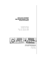
1.7 PCI-104 Board Dimensions
Figure 1-1: Board layout and dimensions
12
CHAPTER 1 • User Manual TSync Series Rev. 3.0
1.7 PCI-104 Board Dimensions
/