
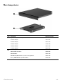
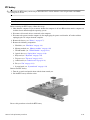
HP Compaq 2230s Notebook PC
Maintenance and Service Guide
Document Part Number: 482392-002
November 2008
This guide is a troubleshooting reference used for maintaining and servicing the computer. It provides
comprehensive information on identifying computer features, components, and spare parts; troubleshooting
computer problems; and performing computer disassembly procedures.

© Copyright 2008 Hewlett-Packard Development Company, L.P.
Bluetooth is a trademark owned by its proprietor and used by Hewlett-Packard Company under license. Intel, Core, and Celeron are
trademarks of Intel Corporation in the U.S. and other countries. Microsoft, Windows, and Windows Vista are U.S. registered trademarks
of Microsoft Corporation. SD Logo is a trademark of its proprietor.
The information contained herein is subject to change without notice. The only warranties for HP products and services are set forth in
the express warranty statements accompanying such products and services. Nothing herein should be construed as constituting an
additional warranty. HP shall not be liable for technical or editorial errors or omissions contained herein.
Second Edition: November 2008
First Edition: August 2008
Document Part Number: 482392-002

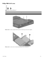
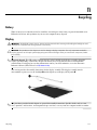
Safety warning notice
Å
WARNING: To reduce the possibility of heat-related injuries or of overheating the computer, do not place the computer directly
on your lap or obstruct the computer air vents. Use the computer only on a hard, flat surface. Do not allow another hard surface,
such as an adjoining optional printer, or a soft surface, such as pillows or rugs or clothing, to block airflow. Also, do not allow
the AC adapter to contact the skin or a soft surface, such as pillows or rugs or clothing, during operation. The computer and the
AC adapter comply with the user-accessible surface temperature limits defined by the International Standard for Safety of
Information Technology Equipment (IEC 60950).

Contents iv
Contents
1 Product description
2 External component identification
Display components . . . . . . . . . . . . . . . . . . . . . . . . . . . . . . . . . . . . . . . . . . . . . . . . . . . . . . . . . . . . . . . . . . . 2–1
Top components . . . . . . . . . . . . . . . . . . . . . . . . . . . . . . . . . . . . . . . . . . . . . . . . . . . . . . . . . . . . . . . . . . . . . . 2–2
Pointing devices . . . . . . . . . . . . . . . . . . . . . . . . . . . . . . . . . . . . . . . . . . . . . . . . . . . . . . . . . . . . . . . . . . 2–2
Buttons and fingerprint reader . . . . . . . . . . . . . . . . . . . . . . . . . . . . . . . . . . . . . . . . . . . . . . . . . . . . . . . 2–3
Keys . . . . . . . . . . . . . . . . . . . . . . . . . . . . . . . . . . . . . . . . . . . . . . . . . . . . . . . . . . . . . . . . . . . . . . . . . . . 2–5
Lights . . . . . . . . . . . . . . . . . . . . . . . . . . . . . . . . . . . . . . . . . . . . . . . . . . . . . . . . . . . . . . . . . . . . . . . . . . 2–6
Front components. . . . . . . . . . . . . . . . . . . . . . . . . . . . . . . . . . . . . . . . . . . . . . . . . . . . . . . . . . . . . . . . . . . . . 2–7
Left-side components . . . . . . . . . . . . . . . . . . . . . . . . . . . . . . . . . . . . . . . . . . . . . . . . . . . . . . . . . . . . . . . . . . 2–7
Right-side components. . . . . . . . . . . . . . . . . . . . . . . . . . . . . . . . . . . . . . . . . . . . . . . . . . . . . . . . . . . . . . . . . 2–8
Bottom components . . . . . . . . . . . . . . . . . . . . . . . . . . . . . . . . . . . . . . . . . . . . . . . . . . . . . . . . . . . . . . . . . . . 2–9
3 Illustrated parts catalog
Serial number location . . . . . . . . . . . . . . . . . . . . . . . . . . . . . . . . . . . . . . . . . . . . . . . . . . . . . . . . . . . . . . . . . 3–1
Computer major components . . . . . . . . . . . . . . . . . . . . . . . . . . . . . . . . . . . . . . . . . . . . . . . . . . . . . . . . . . . . 3–2
Cable Kit . . . . . . . . . . . . . . . . . . . . . . . . . . . . . . . . . . . . . . . . . . . . . . . . . . . . . . . . . . . . . . . . . . . . . . . . . . . 3–8
Plastics Kit . . . . . . . . . . . . . . . . . . . . . . . . . . . . . . . . . . . . . . . . . . . . . . . . . . . . . . . . . . . . . . . . . . . . . . . . . . 3–9
Mass storage devices . . . . . . . . . . . . . . . . . . . . . . . . . . . . . . . . . . . . . . . . . . . . . . . . . . . . . . . . . . . . . . . . . 3–10
Miscellaneous parts . . . . . . . . . . . . . . . . . . . . . . . . . . . . . . . . . . . . . . . . . . . . . . . . . . . . . . . . . . . . . . . . . . 3–11
Sequential part number listing . . . . . . . . . . . . . . . . . . . . . . . . . . . . . . . . . . . . . . . . . . . . . . . . . . . . . . . . . . 3–12
4 Removal and replacement procedures
Preliminary replacement requirements . . . . . . . . . . . . . . . . . . . . . . . . . . . . . . . . . . . . . . . . . . . . . . . . . . . . 4–1
Tools required . . . . . . . . . . . . . . . . . . . . . . . . . . . . . . . . . . . . . . . . . . . . . . . . . . . . . . . . . . . . . . . . . . . . 4–1
Service considerations. . . . . . . . . . . . . . . . . . . . . . . . . . . . . . . . . . . . . . . . . . . . . . . . . . . . . . . . . . . . . . 4–1
Grounding guidelines . . . . . . . . . . . . . . . . . . . . . . . . . . . . . . . . . . . . . . . . . . . . . . . . . . . . . . . . . . . . . . 4–2
Unknown user password . . . . . . . . . . . . . . . . . . . . . . . . . . . . . . . . . . . . . . . . . . . . . . . . . . . . . . . . . . . . 4–4
Component replacement procedures . . . . . . . . . . . . . . . . . . . . . . . . . . . . . . . . . . . . . . . . . . . . . . . . . . . . . . 4–5
Serial number . . . . . . . . . . . . . . . . . . . . . . . . . . . . . . . . . . . . . . . . . . . . . . . . . . . . . . . . . . . . . . . . . . . . 4–5
Computer feet . . . . . . . . . . . . . . . . . . . . . . . . . . . . . . . . . . . . . . . . . . . . . . . . . . . . . . . . . . . . . . . . . . . . 4–6
Battery. . . . . . . . . . . . . . . . . . . . . . . . . . . . . . . . . . . . . . . . . . . . . . . . . . . . . . . . . . . . . . . . . . . . . . . . . . 4–7
Hard drive . . . . . . . . . . . . . . . . . . . . . . . . . . . . . . . . . . . . . . . . . . . . . . . . . . . . . . . . . . . . . . . . . . . . . . . 4–8
Memory module . . . . . . . . . . . . . . . . . . . . . . . . . . . . . . . . . . . . . . . . . . . . . . . . . . . . . . . . . . . . . . . . . 4–10
WLAN module . . . . . . . . . . . . . . . . . . . . . . . . . . . . . . . . . . . . . . . . . . . . . . . . . . . . . . . . . . . . . . . . . . 4–12
Optical drive . . . . . . . . . . . . . . . . . . . . . . . . . . . . . . . . . . . . . . . . . . . . . . . . . . . . . . . . . . . . . . . . . . . . 4–16
Keyboard. . . . . . . . . . . . . . . . . . . . . . . . . . . . . . . . . . . . . . . . . . . . . . . . . . . . . . . . . . . . . . . . . . . . . . . 4–18
Top cover . . . . . . . . . . . . . . . . . . . . . . . . . . . . . . . . . . . . . . . . . . . . . . . . . . . . . . . . . . . . . . . . . . . . . . 4–21
Speaker assembly . . . . . . . . . . . . . . . . . . . . . . . . . . . . . . . . . . . . . . . . . . . . . . . . . . . . . . . . . . . . . . . . 4–25
Display assembly . . . . . . . . . . . . . . . . . . . . . . . . . . . . . . . . . . . . . . . . . . . . . . . . . . . . . . . . . . . . . . . . 4–26
Audio board. . . . . . . . . . . . . . . . . . . . . . . . . . . . . . . . . . . . . . . . . . . . . . . . . . . . . . . . . . . . . . . . . . . . . 4–32
Fan. . . . . . . . . . . . . . . . . . . . . . . . . . . . . . . . . . . . . . . . . . . . . . . . . . . . . . . . . . . . . . . . . . . . . . . . . . . . 4–33

Contents v
System board. . . . . . . . . . . . . . . . . . . . . . . . . . . . . . . . . . . . . . . . . . . . . . . . . . . . . . . . . . . . . . . . . . . . 4–34
RTC battery. . . . . . . . . . . . . . . . . . . . . . . . . . . . . . . . . . . . . . . . . . . . . . . . . . . . . . . . . . . . . . . . . . . . . 4–36
Modem module . . . . . . . . . . . . . . . . . . . . . . . . . . . . . . . . . . . . . . . . . . . . . . . . . . . . . . . . . . . . . . . . . . 4–37
Bluetooth module . . . . . . . . . . . . . . . . . . . . . . . . . . . . . . . . . . . . . . . . . . . . . . . . . . . . . . . . . . . . . . . . 4–38
Heat sink . . . . . . . . . . . . . . . . . . . . . . . . . . . . . . . . . . . . . . . . . . . . . . . . . . . . . . . . . . . . . . . . . . . . . . . 4–40
Processor . . . . . . . . . . . . . . . . . . . . . . . . . . . . . . . . . . . . . . . . . . . . . . . . . . . . . . . . . . . . . . . . . . . . . . 4–42
5 Computer Setup
Starting Computer Setup . . . . . . . . . . . . . . . . . . . . . . . . . . . . . . . . . . . . . . . . . . . . . . . . . . . . . . . . . . . . . . . 5–1
Navigating and selecting in Computer Setup. . . . . . . . . . . . . . . . . . . . . . . . . . . . . . . . . . . . . . . . . . . . . . . . 5–1
Restoring factory settings in Computer Setup . . . . . . . . . . . . . . . . . . . . . . . . . . . . . . . . . . . . . . . . . . . . . . . 5–2
Computer Setup menus . . . . . . . . . . . . . . . . . . . . . . . . . . . . . . . . . . . . . . . . . . . . . . . . . . . . . . . . . . . . . . . . 5–2
File menu. . . . . . . . . . . . . . . . . . . . . . . . . . . . . . . . . . . . . . . . . . . . . . . . . . . . . . . . . . . . . . . . . . . . . . . . 5–2
Security menu . . . . . . . . . . . . . . . . . . . . . . . . . . . . . . . . . . . . . . . . . . . . . . . . . . . . . . . . . . . . . . . . . . . . 5–3
Diagnostics menu . . . . . . . . . . . . . . . . . . . . . . . . . . . . . . . . . . . . . . . . . . . . . . . . . . . . . . . . . . . . . . . . . 5–3
System Configuration menu . . . . . . . . . . . . . . . . . . . . . . . . . . . . . . . . . . . . . . . . . . . . . . . . . . . . . . . . . 5–4
6 Specifications
Computer specifications. . . . . . . . . . . . . . . . . . . . . . . . . . . . . . . . . . . . . . . . . . . . . . . . . . . . . . . . . . . . . . . . 6–1
12.1-inch, WXGA display specifications. . . . . . . . . . . . . . . . . . . . . . . . . . . . . . . . . . . . . . . . . . . . . . . . . . . 6–2
Hard drive specifications . . . . . . . . . . . . . . . . . . . . . . . . . . . . . . . . . . . . . . . . . . . . . . . . . . . . . . . . . . . . . . . 6–2
DVD/CD-RW Combo Drive specifications. . . . . . . . . . . . . . . . . . . . . . . . . . . . . . . . . . . . . . . . . . . . . . . . . 6–3
Blu-ray ROM DVD±RW SuperMulti DL Drive specifications . . . . . . . . . . . . . . . . . . . . . . . . . . . . . . . . . 6–3
DVD±RW SuperMulti Double-Layer Drive specifications. . . . . . . . . . . . . . . . . . . . . . . . . . . . . . . . . . . . . 6–4
DVD-ROM Drive. . . . . . . . . . . . . . . . . . . . . . . . . . . . . . . . . . . . . . . . . . . . . . . . . . . . . . . . . . . . . . . . . . . . . 6–4
System DMA specifications. . . . . . . . . . . . . . . . . . . . . . . . . . . . . . . . . . . . . . . . . . . . . . . . . . . . . . . . . . . . . 6–5
System interrupt specifications . . . . . . . . . . . . . . . . . . . . . . . . . . . . . . . . . . . . . . . . . . . . . . . . . . . . . . . . . . 6–5
System I/O address specifications . . . . . . . . . . . . . . . . . . . . . . . . . . . . . . . . . . . . . . . . . . . . . . . . . . . . . . . . 6–6
System memory map specifications. . . . . . . . . . . . . . . . . . . . . . . . . . . . . . . . . . . . . . . . . . . . . . . . . . . . . . . 6–8
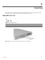
7 Screw listing
Phillips PM1.5×3.0 screw . . . . . . . . . . . . . . . . . . . . . . . . . . . . . . . . . . . . . . . . . . . . . . . . . . . . . . . . . . . . . . 7–1
Phillips PM2.0×3.0 screw . . . . . . . . . . . . . . . . . . . . . . . . . . . . . . . . . . . . . . . . . . . . . . . . . . . . . . . . . . . . . . 7–3
Phillips PM2.0×4.0 screw . . . . . . . . . . . . . . . . . . . . . . . . . . . . . . . . . . . . . . . . . . . . . . . . . . . . . . . . . . . . . . 7–4
Phillips PM2.0×5.0 captive screw . . . . . . . . . . . . . . . . . . . . . . . . . . . . . . . . . . . . . . . . . . . . . . . . . . . . . . . . 7–5
Phillips PM2.0×3.0 screw . . . . . . . . . . . . . . . . . . . . . . . . . . . . . . . . . . . . . . . . . . . . . . . . . . . . . . . . . . . . . . 7–6
Phillips PM2.0×6.0 screw . . . . . . . . . . . . . . . . . . . . . . . . . . . . . . . . . . . . . . . . . . . . . . . . . . . . . . . . . . . . . . 7–7
Phillips PM2.0×5.0 screw . . . . . . . . . . . . . . . . . . . . . . . . . . . . . . . . . . . . . . . . . . . . . . . . . . . . . . . . . . . . . . 7–8
Phillips PM2.0×7.0 captive screw . . . . . . . . . . . . . . . . . . . . . . . . . . . . . . . . . . . . . . . . . . . . . . . . . . . . . . . . 7–9
Phillips PM2.0×10.0 captive screw . . . . . . . . . . . . . . . . . . . . . . . . . . . . . . . . . . . . . . . . . . . . . . . . . . . . . . 7–10
Phillips PM2.5×10.0 captive screw . . . . . . . . . . . . . . . . . . . . . . . . . . . . . . . . . . . . . . . . . . . . . . . . . . . . . . 7–11
Phillips PM3.0×3.0 screw . . . . . . . . . . . . . . . . . . . . . . . . . . . . . . . . . . . . . . . . . . . . . . . . . . . . . . . . . . . . . 7–12
Phillips PM3.0×4.0 screw . . . . . . . . . . . . . . . . . . . . . . . . . . . . . . . . . . . . . . . . . . . . . . . . . . . . . . . . . . . . . 7–13
Phillips T2.0×2.0BH screw . . . . . . . . . . . . . . . . . . . . . . . . . . . . . . . . . . . . . . . . . . . . . . . . . . . . . . . . . . . . 7–14
Torx T8M2.5×6.0 slotted screw. . . . . . . . . . . . . . . . . . . . . . . . . . . . . . . . . . . . . . . . . . . . . . . . . . . . . . . . . 7–15
8 Backup and recovery
Backup and recovery in Windows Vista . . . . . . . . . . . . . . . . . . . . . . . . . . . . . . . . . . . . . . . . . . . . . . . . . . . 8–1
Backup tips . . . . . . . . . . . . . . . . . . . . . . . . . . . . . . . . . . . . . . . . . . . . . . . . . . . . . . . . . . . . . . . . . . . . . . 8–1
Backing up your information . . . . . . . . . . . . . . . . . . . . . . . . . . . . . . . . . . . . . . . . . . . . . . . . . . . . . . . . 8–2
Performing a recovery. . . . . . . . . . . . . . . . . . . . . . . . . . . . . . . . . . . . . . . . . . . . . . . . . . . . . . . . . . . . . . 8–2

Contents vi
Backup and recovery in Windows XP . . . . . . . . . . . . . . . . . . . . . . . . . . . . . . . . . . . . . . . . . . . . . . . . . . . . . 8–4
Backing up your information . . . . . . . . . . . . . . . . . . . . . . . . . . . . . . . . . . . . . . . . . . . . . . . . . . . . . . . . 8–4
Performing a recovery. . . . . . . . . . . . . . . . . . . . . . . . . . . . . . . . . . . . . . . . . . . . . . . . . . . . . . . . . . . . . . 8–5
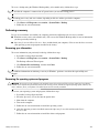
9 Connector pin assignments
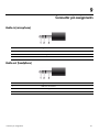
Audio-in (microphone). . . . . . . . . . . . . . . . . . . . . . . . . . . . . . . . . . . . . . . . . . . . . . . . . . . . . . . . . . . . . . . . . 9–1
Audio-out (headphone) . . . . . . . . . . . . . . . . . . . . . . . . . . . . . . . . . . . . . . . . . . . . . . . . . . . . . . . . . . . . . . . . 9–1
External monitor. . . . . . . . . . . . . . . . . . . . . . . . . . . . . . . . . . . . . . . . . . . . . . . . . . . . . . . . . . . . . . . . . . . . . . 9–2
HDMI . . . . . . . . . . . . . . . . . . . . . . . . . . . . . . . . . . . . . . . . . . . . . . . . . . . . . . . . . . . . . . . . . . . . . . . . . . . . . . 9–3
RJ-11 (modem). . . . . . . . . . . . . . . . . . . . . . . . . . . . . . . . . . . . . . . . . . . . . . . . . . . . . . . . . . . . . . . . . . . . . . . 9–4
RJ-45 (network) . . . . . . . . . . . . . . . . . . . . . . . . . . . . . . . . . . . . . . . . . . . . . . . . . . . . . . . . . . . . . . . . . . . . . . 9–4
Universal Serial Bus. . . . . . . . . . . . . . . . . . . . . . . . . . . . . . . . . . . . . . . . . . . . . . . . . . . . . . . . . . . . . . . . . . . 9–5
10Power cord set requirements
Requirements for all countries and regions . . . . . . . . . . . . . . . . . . . . . . . . . . . . . . . . . . . . . . . . . . . . . . . . 10–1
Requirements for specific countries and regions . . . . . . . . . . . . . . . . . . . . . . . . . . . . . . . . . . . . . . . . . . . . 10–2
11Recycling
Battery . . . . . . . . . . . . . . . . . . . . . . . . . . . . . . . . . . . . . . . . . . . . . . . . . . . . . . . . . . . . . . . . . . . . . . . . . . . . 11–1
Display . . . . . . . . . . . . . . . . . . . . . . . . . . . . . . . . . . . . . . . . . . . . . . . . . . . . . . . . . . . . . . . . . . . . . . . . . . . . 11–1
Index

Product description 1–1
1
Product description
Category Description Models with
GL40 system
board
Models with
GM45 system
board
Product name HP Compaq 2230s Notebook PC XX
Processors Intel® Core™2 Duo processors:
■ T9600 2.8-GHz processor, 6-MB L2 cache, 1066-MHz
front side bus (FSB)
X
■ T9400 2.53-GHz processor, 6-MB L2 cache, 1066-MHz
FSB
X
■ P9500 2.53-GHz processor, 6-MB L2 cache, 1066-MHz
FSB
X
■ P8700 2.53-GHz processor, 3-MB L2 cache, 1066-MHz
FSB
X
■ P8600 2.4-GHz, 3-MB L2 cache, 1066-MHz FSB X
■ P8400 2.26-GHz processor, 3-MB L2 cache, 1066-MHz
FSB
X
■ P7370 2.0-GHz processor, 3-MB L2 cache, 1066-MHz
FSB (for use with Intel WLAN only)
X
Intel Core Duo processors:
■ P5870 2.0-GHz processor, 2-MB L2 cache, 800-MHz FSB
(for use with no-WLAN option or Intel WLAN only)
X
■ P5670 1.8-GHz processor, 2-MB L2 cache, 800-MHz FSB
(for use with no-WLAN option or Intel WLAN only)
X
■ T3400 2.16-GHz processor, 1-MB L2 cache,
667-MHz FSB
XX
■ T3200 2.0-GHz processor, 1-MB L2 cache, 667-MHz FSB X X
Intel Celeron®-M processors:
■ 585 2.16-GHz processor, 1-MB L2 cache, 667-MHz FSB X
■ 575 2.0-GHz processor, 1-MB L2 cache, 667-MHz FSB X
Intel Celeron-T processors:
■ T1700 1.83-GHz processor, 1-MB L2 cache,
667-MHz FSB
X
■ T1600 1.66-GHz processor, 1-MB cache, 667-MHz FSB X
Chipset Northbridge: Intel GL40 X
Northbridge: Intel GM45 X
Southbridge: Intel ICH9M X X
(Continued)

Product description 1–2
Graphics Intel Unified Memory Architecture (UMA) graphics
subsystem integrated with shared system memory
(dynamically allocated)
XX
Panel 12.1-inch WXGA panel (1280 × 800) X X
12.1-inch WXGA panel (1280 x 800) with integrated webcam X X
12.1-inch WXGA panel (1280 x 800) with BrightView X X
12.1-inch WXGA panel (1280 x 800) with BrightView and
integrated webcam
XX
All display assemblies include 2 wireless local area network
(WLAN) antennae
Memory 2 customer-accessible/upgradable memory module slots X X
Supports dual-channel memory X X
Supports up to 4 GB of system RAM X X
PC2-6400, 800-MHz, DDR2
Supports the following configurations:
■ 4096-MB total system memory (2048 x 2, dual-channel) X X
■ 3072-MB total system memory (2048 + 1024) X X
■ 2048-MB total system memory (1024 × 2, dual-channel) X X
■ 2048-MB total system memory (2048 × 1) X X
■ 1024-MB total system memory (1024 × 1) X X
Hard drives Supports 9.5-mm, 2.5-inch hard drives X X
Customer-accessible X X
Serial ATA X X
Supports the following drives:
■ 320-GB, 5400-rpm X X
■ 250-GB, 5400-rpm X X
■ 160-GB, 7200-rpm X X
■ 160-GB, 5400-rpm X X
■ 120-GB, 5400-rpm X X
Optical drives Fixed (removal of 1 screw required) X X
Customer-accessible X X
Serial ATA X X
Supports no-optical-drive option X X
Supports the following drives:
■ DVD/CD-RW Combo Drive X X
■ DVD-ROM Drive X X
■ DVD±RW SuperMulti Double-Layer Drive with LightScribe X X
■ Blu-ray ROM DVD±RW SuperMulti DL Drive X
Diskette drive Supports external USB diskette drive only X X
(Continued)
Category Description Models with
GL40 system
board
Models with
GM45 system
board

Product description 1–3
Microphone Integrated mono microphone X X
Audio Azalia audio X X
2 speakers X X
Modem 56K V.92 1.5-inch data/fax modem with digital line guard X X
Modem cable is not included
Ethernet Intel Broadcom 88E8072 10/100/1000 network interface
card (NIC)
XX
Ethernet cable included X X
Wireless Integrated WLAN options by way of wireless module:
2 wireless antennae built into display assembly X X
Supports no-WLAN option X X
Support for the following WLAN formats:
■ Broadcom 802.11a/b/g/n X X
■ Intel 802.11a/b/g/n X X
■ Broadcom 802.11b/g X X
■ Intel 802.11a/b/g X X
Integrated personal area network (PAN) options by way
of Bluetooth® module:
Support for no-WPAN option X X
Broadcom Bluetooth X X
External media card One ExpressCard slot, supporting optional ExpressCard/34
cards
XX
Media Card Reader supporting MMC, SD, and SD High
Capacity digital cards
XX
Ports Audio-in (mono microphone) X X
Audio-out (stereo headphone) X X
HDMI X X
RJ-11 (modem) X X
RJ-45 (Ethernet, includes link and activity lights) X X
USB (3) X X
VGA (Dsub 15-pin) supporting 1600 × 1200 external
resolution at 75 GHz (hot plug/unplug with auto-detect)
XX
Multi-pin AC power X X
Docking None X X
Keyboard/pointing
devices
Spill-resistant full-size keyboard X X
TouchPad with 2 TouchPad buttons X X
Supports 2-way scroll X X
Taps enabled as default X X
Windows Vista® Hardware Start Button X X
(Continued)
Category Description Models with
GL40 system
board
Models with
GM45 system
board

Product description 1–4
Power requirements 65-W AC adapter with localized and pointing stick cable plug
support (3-wire plug with ground pin, supports 3-pin DC
connector)
XX
4-cell, 37-Wh Li-ion battery X X
8-cell, 73-Wh Li-ion battery X X
Security Security cable slot X X
Operating system Preinstalled:
Windows Vista® Home Basic 32 X X
Windows Vista Home Premium 32 X X
Windows Vista Business 32 X X
Windows Vista Business (with downgrade to Windows® XP
Professional)
XX
FreeDOS X X
Red Flag Linux X X
Serviceability End-user replaceable parts:
AC adapter X X
Battery (system) X X
Hard drive X X
Memory module X X
Optical drive X X
WLAN module X X
Category Description Models with
GL40 system
board
Models with
GM45 system
board

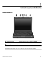
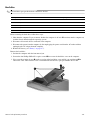
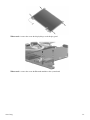
External component identification 2–1
2
External component identification
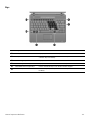
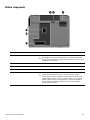
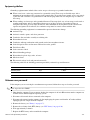
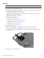
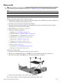
Display components
Item Component Function
1
Wireless antennae (2)* Send and receive wireless signals to communicate with WLANs.
2
Internal microphones (2) Record sound.
3
Webcam light (select models only) On: The webcam is in use.
4
Webcam (select models only) Records audio and video and captures still photographs.
*The antennae are not visible from the outside of the computer. For optimal transmission, keep the areas immediately around
the antennae free from obstructions. To see wireless regulatory notices, refer to the section of the
Regulatory, Safety and
Environmental Notices
that applies to your country or region. These notices are located in Help and Support.

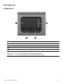
External component identification 2–2
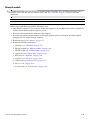
Top components
Pointing devices
Item Component Function
1
TouchPad* Moves the pointer and selects or activates items on the screen.
2
Left TouchPad button* Functions like the left button on an external mouse.
3
Right TouchPad button* Functions like the right button on an external mouse.
4
Vertical scroll zone Scrolls up or down.
*This table describes factory settings. View or change device preferences as follows:
■ In Windows Vista, select Start > Control Panel > Hardware and Sound > Mouse.
■ In Windows XP, select Start > Control Panel > Printers and Other Hardware > Mouse.

External component identification 2–3
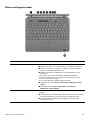
Buttons and fingerprint reader
Item Component Function
1
Power button ■ When the computer is off, press the button to turn on the computer.
■ When the computer is on, press the button to shut down the computer.
■ When the computer is in Standby or the Sleep state, press the button
briefly to exit Standby or the Sleep state.
■ When the computer is in Hibernation, press the button briefly to exit
Hibernation.
If the computer has stopped responding and Windows® shutdown
procedures are ineffective, press and hold the power button for at least
5 seconds to turn off the computer.
To learn more about power settings, follow these steps:
■ In Windows Vista, select Start > Control Panel > Mobile PC > Power
Options.
■ In Windows XP, select Start > Control Panel > System and
Maintenance > Power Options.
2
Info button Launches Info Center, which provides shortcuts, such as the
following:
■ HP 3D DriveGuard—Controls settings for software that protects the hard
drive by parking the drive when the computer is dropped or moved.
■ HP Software Setup—Installs preloaded applications to make them
accessible to the user.
(Continued)

External component identification 2–4
3
Presentation button Opens the Presentation Options window, where you can start a frequently
used presentation, file, program, or Web site. You can also adjust display
setting for optimum viewing.
4
Wireless button Turns the wireless feature on or off, but does not establish a wireless
connection.
✎
You must set up or access a wireless network to establish a wireless
connection.
5
Volume mute button Mutes and restores speaker sound.
6
Volume down button Decreases speaker volume.
7
Volume scroll zone Adjusts speaker volume. Slide your finger to the left to decrease volume and
to the right to increase volume.
8
Volume up button Increases speaker volume.
9
Fingerprint reader Allows a fingerprint logon to Windows, instead of a password logon.
Item Component Function

External component identification 2–5
Keys
Item Component Function
1
esc key Displays system information when pressed in combination with the fn key.
2
fn key Executes frequently used system functions when pressed in combination with
a function key or the esc key.
3
Windows logo key Displays the Windows Start menu.
4
Windows applications key Displays a shortcut menu for items beneath the pointer.
5
Embedded numeric keypad keys Can be used like the keys on an external numeric keypad.
6
Function keys Execute frequently used system functions when pressed in combination with
the fn key.

External component identification 2–6
Lights
Item Component Function
1
Caps lock light On: Caps lock is on.
2
Battery light (beside power connector) ■ Amber: A battery is charging.
■ Green: A battery is close to full charge capacity.
■ Blinking amber: A battery that is the only available power source has
reached a low battery level. When the battery reaches a critical battery
level, the battery light begins blinking rapidly.
■ Off: If the computer is plugged into an external power source, the light turns
off when all batteries in the computer are fully charged. If the computer is
not plugged into an external power source, the light stays off until the
battery reaches a low battery level.
3
Power light ■ On: The computer is on.
■ Blinking: The computer is in the Sleep state.
■ Blinking rapidly: An AC adapter with a higher power rating should be
connected.
■ Off: The computer is off or in Hibernation.
4
Info button light ■ On: The Info Center is launched.
5
Presentation button light ■ On: Presentation Options is on.
6
Wireless light ■ Blue: An integrated wireless device, such as a wireless local area network
(WLAN) device, an HP Mobile Broadband Module, and/or a Bluetooth®
device, is on.
■ Amber: All wireless devices are off.
7
Volume mute light ■ Off: Computer sound is on.
■ On: Computer sound is off.
8
Volume down light Blinking: The volume scroll zone is being used to decrease speaker volume.
9
Volume up Blinking: The volume scroll zone is being used to increase speaker volume.

External component identification 2–7
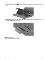
Front components
Left-side components
Item Component Function
1
Drive light ■ Blinking green: The hard drive or optical drive is being accessed.
■ Amber (select models only): HP 3D DriveGuard has temporarily parked the
hard drive.
2
Audio-in (microphone) jack Connects an optional computer headset microphone, stereo array
microphone, or monaural microphone.
3
Audio-out (headphone) jack Produces sound when connected to optional powered stereo speakers,
headphones, ear buds, a headset, or television audio.
Item Component Function
1
Battery light ■ Amber: A battery is charging.
■ Turquoise: A battery is close to full charge capacity.
■ Blinking amber: A battery that is the only available power source has
reached a low battery level. When the battery reaches a critical battery
level, the battery light begins blinking rapidly.
■ Off: If the computer is plugged into an external power source, the light turns
off when all batteries in the computer are fully charged. If the computer is
not plugged into an external power source, the light stays off until the
battery reaches a low battery level.
2
Power connector Connects an AC adapter.
3
RJ-45 (network) jack Connects a network cable.
4
RJ-11 (modem) jack Connects a modem cable.
5
USB port Connects an optional USB device.
6
Optical drive Reads optical discs and, on select models, also writes to optical discs.

External component identification 2–8
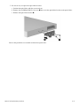
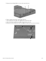
Right-side components
Item Component Function
1
ExpressCard slot Supports optional ExpressCard/34 cards.
2
Memory Card Reader
(select models only)
Supports the following optional digital card formats:
■ MultiMediaCard
■ MultiMediaCard Plus
■ Secure Digital Memory Card
■ Secure Digital High Capacity Memory Card
3
HDMI port (select models only) Connects an optional video or audio device, such as a high-definition
television or any compatible digital or audio component.
4
USB ports (2) Connects an optional USB device.
5
External monitor port Connects an external VGA monitor or projector.
6
Vent Enables airflow to cool internal components.
✎
The computer fan starts up automatically to cool internal components
and prevent overheating. It is normal for the internal fan to cycle on and
off during routine operation.
7
Security cable slot Attaches an optional security cable to the computer.
✎
The security cable is designed to act as a deterrent, but it may not
prevent the computer from being mishandled or stolen.

External component identification 2–9
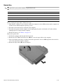
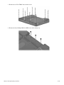
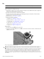
Bottom components
Item Component Function
1
Vents (3) Enables airflow to cool internal components.
✎
The computer fan starts up automatically to cool internal components
and prevent overheating. It is normal for the internal fan to cycle on and
off during routine operation.
2
Hard drive bay Holds the hard drive and two memory module slots.
3
Battery bay Holds the battery.
4
Battery release latch Releases the battery from the battery bay.
5
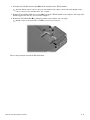
Wireless module compartment Contains a WLAN module slot.
Ä
To prevent an unresponsive system, use only a wireless module
authorized for use in the computer by the governmental agency that
regulates wireless devices in your country or region. If you install the
module and then receive a warning message, remove the module to
restore computer functionality, and then contact technical support
through Help and Support.

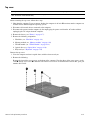
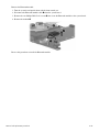
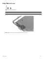
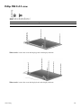
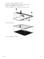
Illustrated parts catalog 3–1
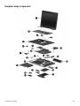
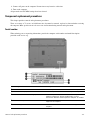
3
Illustrated parts catalog
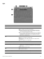
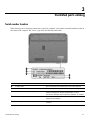
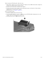
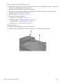
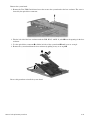
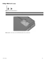
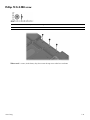
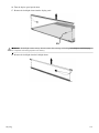
Serial number location
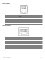
When ordering parts or requesting information, provide the computer serial number and model number located on
the bottom of the computer. The service tag provides the following information.
Item Component Description
1 Product name This is the product name affixed to the front of the computer.
2 Serial number (s/n) This is an alphanumeric identifier that is unique to each product.
3 Part number/Product number (p/n) This number provides specific information about the product's
hardware components. The part number helps a service
technician to determine what components and parts are needed.
4 Model description This is the number used to locate documents, drivers, and
support for the computer.
5 Warranty period This number describes the duration of the warranty period for the
computer.
Page is loading ...
Page is loading ...
Page is loading ...
Page is loading ...
Page is loading ...
Page is loading ...
Page is loading ...
Page is loading ...
Page is loading ...
Page is loading ...
Page is loading ...
Page is loading ...
Page is loading ...
Page is loading ...
Page is loading ...
Page is loading ...
Page is loading ...
Page is loading ...
Page is loading ...
Page is loading ...
Page is loading ...
Page is loading ...
Page is loading ...
Page is loading ...
Page is loading ...
Page is loading ...
Page is loading ...
Page is loading ...
Page is loading ...
Page is loading ...
Page is loading ...
Page is loading ...
Page is loading ...
Page is loading ...
Page is loading ...
Page is loading ...
Page is loading ...
Page is loading ...
Page is loading ...
Page is loading ...
Page is loading ...
Page is loading ...
Page is loading ...
Page is loading ...
Page is loading ...
Page is loading ...
Page is loading ...
Page is loading ...
Page is loading ...
Page is loading ...
Page is loading ...
Page is loading ...
Page is loading ...
Page is loading ...
Page is loading ...
Page is loading ...
Page is loading ...
Page is loading ...
Page is loading ...
Page is loading ...
Page is loading ...
Page is loading ...
Page is loading ...
Page is loading ...
Page is loading ...
Page is loading ...
Page is loading ...
Page is loading ...
Page is loading ...
Page is loading ...
Page is loading ...
Page is loading ...
Page is loading ...
Page is loading ...
Page is loading ...
Page is loading ...
Page is loading ...
Page is loading ...
Page is loading ...
Page is loading ...
Page is loading ...
Page is loading ...
Page is loading ...
Page is loading ...
Page is loading ...
Page is loading ...
Page is loading ...
Page is loading ...
Page is loading ...
Page is loading ...
Page is loading ...
Page is loading ...
Page is loading ...
Page is loading ...
Page is loading ...
Page is loading ...
Page is loading ...
Page is loading ...
Page is loading ...
Page is loading ...
Page is loading ...
Page is loading ...
Page is loading ...
Page is loading ...
Page is loading ...
Page is loading ...
Page is loading ...
Page is loading ...
Page is loading ...
Page is loading ...
-
 1
1
-
 2
2
-
 3
3
-
 4
4
-
 5
5
-
 6
6
-
 7
7
-
 8
8
-
 9
9
-
 10
10
-
 11
11
-
 12
12
-
 13
13
-
 14
14
-
 15
15
-
 16
16
-
 17
17
-
 18
18
-
 19
19
-
 20
20
-
 21
21
-
 22
22
-
 23
23
-
 24
24
-
 25
25
-
 26
26
-
 27
27
-
 28
28
-
 29
29
-
 30
30
-
 31
31
-
 32
32
-
 33
33
-
 34
34
-
 35
35
-
 36
36
-
 37
37
-
 38
38
-
 39
39
-
 40
40
-
 41
41
-
 42
42
-
 43
43
-
 44
44
-
 45
45
-
 46
46
-
 47
47
-
 48
48
-
 49
49
-
 50
50
-
 51
51
-
 52
52
-
 53
53
-
 54
54
-
 55
55
-
 56
56
-
 57
57
-
 58
58
-
 59
59
-
 60
60
-
 61
61
-
 62
62
-
 63
63
-
 64
64
-
 65
65
-
 66
66
-
 67
67
-
 68
68
-
 69
69
-
 70
70
-
 71
71
-
 72
72
-
 73
73
-
 74
74
-
 75
75
-
 76
76
-
 77
77
-
 78
78
-
 79
79
-
 80
80
-
 81
81
-
 82
82
-
 83
83
-
 84
84
-
 85
85
-
 86
86
-
 87
87
-
 88
88
-
 89
89
-
 90
90
-
 91
91
-
 92
92
-
 93
93
-
 94
94
-
 95
95
-
 96
96
-
 97
97
-
 98
98
-
 99
99
-
 100
100
-
 101
101
-
 102
102
-
 103
103
-
 104
104
-
 105
105
-
 106
106
-
 107
107
-
 108
108
-
 109
109
-
 110
110
-
 111
111
-
 112
112
-
 113
113
-
 114
114
-
 115
115
-
 116
116
-
 117
117
-
 118
118
-
 119
119
-
 120
120
-
 121
121
-
 122
122
-
 123
123
-
 124
124
-
 125
125
-
 126
126
-
 127
127
-
 128
128
-
 129
129
-
 130
130


Ask a question and I''ll find the answer in the document
Finding information in a document is now easier with AI
Related papers
-
Compaq 493269-001 User manual
-
HP 512424-001 User manual
-
Compaq Compaq Presario,Presario 8072 Product information
-
RAM 12000V User manual
-
-
Compaq 4710s - ProBook - Core 2 Duo 2.53 GHz User guide
-
-
HP NG879UPABA User manual
-
Sony dv6-1125eo User manual
-
Other documents
-
-
-
-
HP (Hewlett-Packard) 8510w User manual
-
Hitachi 2730p User manual
-
Kensington K33956AM Datasheet
-
-
 MobileDemand T1600 User manual
-
 Triton Systems RT2000 Series Owner's manual
-
 Ariesys ARL 945 User's Reference Manual


