Page is loading ...

COPYRIGHT © SEPTEMBER, 2007 BY GRIZZLY INDUSTRIAL, INC.
WARNING: NO PORTION OF THIS MANUAL MAY BE REPRODUCED IN ANY SHAPE
OR FORM WITHOUT THE WRITTEN APPROVAL OF GRIZZLY INDUSTRIAL, INC.
#TS9957 PRINTED IN CHINA
MODEL H8232
3-PIECE FRAMING/FINISH/PALM
NAILER KIT
OWNER'S MANUAL


Model H8232 3-Piece Framing/Finish/Palm Nailer Kit
-1-
Safety Instructions for Pneumatic Tools
1. KEEP ALL SAFETY DEVICES IN
PLACE and in working order.
2. REMOVE ADJUSTING KEYS AND
WRENCHES. Form habit of checking
to see that keys and adjusting
wrenches are removed from tool
before operation.
3. KEEP WORK AREA CLEAN
.
Cluttered areas and benches invite
accidents.
4. DO NOT USE IN DANGEROUS
ENVIRONMENT. Do not use
pneumatic tools in damp or wet
locations, or where any flammable
or noxious fumes may exist. Keep
work area well lighted.
5. KEEP CHILDREN AND VISITORS
AWAY. All children and visitors
should be kept at a safe distance
from work area.
6. MAKE WORKSHOP CHILD PROOF
by locking your shop and shutting off
air valves.
7. DO NOT FORCE TOOL. It will do
the job better and safer at the rate for
which it was designed.
8. USE THE RIGHT TOOL. Do not
force tool or attachment to do a job
for which it was not designed.
9. DO NOT USE UNDER THE
INFLUENCE OF DRUGS OR
ALCOHOL.
For Your Own Safety Read Instruction Manual
Before Operating This Equipment
The purpose of safety symbols is to attract your attention to possible hazardous
conditions. This manual uses a series of symbols and signal words which
are intended to convey the level of importance of the safety messages. The
progression of symbols is described below. Remember that safety messages by
themselves do not eliminate danger and are not a substitute for proper accident
prevention measures.
Indicates a potentially hazardous situation which, if
not avoided, MAY result in minor or moderate injury.
It may also be used to alert against unsafe practices.
Indicates a potentially hazardous situation which, if
not avoided, COULD result in death or serious injury.
Indicates an imminently hazardous situation which,
if not avoided, WILL result in death or serious injury.
This symbol is used to alert the user to useful
information about proper operation of the equipment.
SAFETY
NOTICE

Model H8232 3-Piece Framing/Finish/Palm Nailer Kit
-2-
10. USE PROPER AIR HOSE for
the tool. Make sure your air hose
is in good condition and is long
enough to reach your work without
stretching.
11. WEAR PROPER APPAREL. Do
not wear loose clothing, gloves,
neckties, rings, bracelets, or other
jewelry which may get caught in
moving parts. Non-slip footwear is
recommended. Wear a protective
hair covering to contain long hair.
12. ALWAYS USE SAFETY
GLASSES. Also use a face or
dust mask if cutting operation is
dusty. Everyday eyeglasses only
have impact resistant lenses, they
are NOT safety glasses.
13. WEAR APPROVED HEARING
PROTECTION. Air escaping from
pneumatic tools can exceed safe
exposure limits and may cause
hearing damage with prolonged
exposure.
14. SECURE WORK. Use clamps or a
vise to hold work when practical. It
is safer than using your hand and
frees both hands to operate tool.
15. MAINTAIN TOOLS WITH CARE.
Keep tools lubricated and clean
for best and safest performance.
Follow instructions for lubricating
and changing accessories.
16. REDUCE THE RISK OF
UNINTENTIONAL FIRING. Do not
carry tool with hand on trigger and
always disconnect from air when
not in use.
17. DISCONNECT TOOLS before
servicing, changing accessories, or
moving to another location.
18. DO NOT OVERREACH. Keep
proper footing/balance at all times.
19. USE THE RECOMMENDED
ACCESSORIES. Consult owner’s
manual for recommended
accessories. The use of improper
accessories may cause risk of
injury.
20. CHECK FOR DAMAGED PARTS
BEFORE USING.
Check for binding
and alignment of parts, broken
parts, part mounting, loose bolts,
and any other conditions that may
affect machine operation. Repair or
replace damaged parts.
21. NEVER LEAVE UNATTENDED
TOOL CONNECTED TO AIR.
Disconnect the air hose and do not
leave tool until it is relieved of any
built up pressure.
22. NEVER ALLOW UNTRAINED
USERS TO USE THIS TOOL
WHILE UNSUPERVISED.
23. IF YOU ARE UNSURE OF THE
INTENDED OPERATION, STOP
USING TOOL. Seek formal training
or research books or magazines
that specialize in pneumatic tools.
24. BE AWARE OF HOSE LOCATION
WHEN USING PNEUMATIC
TOOLS. Hoses can easily become a
tripping hazard when laid across the
floor or spread out in a disorganized
fashion.
Safety Instructions for Pneumatic Tools

Model H8232 3-Piece Framing/Finish/Palm Nailer Kit
-3-
Additional Safety Instructions for Nailers
1. HAND INJURIES: Do not place your
hands near the nail point of entry. A
nail can deflect and tear through the
surface of the workpiece, puncturing
your hand or fingers.
2. COMBUSTIBLE GASES: Never con-
nect the nailer to pressurized oxygen
or other combustible gases as an air
source. Only use filtered, lubricated,
and regulated compressed air.
3. SAFE HANDLING: Never point the
nailer at others! Do not keep the trig-
ger pulled when loading fasteners,
carrying, or holding tool. Carry the
nailer only by the handle, never by
any other part. Do not carry the nailer
by the air hose. Disconnect the nailer
from the air hose when going up and
down ladders.
4. MODIFICATIONS: DO NOT modify
this tool or bypass the safety nose
mechanism.
5. CHECK VALVE: Do not use a check
valve or any other fitting that allows
air to remain in the tool.
6. HOSE USAGE: Make sure your air
hose is designed for the tool in use, is
in good condition, and is long enough
to reach your work without stretching.
However, an overly long air hose in
the work area may be a tripping haz-
ard.
7. OPERATING QUESTIONS: If you
are not sure about the intended oper-
ation, stop using the nailer. Seek
formal training.
8. CLEANING: Never use gasoline or
other flammable liquids to clean the
nailer; vapors in the nailer will ignite
by a spark and cause it to explode.
9. MAINTENANCE: Always disconnect
air from the nailer when servicing or
installing nails. During maintenance,
a nailer connected to air may fire acci-
dentally, causing serious personal
injury.
10. COMPRESSED AIR RATING: Do
not connect the nailer to compressed
air that exceeds 120 PSI.

Model H8232 3-Piece Framing/Finish/Palm Nailer Kit
-4-
Operating these nailers can propel
objects into the air, causing imme-
diate eye damage. To protect your-
self, always wear American National
Standards Institute (ANSI) approved
safety glasses or goggles when
operating this equipment. In addi-
tion, these nailers discharge at up
to 85-90 decibels. To protect your
hearing, always wear ANSI approved
ear protection when operating these
nailers.
Never point these nailers at yourself
or another person! Always pay atten-
tion to the direction these nailers are
pointed. Use these tools with respect
and caution to lessen the possibil-
ity of operator or bystander injury.
Ignoring this warning may result in
serious personal injury.
Nailer accidents routinely happen
while moving the gun to another
location, such as up ladders, to
another room, or even another job
site. Always disconnect the gun
immediately after use and never
transport the gun while connected
to the air—even if the air compres-
sor is disconnected from its power
source!
No list of safety guidelines can be
complete. Every shop environment
is different. Always consider safe-
ty first, as it applies to your indi-
vidual working conditions. Use this
and other tools with caution and
respect. Failure to do so could result
in serious personal injury, damage to
equipment or poor work results.
Read the manual before operation.
Become familiar with these nailers,
their safety instructions, and their
operation before beginning any work.
Serious personal injury may result if
safety or operational information is
not understood or followed.

Model H8232 3-Piece Framing/Finish/Palm Nailer Kit
-5-
INTRODUCTION
Foreword Tool Data
Framing Nailer
Nail Size ......................
1
⁄8" Shank Diameter
Nail Strip Angle .................34º Round Head
Nail Length ......................................2"–3½"
Magazine Capacity ........................ 60 Nails
Air Inlet Fitting ................................¼" NPT
Weight .............................................8
1
⁄2 lbs.
Operating Air Pressure ............ 80–110 PSI
Maximum Air Pressure .................. 120 PSI
Finish Nailer
Nail Size ..................................... 16 Gauge
Nail Length ................................... 1
1
⁄4"–2
1
⁄2"
Magazine Capacity ........................ 74 Nails
Air Inlet Fitting ................................
1
⁄4" NPT
Weight ................................................5 lbs.
Operating Air Pressure ............ 60–100 PSI
Maximum Air Pressure .................. 120 PSI
Palm Nailer
Nail Size ......................................... 5d–70d
Blows Per Minute ............................... 1000
Average Air Consumption ............... 5 CFM
Air Inlet Fitting ................................
1
⁄4" NPT
Weight .............................................1.9 lbs.
Operating Air Pressure ............ 70–100 PSI
Maximum Air Pressure .................. 120 PSI
The specifications, details, and photo
-
graphs in this manual represent the Model
H8232 as supplied when the manual was
prepared. However, owing to Grizzly’s pol-
icy of continuous improvement, changes
may be made at any time with no obliga-
tion on the part of Grizzly.
If you have any comments regarding this
manual, please write to us at the following
address:
Grizzly Industrial, Inc.
C/O Technical Documentation
P.O. Box 2069
Bellingham, WA 98227-2069
E-Mail: manuals@grizzly.com
Most importantly, we stand behind our
tools. If you have any service questions or
parts requests, please call or write us at
the location listed below.
Grizzly Industrial, Inc.
1203 Lycoming Mall Circle
Muncy, PA 17756
Phone: (570) 546-9663
Fax: (800) 438-5901
E-Mail: techsupport@grizzly.com
Web Site: http://www.grizzly.com

Model H8232 3-Piece Framing/Finish/Palm Nailer Kit
-6-
SET UP
Inventory
After you open the nailer case, you should
find the following.
Model H8232 Inventory (Figure 1) Qty
A. 16 Gauge Finish Nailer ...................... 1
B. Palm Nailer ........................................ 1
C. 34° Framing Nailer ............................. 1
D. Hex Wrenches 3, 4, 5, 6mm ..... 1 Each
E. Safety Goggles .................................. 1
F. Carrying Case .................................... 1
G. Leather Palm Nailer Pouch ................ 1
H. Tool Oil Bottle .................................... 1
Your new nailer kit was carefully pack-
aged for safe shipping. If you discover any
damage after you have signed for deliv-
ery, immediately call Customer Service at
(570) 546-9663 for advice.
Save the containers and all packing mate-
rials for possible inspection by the car-
rier or its agent. Otherwise, filing a freight
claim can be difficult.
When you are completely satisfied with
the condition of the shipment, you should
inventory the contents.
Unpacking
Figure 1. Model H8232 inventory.
A
B
C
D
E
F
G
H

Model H8232 3-Piece Framing/Finish/Palm Nailer Kit
-7-
The Model H8232 is designed to be oper-
ated at the following air pressures using
clean, dry, regulated, compressed air:
Nailer Operating Air Pressure
Framing ................................... 80–110 PSI
Finish ....................................... 60–100 PSI
Palm ........................................ 70–100 PSI
DO NOT exceed the 120 PSI maximum
operating pressure for your nailer.
Before using your new nailers, regulate the
air pressure to find the optimum setting
within the specified operating range. Start
by testing the nailer at a low setting, then
increase the air pressure as needed for
satisfactory results.
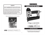
An in-line filter/lubricator/regulator unit can
be installed, as depicted in Figure 2.
This filter/lubricator/regulator unit will
protect your tool from damaging water
build-up, allow you to adjust and maintain
constant air pressure to your tool, and
save you the inconvenience of having to
manually lubricate your tool every time
you use it.
Compressed Air
System
Check the current Grizzly catalog for avail-
ability of this unit. If you plan on install-
ing a filter/lubricator/regulator unit in your
compressed air system, always follow the
connection instructions that come with
the unit.
Exceeding the maximum permissible
operating pressure may damage the
nailers and cause them to malfunc-
tion. To protect yourself from per-
sonal injury, DO NOT allow the air
pressure to exceed the recommended
pressure for these nailers!
Quick
Connector
Quick
Coupler
Air Hose
Quick
Coupler
Quick
Connector
Lubricator
Filter
Regulator
Air
Compressor
Your
Tool
Figure 2. Typical filter/lubricator/regulator installation order.

Model H8232 3-Piece Framing/Finish/Palm Nailer Kit
-8-
A safety mechanism on the nose of the
framing/finish nailer protects against acci-
dental firing. When the trigger is pressed,
the nailer will not fire until the safety nose
mechanism is depressed.
Before you use your nailers for the first
time, perform these safety checks to
ensure the safety nose mechanisms are
operating properly.
Safety Check #1
1. DISCONNECT NAILER FROM THE
AIR SUPPLY!
2. Make sure the magazine is empty and
contains no nails.
3. Make sure the trigger and the safety
nose mechanism move up and down
without sticking.
4. Connect the nailer to the air supply.
5. Without pressing the trigger, depress
the safety nose mechanism against a
scrap piece of wood that is clean and
free of any knots, nails, or other foreign
objects.
— If the nailer does not fire, then the
safety nose mechanism is working
correctly. Proceed to Safety Check
#2.
— If the nailer does fire when you
do this, immediately disconnect the
nailer from the air supply and call
Grizzly Technical Support at (570)
546-9663 for help.
Framing/Finish
Nailer Safety Nose
Mechanism
Note: If you find that the safety nose
mechanism is not moving up and
down properly, check the lubrication
of its sliding components.
Safety Check #2
1. Lift the nailer from the scrap piece of
wood so that the safety nose is not
depressed, point the nailer down and
away from yourself and others, then
pull the trigger.
— If the nailer does not fire when the
trigger is pulled without the safety
nose mechanism being depressed,
then the nailer is working properly.
— If the nailer does fire when you
do this, immediately disconnect the
nailer from the air supply and call
Grizzly Technical Support at (570)
546-9663 for help.
The safety mechanism is a mechanical
device that can fail. Never rely on this
mechanism as an excuse to point the
framing/finish nailer at yourself or any
bystanders. Serious injury may occur.
DO NOT attempt to modify or bypass
the safety nose mechanism to make
the framing/finish nailer fire without
pushing the safety nose down.

Model H8232 3-Piece Framing/Finish/Palm Nailer Kit
-9-
OPERATIONS
Loading
Framing Nailer
Nail Size ......................
1
⁄8" Shank Diameter
Nail Strip Angle .................34º Round Head
Length..............................................2"–3
1
⁄2"
Magazine Capacity ........................ 60 Nails
To load your framing nailer:
1. DISCONNECT NAILER FROM THE
AIR SUPPLY!
2. Grip the nailer firmly and point the nose
down, then pull the magazine pusher
back until the catch lever engages, as
shown in Figure 3.
3. Insert a strip of nails, pointed-end
down, into the magazine as shown in
Figure 4.
Figure 3. Sliding magazine pusher back
and engaging catch lever.
Pusher
4. Tilt the nailer to slide the nails all the
way down to the nose.
5. With one hand on the magazine pusher
for control, release the magazine catch
and slowly allow the pusher to press
against the nails.
Finish Nailer
Nail Size ..................................... 16 Gauge
Nail Length ................................... 1
1
⁄4"–2
1
⁄2"
Magazine Capacity ........................ 74 Nails
To load your finish nailer:
1. DISCONNECT NAILER FROM THE
AIR SUPPLY!
2. Grip the nailer firmly, and pull the
magazine pusher back until the catch
lever engages, as shown in Figure 5.
Figure 4. Loading nails into the magazine.
Figure 5. Sliding magazine pusher back.

Model H8232 3-Piece Framing/Finish/Palm Nailer Kit
-10-
If you have not read the safety instruc-
tions in this manual, do not operate the
nailer.
Before you operate your nailers, place
five to six drops of the included oil into the
quick connect fitting where the nailer con-
nects to the air supply.
Framing & Finish Nailer
1. Connect the air supply to the quick con-
nect fitting.
2. To test for proper nail penetration, hold
the nailer perpendicular to the surface
of a piece of clean scrap wood that is
thick enough for the length of nails you
have loaded.
Operating
5. Pull the trigger.
— If the nail drove into the wood far
enough, continue with your intended
operations.
— If the nail either went too far or not
far enough, then go to the Adjusting
Nail Penetration section on the next
page.
3. Depress the safety nose mechanism
against your workpiece.
4. Before pulling the trigger, make sure
your free hand and other body parts
are positioned out of the way of a
potential path of a nail in case of deflec-
tion.
Note: Deflection is caused when
grain irregularities, knots, or foreign
objects inside the wood cause the
nail to change its path, resulting in
the nail puncturing the surface of the
workpiece, as shown in Figure 7.
Besides damaging your workpiece,
deflection can cause injury if your free
hand is in the path of the deflecting
nail.
Figure 7. Example of nail deflection.
4. Slide the nails all the way down to the
nose of the nailer.
5. Release the magazine pusher by pull-
ing back on the pusher and pushing in
on the catch lever.
Figure 6. Loading nails into magazine
(finish nailer).
3. Insert a strip of nails, pointed-end
down, into the magazine as shown in
Figure 6.

Model H8232 3-Piece Framing/Finish/Palm Nailer Kit
-11-
Depending on the type of stock and nails
you are using, it may be necessary to
adjust the depth of nail penetration for your
framing/finish nailer.
To adjust the nail penetration of your
framing nailer:
1. DISCONNECT NAILER FROM THE
AIR SUPPLY!
2. Use a 4mm hex wrench to loosen the
cap screw shown in Figure 8.
3. Move the nose tip away from the nail-
er body to decrease penetration, and
toward the nailer body to increase
penetration.
Note: The rubber nose tip can be
removed to increase nail penetration
even further.
Adjusting Nail
Penetration
4. Re-tighten the cap screw, then connect
the nailer to the air supply and test the
nail depth.
5. Connect the nailer to the air supply and
test the nail penetration. If necessary,
repeat this entire procedure until the
nail penetration is satisfactory.
Figure 8. Loosening cap screw for depth
adjustment on framing nailer.
Nose Tip
Cap Screw
Palm Nailer
1. Connect the air supply to the quick con-
nect fitting.
2. Hold the nail firmly in place with one
hand as if using a regular hammer.
3. Place the tip of the palm nailer over
the top of the nail. When the ram pin
touches the nail head, the nailer will
automatically begin to hammer the nail
into place.
Note: Set the nail in position with a
short burst of the nailer, then move
your hand away from the nail before
continuing.
4. Hold the nailer in place until the sliding
depth guide is completely depressed
up into the nailer and the nail is fully
hammered into the workpiece.
Note: You can stop the nailer at any
time by simply lifting it away from
the nail. This is useful if you do not
want to countersink the nail into the
workpiece.
If the nailer is allowed to continue
hammering until it stops by itself, it will
countersink the nail to an approximate
depth of 2mm or
5
⁄64".

Model H8232 3-Piece Framing/Finish/Palm Nailer Kit
-12-
3. Locate the opening in the underside of
the nailer safety nose (see Figure 10).
Clearing Jammed
Nails
4. Dislodge the jammed nail with a tool
that will fit in the slot on the underside
of the nose.
5. Throw the damaged nail away and
insert a new nail strip that only contains
clean, undamaged nails. DO NOT use
dirty or damaged nails!
6. Release the catch lever and slowly
let the pusher slide to the front of the
magazine.
Finish Nailer
To clear a jammed nail from the dis-
charge area:
1. DISCONNECT NAILER FROM THE
AIR SUPPLY!
2. Pull back and latch the magazine push-
er, then remove the nail strip from the
magazine.
3. Open the nailer nose by removing the
rubber nose tip, squeezing the nose
release mechanism (see Figure 11),
and opening the nose cover.
Figure 10. Clearing a jammed nail.
Nose Opening
To adjust the nail penetration of your
finish nailer:
1. DISCONNECT NAILER FROM THE
AIR SUPPLY!
2. Rotate the depth adjustment knob (see
Figure 9) clockwise to increase nail
penetration, and counterclockwise to
decrease nail penetration.
Figure 9. Finish nailer depth adjustment
controls.
Safety Nose
Adjustment
Knob
3. Connect the nailer to the air supply and
test the nail penetration. If necessary,
repeat this entire procedure until the
nail penetration is satisfactory.
A jammed nail must be cleared before
using the nailer again.
Framing Nailer
To clear a jammed nail from the dis-
charge area:
1. DISCONNECT NAILER FROM THE
AIR SUPPLY!
2. Pull back and latch the magazine push-
er, then remove the nail strip from the
magazine.

Model H8232 3-Piece Framing/Finish/Palm Nailer Kit
-13-
Figure 11. Nose opened to clear a jam.
Nose Cover
Nose Release
Nose Tip
4. Dislodge the jammed nail with a tool
that will fit in the slot on the underside
of the nose.
5. Throw the damaged nail away and
insert a new nail strip that only contains
clean, undamaged nails. DO NOT use
dirty or damaged nails!
6. Close the nose cover and replace the
nose tip. Then release the catch lever
and let the pusher slide to the front of
the magazine.
Replacing Pistons/
O-Rings
Under heavy use, a piston, piston shaft,
or O-ring may wear out. Replacement is
quick and easy. Contact Grizzly Customer
Service at (800) 523-4777 to obtain the fol-
lowing Piston Repair Kits or the Complete
O-Ring Repair Kits.
Nailer Repair Kit Part Number
Framing Nailer:
Piston Repair Kit ............... PH7665095
O-Ring Repair Kit .............. PH7665096
Finish Nailer:
Piston Repair Kit ............... PH8232091
O-Ring Repair Kit .............. PH8232092
Palm Nailer:
Piston Repair Kit ............... PH6141026
O-Ring Repair Kit .............. PH6141027
Always disconnect air from nailer
whenever servicing! During mainte-
nance, a nailer connected to air may
fire accidentally, causing serious per-
sonal injury!
Framing & Finish Nailer
To replace a piston in your framing or
finish nailer:
1. DISCONNECT NAILER FROM THE
AIR SUPPLY!
2. Remove all nails from the magazine
cartridge, and clean the exterior of the
nailer.
3. Remove the four cap screws on the
back of the nailer, near the exhaust
port.
4. Remove the cap.
5. The top of the piston should now be
visible inside the cylinder, which is
housed in the head of the nailer.
6. Watch the discharge area and push the
top of the piston with your finger. You
will see the piston shaft slide down the
discharge area.

Model H8232 3-Piece Framing/Finish/Palm Nailer Kit
-14-
4. Push the ram pin towards the inside of
the nailer—this will push the cylinder
free of the housing.
5. Grab the ram pin and pull the piston
from the cylinder.
6. Apply a thin film of pneumatic tool oil on
the new O-ring and place it on the new
piston.
7. Insert the new piston into the cylinder.
The new piston should easily slide into
the cylinder. DO NOT force the piston
into the cylinder! If the piston is not
easily inserted, check the alignment of
the piston inside the cylinder.
8. After the piston is inserted correctly,
place the cylinder back in the nailer
housing. If seated correctly, the cylin-
der will snap into place.
9. Push the cylinder collar down into the
housing as far as it will go. The horizon-
tal air slots on the cylinder sides should
be visible.
10. Replace the rear cap and secure it
with the four cap screws removed in
Step 3.
11. Re-install the flat washer, compression
spring, depth guide, and nose piece
onto the front of the nailer, then use
a 19mm wrench to tighten the nose
piece.
Note: For more assistance, or to install
a complete O-ring set, refer to the
appropriate breakdown diagram in the
back of this manual for component
locations.
7. Taking care not to scratch or dent the
nailer parts, use a wooden dowel or
similarly shaped tool to push the piston
shaft back inside the nailer until you
can grip the piston head and remove
it from the cylinder. Clean and inspect
the parts for cracks, wear, or burrs.
8. Apply a thin film of pneumatic tool oil on
the new O-ring and place it on the new
piston.
9. Insert the new piston in the cylinder.
Make sure that the grooves on the pis-
ton shaft line up with those on the guide
at the bottom of the cylinder. The new
piston should easily slide into the cyl-
inder. DO NOT force the piston into
the cylinder! If the piston is not easily
inserted, double-check the alignment of
the piston shaft with the grooves on the
guide.
10. After the piston is inserted correctly,
close the magazine. Replace the rear
cap assembly and secure it with the
four cap screws removed in Step 3.
Note: For more assistance, or to install
a complete O-ring set, refer to the
appropriate breakdown diagram in the
back of this manual for component
locations.
Palm Nailer
To replace a piston for your palm nail-
er:
1. DISCONNECT NAILER FROM THE
AIR SUPPLY!
2. Using a 19mm wrench, remove the
nose piece, depth guide, compression
spring, and flat washer.
3. Use the 4mm hex wrench to remove
the four cap screws on the nailer cap,

Model H8232 3-Piece Framing/Finish/Palm Nailer Kit
-15-
CLEANING & LUBRICATION
Cleaning
Use non-flammable solvent to clean the
nose assembly of the nailer. Always be
sure that the nailer is dry before using it
again.
Do not allow dust, chips, sand, etc. into
the air connectors or into the body of the
nailer; this may result in leaks and damage
to the nailer and the air couplings.
Lubricating
Standard pneumatic tool oil has been
included with your new Grizzly nailer to
help maintain its useful life. Place two to
six drops of oil in the nailer air inlet (as
shown in Figure 12) before every use, or
after 2 hours of continuous use.
Wipe off any excess oil near the nailer
exhaust to avoid dust build-up. When the
oil that was included with the nailer has
been completely used, replace it with
Grizzly Model G2820 Pneumatic Tool Oil.
Another option to manual oiling would be
to install a lubricator in your air compres-
sor line. If your air compressor line already
has a lubricator, then regular lubrication
of your nailer will not be necessary. Just
make sure there is always oil in the lubri-
cator.
Figure 12. Lubricating nailer via air inlet.
Never clean this tool with gasoline
or other flammable liquids. Vapors
in the tool may ignite, causing the
tool to explode. Ignoring this warning
may lead to serious personal injury or
even death!

Model H8232 3-Piece Framing/Finish/Palm Nailer Kit
-16-
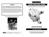
H8232 PARTS
Framing Nailer Parts Breakdown

Model H8232 3-Piece Framing/Finish/Palm Nailer Kit
-17-
Framing Nailer Parts List
REF PART # DESCRIPTION REF PART # DESCRIPTION
1 PSB31M CAP SCREW M8-1.25 X 25 52 PH8233052 COPPER COLLAR
2 PH8233002 EXHAUST PORT 53 PH8233053 SAFETY NOSE CASE
3 PH8233003 SPACER 54 PORS060 O-RING 59.5 X 2.0 S60
4 PH8233004 CIRCULAR SPRING 55 PH8233055 DRIVE GUIDE
5 PH8233005 RETAINING RING 56 PLW04M LOCK WASHER 8MM
6 PSB06M CAP SCREW M6-1 X 25 57 PSB13M CAP SCREW M8-1.25 X 30
7 PLW03M LOCK WASHER 6MM 58 PSB26M CAP SCREW M6-1 X 12
8 PH8233008 CYLINDER PLUG 59 PH8233059 MAGAZINE
9 PSS07M SET SCREW M5-.8 X 5 60 PW03M FLAT WASHER 6MM
10 PH8233010 CYLINDER COVER 61 PLN03M LOCK NUT M6-1
11 PH8233011 PISTON STOP 62 PH8233062 PUSHER
12 PH8233012 SPRING SEAT 63 PSB18M CAP SCREW M4-.7 X 8
13 PH8233013 COMPRESSION SPRING 64 PLN01M LOCK NUT M4-.7
14 PH8233014 SPECIAL WASHER 65 PSB46M CAP SCREW M4-.7 X 40
15 PH8233015 PISTON COLLAR 66 PH8233066 SAFETY SHAFT
16 POR0079 O-RING 42.3 X 5 67 PH8233067 SAFETY SHAFT CASING
17 PH8233017 PISTON 68 PH8233068 PIN CASING
18 PORG055 O-RING 54.4 X 3.1 G55 69 PH8233069 SPECIAL PIN
19 POR0080 O-RING 88 X 3 70 PH8233070 PUSHER CATCH
20 PH8233020 THREADED RETAINING RING 71 PRP42M ROLL PIN 3 X 20
21 PH8233021 SEALING RING 72 PRP03M ROLL PIN 5 X 20
22 PH8233022 CYLINDER 73 PSB93M CAP SCREW M3-.5 X 14
23 PH8233023 BUMPER 74 PH8232074 LOCK NUT M3-.5
24 PH8233024 GASKET 75 PH8233075 PIN B4 X 30
25 PH8233025 NAILER BODY 76 PH8233076 TORSION SPRING
26 PH8233026 SPACER 77 PH8233077 SPRING CORE
27 PH8233027 PISTON VALVE SEAT 78 PH8233078 PIN B5 X 12
28 PORP015 O-RING 14.8 X 2.4 P15 79 PH8233079 RELEASE LATCH
29 PORS018 O-RING 17.5 X 1.5 S18 80 PH8233080 LATCH SPRING
30 PH8233030 PISTON VALVE 81 PSB38M CAP SCREW M5-.8 X 25
31 PORP006 O-RING 5.8 X 1.9 P6 82 PW02M FLAT WASHER 5MM
32 PORP007 O-RING 6.8 X 1.9 P7 83 PH8233083 LATCH BRACKET
33 PORP009 O-RING 8.8 X 1.9 P9 84 PLN02M LOCK NUT M5-.8
34 PH8233034 COMPRESSION SPRING 85 PH8233085 RUBBER GRIP
35 PH8233035 TRIGGER SHAFT 86 PH8233086 GASKET
36 PORS003 O-RING 2.5 X 1.5 S3 87 PH8233087 END CAP
37 PORP020 O-RING 19.8 X 2.4 P20 88 PSB15M CAP SCREW M5-.8 X 20
38 PH8233038 TRIGGER SEAT 89 PLW01M LOCK WASHER 5MM
39 PH8233039 TRIGGER PIN 90 PH8233090 AIR FITTING 1/4 NPT
40 PH8233040 TRIGGER 91 PH8233091 AIR FITTING DUST CAP
41 PH8233041 RUBBER RETAINING RING 92 PH8233092 PISTON REPAIR KIT
42 PH8233042 SAFETY CATCH 93 PH8233093 O-RING REPAIR KIT
43 PRP02M ROLL PIN 3 X 16 94 PH8233094 CARRYING CASE
44 PH8233044 SLIDING BRACKET 95 PH8233095 SAFETY GOGGLES
45 PRP16M ROLL PIN 3 X 25 96 PAW03M HEX WRENCH 3MM
46 PH8233046 COMPRESSION SPRING 97 PAW04M HEX WRENCH 4MM
47 PSB03M CAP SCREW M5-.8 X 8 98 PAW05M HEX WRENCH 5MM
48 PW02M FLAT WASHER 5MM 99 PAW06M HEX WRENCH 6MM
49 PH8233049 ADJUSTING NUT 99-1 PH8232099-1 WARNINGS LABEL
50 PH8233050 SAFETY YOKE 99-2 PH8232099-2 GRIZZLY LOGO LABEL
51 PH8233051 SAFETY NOSE 99-3 PH8232099-3 TOOL ID LABEL

Model H8232 3-Piece Framing/Finish/Palm Nailer Kit
-18-
Finish Nailer Parts Breakdown
/