Page is loading ...

Backyard Mosquito Repellent System
Model
HVK400
Section Page
Kit Contents .......................................................... 2
Tools Needed ........................................................ 2
Important Safety Instructions .............................. 3
Locate Controller ................................................. 4
Mount Controller .................................................. 4
Locate The Fixtures ............................................ 5
Fixture Installation ................................................ 5
Connect Wiring for Repellent Fixtures ................. 6
Test System Prior to Cable Burial ........................ 7
Bury Cable and Connectors ................................. 7
Accessories ......................................................... 7
Controller Operation ............................................ 8
FCC Information .................................................. 9
Address & Warranty ............................................. 9
Service Numbers ................................................. 9

2
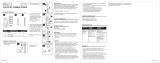
Kit Contents
Tools Needed
CONTROLLER
WITH 65-FT.
WIRE (1)
CONTROLLER
MOUNTING
PLATE (1)
STRIKER
CAP (1)
NUTONE HAVEN
REPELLENT
CARTRIDGES (4)
FIXTURE HEAD ASSEMBLY (4)
FIXTURE STEM (4)
FIXTURE STAKE (4)
WIRE CONNECTORS (4)
SELF-TAPPING SCREWS
M4 x 10mm (2)
HAMMER
PHILLIPS
SCREWDRIVER
LEVEL
REQUIRED
SHOVEL
OR
SOD
CUTTER
OPTIONAL
PLIERS
POWER DRIVER
WOOD SCREWS
M4 x 14mm (4)

3
IMPORTANT SAFETY INSTRUCTIONS
SAVE THESE INSTRUCTIONS — This manual contains important safety and
operating instructions for power units.
FOR OUTDOOR USE ONLY.
When using electrical products, basic precautions should always be practiced
including the following:
1. READ AND FOLLOW ALL SAFETY INSTRUCTIONS.
2. Read and follow all instructions that are on the product or provided with
the product.
3. Do not use an extension cord.
4. Do not install or use within 10 feet of a pool or any other body of water.
5. Do not use in a bathroom.
6. WARNING: RISK OF ELECTRIC SHOCK. When used outdoors, install
only to a Weatherproof Receptacle protected by a Class A GFCI. If one
is not provided, contact a qualified electrician for proper installation.
Refer to the Canadian Electrical Code and relevant Building Codes for
the installation of this product including these requirements for fire-rated
construction. All installation work and electrical wiring must be performed
by qualified personnel.
7. WARNING: RISK OF ELECTRIC SHOCK. Mount the controller at a
height greater than 12 inches from the ground surface.
8. CAUTION: OUTDOOR USE ONLY: Toxic materials are dispensed, do not
use near a kitchen where there is uncovered food or occupied sleeping
areas.

4
Locate Controller
1. Locate closest exterior electrical outlet near
desired installation area. (Fig. 1)
2. Controller must be installed a minimum of
12 inches above ground level and within 18
inches of an electrical outlet. (Fig. 1)
3. Consult a local electrician if an exterior
electrical outlet needs to be installed.
NOTE: Controller requires an input voltage
of 120 VAC, 60Hz.
Mount Controller
1. Remove metal plate from back of
controller and hold against wall.
2. Ensure the plate is level before
screwing to wall. Plate must be
installed a minimum of 12 inches
above ground level.
3. Screw plate to wall through four
holes using M4 x 14mm wood screws
provided. (Fig. 2)
4. Once mounting plate is secure, align
tabs on mounting plate with two
recessed slots on back of controller
and drop into place.
5. Attach controller to bottom lip of mounting
plate using M4 x 10mm self tapping screws
provided.
(Fig. 3)
NOTE: Mounting surfaces can vary, if installing
on brick use fasteners suitable for application.
GROUND
MIN.
12 inches
GROUND
MIN.
12 inches
MAX.
18 inches
Fig. 1
Fig. 2
Fig. 3

5
Locate the Fixtures
1. Route the 65 feet of low voltage
wire (connected to controller)
around perimeter of desired
protection area. (Fig. 4)
2. Fixtures should be placed 12
feet or less apart surrounding
perimeter of protection area.
(Fig. 5)
3. Mark location for each fixture.
NOTE: Do not connect additional wire as this
may cause system to not function properly.
NOTE: Controller can only power up to four
fixtures.
Fixture Installation
1. Install ground stakes. Loosen hard soil and remove stones and rocks
before attempting to install ground stakes. Use provided striker cap to
protect stakes when hammering. After installation,
stake flange should be flush with grade level.
(Fig. 6)
2. Remove top of fixture by squeezing two
buttons and set aside for use later. (Fig. 7)
STRIKER
CAP
Fig. 4
Fig. 5
Fig. 6
Fig. 7

6
3. Guide fixture wire through metal
stem. Insert stem into fixture head
by aligning pin in stem with groove
in fixture head and press firmly
until you hear a click. (Fig. 8)
4. Pull fixture wiring completely
through notch in ground stake.
Push metal fixture stem into
ground stake by aligning pin in
stem with groove in ground stake.
Press firmly until you hear a click.
(Fig. 9)
5. Refer to separate instruction sheet
for repellent bottle attachment inside fixture.
6. Replace fixture head assemblies on all fixtures removed in Fig. 7.
Connect Wiring for Repellent Fixtures
1. Open main section of clip on the connector.
(Fig. 10)
2. Insert controller wire into main section of
connector. Each side of the wire needs to align
with the piercing contacts inside the main
section.
3. Squeeze two sides of connector until it clicks.
4. Locate end of fixture wires.
(Fig. 11)
5. Pull the two wires apart
approximately 3 inches.
6. Open two wire compartments
on connector.
7. Insert each fixture wire end
into opening until it stops
(approximately 1/2”) and press
closed until it clicks.
WIRE
COMPARTMENTS
FIXTURE
WIRES
Fig. 8
PIN
GROOVE
STAKE
NOTCH
Fig. 9
PIN
GROOVE
PIN
Fig. 10
Fig. 11
PIERCING
CONTACTS

7
Test System Prior to Cable Burial
1. Before the cable is buried, power system on and ensure green LED
indicator light on top of each fixture is illuminated.
NOTE: Controller always needs to be turn ON manually by pressing
the ON/OFF button. Not compatible with external timer.
2. If lights do not illuminate try the following troubleshooting tips:
• Make sure controller is plugged into a working 120 volt wall outlet.
• If wall outlet is operated by a switch, make sure it is turned on.
• Make sure branch circuit breaker is not tripped.
• Make sure wire connector is piercing both wires correctly.
• Make sure fixture wire leads are tight in connector.
• Make sure wire did not get cut during burying process.
• Make sure top of fixture is seated properly on the base.
Bury Cable and Connectors
1. Once system is operating properly, bury and
backfill all wire and connectors for the system
(shovel, or sod cutter recommended). (Fig. 12)
National Electrical Code states burial depth of the
wiring should not be more than 6” below grade.
Check local codes to ensure compliance.
Fig. 12
Accessories
HVR400 - Repellent Refills
Four pack of replacement repellent cartridges.

8
Function Operation LED Indication Troubleshooting
Power Button
(left)
Reset Button
(Right)
System On/
Off.
Press. Displays solid
green.
Reset 4
Hour System
Timer
(Before
Timer
Expires).
Single quick
press.
LED will fl ash
green quickly 2
times to indicate
timer is now
reset to 4 hours.
Low
Repellent.
LED will
continually
fade on and off
slowly.
Reset
195 Hour
Repellent
Timer.
Press and
hold for 5
seconds (can
be reset at
any time).
LED will Flash 5
times then turn
solid green.
Low Voltage
Indication.
LED will fl ash
once every
4 seconds.
This warning
indicates voltage
of system is low
and system may
not be functioning
fully.
Short Circuit
Protection.
LED will
continually fl ash
rapidly.
This fault mode
protects product
from damage.
Potential
issues include
improper fi xture
connection, or
shorted wire
connections.
The system
installation needs
to be inspected.
To reset, unplug
for 30 seconds
and reconnect
controller power
cord from outlet.
Controller Operation

9
Address & Warranty
Broan-NuTone LLC 926 W. State Street, Hartford, WI 53027
See www.nutone.com for warranty information
Service Numbers
IN U.S.A. CALL:
Customer Service 1-888-336-3948
FCC Information
FCC & IC Compliance
This device complies with FCC Part 15, Subpart B and the Canadian ICES-003.
Operation is subject to the following two conditions: (1) this device may not
cause harmful interference, and (2) this device must accept any interference
received including interference that may cause undesired operation. This
class B digital apparatus meets all requirements of the Canadian Interference
Causing Equipment Regulations CAN ICES-3 (B) / NMB-3 (B).
CAUTION: Changes or modifications not expressly approved by NuTone
could void your authority to use this equipment.
These limits are designed to provide reasonable protection against harmful
interference in a residential installation. This equipment generates uses
and can radiate radio frequency energy and, if not installed and used in
accordance with the instructions, may cause harmful interference to radio
communications. However, there is no guarantee that interference will not
occur in a particular installation. If this equipment does cause harmful
interference to radio or television reception, which can be determined by
turning the equipment off and on, the user is encouraged to try to correct the
interference by one or more of the following measures:
• Reorient or relocate the receiving antenna.
• Increase the separation between the equipment and receiver.
• Connect the equipment into an outlet on a circuit different from that to
which the receiver is connected.
• Consult the dealer or an experienced radio/TV technician for help.

10

11
Sistema repelente de mosquitos para patio
Modelo
HVK400
Sección Página
Contenido del juego .................................................12
Herramientas necesarias .........................................12
Instrucciones importantes de seguridad ..................13
Localice el controlador .............................................14
Monte el controlador ................................................14
Localice los accesorios ...........................................15
Instalación del accesorio ........................................ 15
Conecte el cableado para los accesorios
delrepelente ............................................................ 16
Pruebe el sistema antes de poner el cable
bajo tierra .................................................................17
Ponga el cable y los conectores bajo tierra ............17
Accesorios ..............................................................17
Operación del controlador .......................................18
Información de la FCC ............................................19
Dirección y garantía ................................................19
Números de servicio ...............................................19

12
Contenido del juego
Herramientas necesarias
CONTROLADOR
CON CABLE
DE 65 PIES (20 M)
(1)
PLACA DE
MONTAJE DEL
CONTROLADOR (1)
TAPA DE
GOLPEO (1)
CARTUCHOS
DE REPELENTE
NUTONE HAVEN (4)
CONJUNTO DEL CABEZAL DEL
ACCESORIO (4)
VÁSTAGO DEL ACCESORIO (4)
ESTACA DEL ACCESORIO (4)
CONECTORES DE CABLE (4)
TORNILLOS
AUTORROSCANTES
M4 X 10 MM (2)
MARTILLO
DESTORNILLADOR
PHILLIPS
NIVEL
REQUERIDAS
PALA O
CORTADOR
DE CÉSPED
OPCIONAL
ALICATES
TALADRO
ELÉCTRICO
TORNILLOS PARA MADERA
M4 X 14 MM (4)

13
INSTRUCCIONES IMPORTANTES DE
SEGURIDAD
GUARDE ESTAS INSTRUCCIONES — Este manual contiene instrucciones
importantes de seguridad y operación para las unidades eléctricas.
SOLO PARA USO EXTERIOR.
Cuando use productos eléctricos, siempre debe seguir precauciones
básicas, entre las que se incluyen:
1. LEA Y CUMPLA TODAS LAS INSTRUCCIONES DE SEGURIDAD.
2. Lea y cumpla todas las instrucciones que están en el producto o que se
incluyen con el producto.
3. No utilice una extensión eléctrica.
4. No instale ni use a menos de 10 pies (3 m) de una piscina o de otro
cuerpo de agua.
5. No lo use en un baño.
6. ADVERTENCIA: RIESGO DE DESCARGA ELÉCTRICA. Al usar en
exteriores, instale únicamente en un receptáculo a prueba de intemperie
protegido por un GFCI Clase A. Si no se incluye uno, comuníquese
con un electricista calificado para instalarlo adecuadamente. Consulte
el Código Eléctrico Canadiense y los códigos de construcción
pertinentes para instalar este producto, incluidos estos requisitos para
construcciones resistentes al fuego. Todo trabajo de instalación y
cableado eléctrico debe realizarlo personal calificado.
7. ADVERTENCIA: RIESGO DE DESCARGA ELÉCTRICA. Monte el
controlador a una altura superior a 12 pulgadas (30 cm) de la superficie
del suelo.
8. PRECAUCIÓN: SÓLO PARA USO EXTERIOR: Se dispensan
materiales tóxicos, no los utilice cerca de una cocina donde haya comida
descubierta o áreas de dormir ocupadas.

14
Localice el controlador
1. Localice el tomacorriente eléctrico exterior
más cerca de la zona de instalación
deseada. (Fig. 1)
2. El controlador debe instalarse a un mínimo
de 12 pulgadas (30 cm) por arriba del nivel
del suelo y a menos de 18 pulgadas (45cm)
de un tomacorriente eléctrico. (Fig. 1)
3. Consulte con un electricista local si es
necesario instalar un tomacorriente
eléctrico exterior.
NOTA: El controlador requiere un voltaje
de entrada de 120 VCA y 60 Hz.
Monte el controlador
1. Retire la placa metálica de la parte
posterior del controlador y sosténgala
contra la pared.
2. Asegúrese de que la placa esté
nivelada antes de atornillarla a la
pared. La placa debe instalarse a un
mínimo de 12 pulgadas (30 cm) por
arriba del nivel del suelo.
3. Atornille la placa a la pared a través
de cuatro orificios, usando los
tornillos para madera M4 x 14 mm
suministrados. (Fig. 2)
4. Una vez que esté bien firme la placa
de montaje, alinee las lengüetas en
la placa de montaje con dos ranuras
ahuecadas en la parte posterior del
controlador y deje caer en su lugar.
5. Fije el controlador al reborde inferior de
la placa de montaje usando los tornillos
autorroscantes M4 x 10 mm suministrados.
(Fig. 3)
NOTA: Las superficies de montaje pueden variar.
Si instala en ladrillo use sujetadores adecuados
para la aplicación.
TIERRA
MÍN.
12 pulg. (30 cm)
TIERRA
MÍN.
12 pulg.
(30 cm)
MÁX
18 pulg.
(45 cm)
Fig. 1
Fig. 2
Fig. 3

15
Localice los accesorios
1. Pase los 65 pies (20 m)
de cable de bajo voltaje
(conectado al controlador)
alrededor del perímetro del
área de protección deseada.
(Fig. 4)
2. Los accesorios se deben
colocar con una separación
de 12 pies (3.6 m) o menos
rodeando el perímetro de la
zona de protección. (Fig. 5)
3. Marque la ubicación para cada accesorio.
NOTA: No conecte cable adicional, pues
podría ocasionar que el sistema no funcione
adecuadamente.
NOTA: El controlador solo puede energizar hasta
cuatro accesorios.
Instalación del accesorio
1. Instale las estacas para el suelo. Afloje el suelo
duro y retire piedras y rocas antes de tratar
de instalar estacas en el suelo. Use la tapa
de golpeo incluida para proteger las estacas
cuando les pegue con el martillo. Después de
la instalación, la brida de la estaca debe estar
anivel con el rasante. (Fig. 6)
2. Quite la parte superior del accesorio
apretando dos botones y dejando a un
ladopara un uso posterior. (Fig. 7)
TAPA DE
GOLPEO
Fig. 4
Fig. 5
Fig. 6
Fig. 7

16
3. Guíe el alambre del accesorio
por el vástago de metal. Inserte
el vástago en el cabezal del
accesorio alineando la clavija en el
vástago con la ranura en el cabezal
y presionando con firmeza hasta
que escuche un clic. (Fig. 8)
4. Hale totalmente el alambre del
accesorio por la muesca en la
estaca para el suelo. Empuje el
vástago del accesorio de metal en
la estaca para el suelo alineando la
clavija en el vástago con la ranura
en la estaca. Presione con firmeza
hasta que escuche un clic. (Fig. 9)
5. Consulte la hoja de instrucciones por separado para fijar la botella de
repelente dentro del accesorio.
6. Vuelva a colocar los conjuntos de cabezales en todos los accesorios que
quitó en la Figura 7.
Conecte el cableado para los accesorios
delrepelente
1. Abra la sección principal del sujetador en el
conector. (Fig. 10)
2. Inserte el cable del controlador en la sección
principal del conector. Es necesario que cada
lado del alambre se alinee con los contactos
de perforación dentro de la sección principal.
3. Apriete dos lados del conector hasta que
haga clic.
4. Localice el extremo de los
cables del accesorio. (Fig. 11)
5. Separe los dos cables
aproximadamente 3 pulg.
(7.5cm).
6. Abra los dos compartimientos
de cables en el conector.
7. Inserte cada extremo del cable
del accesorio en la apertura
hasta que se detenga aprox.
a 1/2 pulg. (1.3 cm) y presione
para cerrar hasta que hagaclic.
COMPARTIMIENTOS
DE CABLES
CABLES DEL
ACCESORIO
Fig. 8
RANURA
DE LA
CLAVIJA
MUESCA
DE LA
ESTACA
Fig. 9
RANURA
DE LA
CLAVIJA
CLAVIJA
Fig. 11
Fig. 10
CONTACTOS DE
PERFORACIÓN

17
Pruebe el sistema antes de poner el cable
bajo tierra
1. Antes de poner el cable bajo tierra, encienda el sistema y asegúrese de que
la luz indicadora de LED color verde se encienda en la parte superior de
cada accesorio.
NOTA: Siempre es necesario que el controlador se ENCIENDA manualmente
presionando el botón ON/OFF. No es compatible con un temporizador externo.
2. Si las luces no se encienden, pruebe los siguientes consejos para solucionar
problemas:
• Asegúrese de que el controlador esté conectado en un tomacorriente de
pared de 120 voltios que funcione.
• Si el tomacorriente es operado por un interruptor, asegúrese de que
estéencendido.
• Asegúrese de que el disyuntor del ramal no esté activado.
• Asegúrese de que el conector de alambres perfore correctamente los
dosalambres.
• Asegúrese de que los cables del accesorio estén apretados en el conector.
• Asegúrese de que el alambre no se corte al ponerlo bajo tierra.
• Asegúrese de que la parte superior del accesorio esté bien asentada
enlabase.
Ponga el cable y los conectores bajo tierra
1. Una vez que el sistema funcione adecuadamente,
ponga bajo tierra y rellene todos los alambres y
conectores del sistema (se recomienda una pala o un
cortador de césped). (Fig. 12)
El Código Eléctrico Nacional declara que la profundidad
para poner bajo tierra el cable no debe ser mayor de
6pulg. (15 cm) por debajo del rasante. Verifique los
códigos locales para garantizar el cumplimiento.
Fig. 12
Accesorios
HVR400 - Repuestos de repelente
Paquete con cuatro cartuchos de repelente de reemplazo.

18
Función Funcionamiento Indicación de
LED
Resolución de
problemas
Botón de
encendido
(izquierdo)
Botón de
reinicio
(derecho)
Encendido/
apagado del
sistema.
Presione. Enciende en
color verde
continuo.
Reinicio de
4 horas del
temporizador del
sistema (antes
de que venza el
temporizador).
Presione
rápido una vez.
El LED destellará
2 veces
rápidamente en
color verde para
indicar que el
temporizador se
ha reiniciado a
4horas.
Repelente en
nivel bajo.
El LED se
desvanecerá
enciendo y
apagando lenta y
continuamente.
Reinicio del
temporizador
del repelente de
195horas.
Presione y
sostenga
presionado
5segundos (se
puede reiniciar
en cualquier
momento).
El LED destellará
5 veces y luego
quedará en color
verde continuo.
Indicación de
bajo voltaje.
El LED destellará
una vez cada
4segundos.
Esta advertencia indica
que el voltaje del
sistema está bajo y
que tal vez no funcione
plenamente.
Protección
contra cortos
circuitos.
El LED seguirá
destellando
rápidamente.
Este modo de falla
protege al producto
contra daños. Los
posibles problemas
incluyen una
conexión inadecuada
del accesorio o
conexiones de alambre
en corto circuito. Es
necesario inspeccionar
la instalación del
sistema. Para
reiniciar, desconecte
30segundos
y reconecte el
cable eléctrico del
controlador en el
tomacorriente.
Operación del controlador

19
Dirección y garantía
Broan-NuTone LLC 926 W. State Street, Hartford, WI 53027
Consulte la información de la garantía en www.nutone.com
Números de servicio
EN EE.UU. LLAME A:
Servicio a clientes: 1-888-336-3948
Información de la FCC
Cumplimiento con la FCC y el IC
Este dispositivo cumple con la parte 15, Subparte B de la FCC y con la ICES-003
de Canadá. La operación está sujeta a las dos condiciones siguientes: (1) Este
dispositivo no puede ocasionar interferencias nocivas, y (2) Este dispositivo
debe aceptar cualquier interferencia recibida, incluida la interferencia que
pueda provocar un funcionamiento no deseado. Este aparato digital clase B
cumple con todos los requisitos de los reglamentos canadienses de equipos
que ocasionan interferencias CAN ICES-3 (B) / NMB-3 (B).
PRECAUCIÓN: Los cambios o modificaciones no aprobados
expresamente por NuTone pueden anular su autoridad para usar este
equipo.
Estos límites están diseñados para brindar una protección razonable contra
las interferencias nocivas en una instalación residencial. Este equipo genera
usos y puede radiar energía de radiofrecuencia que, si no se instala y
utiliza de acuerdo con las instrucciones, podría causar interferencia nociva
a las comunicaciones por radio. No obstante, no hay garantía de que no se
generará interferencia en una instalación particular. Si el equipo provoca
interferencias nocivas en la recepción de señales de radio o de televisión, lo
cual se puede determinar apagando y encendiendo el equipo, se recomienda
al usuario que trate de corregir la interferencia mediante una o más de las
siguientes medidas:
• Reorientar o reubicar la antena de recepción.
• Aumentar la separación entre el equipo y el receptor.
• Conectar el equipo en un tomacorriente en un circuito diferente a aquel
donde esté conectado el receptor.
• Pida ayuda al distribuidor o a un técnico experimentado en radio y TV.

20
99046080B
/