Page is loading ...

Startup
Servo Drive AX5000
(1.5 A – 40 A)
Please read this document carefully before installing and commissioning the servo drive.
Version : 4.5
Date: 2015
-04-01
Language: English
Article no.: TDmlAX
-5000-0000-0200
BECKHOFF

1 Foreword BECKHOFF Drive Technology
2 Version : 4.5 AX5000
Notes:

BECKHOFF Drive Technology 1 Foreword
AX5000 Version : 4.5 3
Chapter Page
Table of Contents - AX5000 Startup
1 Foreword ............................................................................................................... 5
1.1 Notes on the documentation ............................................................................... 5
1.2 Disclaimer ........................................................................................................... 5
1.3 Trademarks ........................................................................................................ 5
1.4 Patent Pending ................................................................................................... 5
1.5 Copyright ............................................................................................................ 6
1.6 Documentation issue status ............................................................................... 6
1.7 Appropriate use .................................................................................................. 7
1.7.1 Dual Use (EU 1384/2014) .................................................................................. 7
1.8 Documented servo drives ................................................................................... 8
2 Safety .................................................................................................................... 9
2.1 General safety instructions ................................................................................. 9
2.1.1 Safety rules ........................................................................................................ 9
2.1.2 Disclaimer ........................................................................................................... 9
2.1.3 Description of safety symbols ............................................................................. 9
2.1.4 Personnel qualification ..................................................................................... 10
2.2 Special safety instructions for AX5000 ............................................................. 10
3 Guidelines and Standards ................................................................................. 12
3.1 CE conformity ................................................................................................... 12
3.2 Electromagnetic compatibility ........................................................................... 12
3.3 UL-Listing in USA and Canada ......................................................................... 13
3.3.1 UL-specific chapter changes ............................................................................ 13
3.3.2 UL-specific chapter ........................................................................................... 13
3.3.3 UL-specific notes .............................................................................................. 14
3.4 Electrical isolation according to EN 50178 / VDE 160 ...................................... 14
4 Product description ........................................................................................... 15
4.1 Type code ......................................................................................................... 15
4.2 Scope of supply ................................................................................................ 15
4.2.1 Standard scope of supply ................................................................................. 15
4.2.2 Accessories ...................................................................................................... 16
4.3 Name plate ....................................................................................................... 16
4.4 Technical data .................................................................................................. 17
4.4.1 Permissible ambient and operating conditions ................................................. 17
4.4.2 Electrical data - single-channel servo drive (AX51xx)....................................... 17
4.4.2.1 Single-phase connection .................................................................................. 17
4.4.2.2 Three-phase connection ................................................................................... 18
4.4.3 Electrical data - two-channel servo drive (AX52xx) .......................................... 19
4.4.3.1 Single-phase connection .................................................................................. 19
4.4.3.2 Three-phase connection ................................................................................... 19
4.4.4 Mechanical data (single-channel servo drive) .................................................. 20
4.4.5 Mechanical data (two-channel servo drive) ...................................................... 20
4.5 General overview (AX5101 – AX5112 and AX520x) ........................................ 21
4.6 General overview (AX5118, AX5125 und AX5140) .......................................... 22
4.7 Overview of connectors/terminal points ............................................................ 23

1 Foreword BECKHOFF Drive Technology
4 Version : 4.5 AX5000
4.7.1 X01 - wide voltage input ................................................................................... 23
4.7.2 X02 - DC link (AX5101 - AX5125 und AX520x) ................................................ 23
4.7.3 X02 - DC link (Only AX5140) ............................................................................ 23
4.7.4 X03 - 24 V
DC
supply ......................................................................................... 23
4.7.5 X04, X05 - EtherCAT connection ..................................................................... 24
4.7.6 X06 – Digital I/Os ............................................................................................. 24
4.7.7 X11 (channel A) , X21 (channel B) - feedback, high-resolution ........................ 25
4.7.8 X12 (channel A) , X22 (channel B) - resolver/hall ............................................ 25
4.7.9 X13 (channel A) , X23 (channel B) - motor connection (power) ....................... 26
4.7.10 X13 - motor connection (power - only AX5140) ................................................ 26
4.7.11 X14 (channel A), X24 (channel B)-motor brake, thermal contact, OCT ............ 26
4.7.12 X07 – internal and external brake resistor ........................................................ 27
4.8 Dimensions ...................................................................................................... 28
5 Installation .......................................................................................................... 30
5.1 Mechanical installation ..................................................................................... 30
5.1.1 Installation in the control cabinet ...................................................................... 30
5.1.1.1 Installation example - AX5101-AX5112 and AX5201-AX5206 ......................... 31
5.1.1.2 Installation example - AX5118, AX5125 and AX5140 ...................................... 31
5.2 Electrical installation ......................................................................................... 32
5.2.1 Mains supply connection (X01) ........................................................................ 33
5.2.1.1 External protection for individual devices, CE-compliant .................................. 33
5.2.1.2 Internal protection, CE-compliant ..................................................................... 33
5.2.1.3 External protection, UL-compliant .................................................................... 34
5.2.1.4 Internal protection, UL-compliant ..................................................................... 34
5.2.1.5 External drive system protection ...................................................................... 35
5.2.2 24 V
DC
- supply network connection (X03) ....................................................... 36
5.2.3 Connection of several servo drives to form a drive system .............................. 36
5.2.3.1 Connection example - module AX5901 and AX5911 (AX Bridge) .................... 37
5.2.3.2 Connection example - wiring in series without AX Bridge ................................ 38
5.2.4 Configuration example, general ....................................................................... 39
5.2.5 Connection diagram AX5101 – AX5112 and AX520x ...................................... 40
5.2.6 Connection diagram AX5118, AX5125 and AX5140 ........................................ 41
5.3 Motors and cables ............................................................................................ 42
6 Important information for commissioning ....................................................... 43
7 Project planning – important information ........................................................ 44
7.1 Drive train design ............................................................................................. 44
7.1.1 Control quality, mass inertia ratio and load connection .................................... 44
7.2 Energy management ........................................................................................ 44
7.3 EMC, earthing, screen connection and potential .............................................. 45
7.4 Control cabinet ................................................................................................. 45
8 Appendix ............................................................................................................ 46
8.1 Support and Service ......................................................................................... 46
8.1.1 Beckhoff's branch offices and representatives ................................................. 46
8.1.2 Beckhoff Headquarters..................................................................................... 46
8.1.3 Beckhoff Support .............................................................................................. 46
8.1.4 Beckhoff Service .............................................................................................. 46

BECKHOFF Drive Technology 1 Foreword
AX5000 Version : 4.5 5
1 Foreword
1.1 Notes on the documentation
This description is only intended for trained specialists in control, automation and drive
engineering who are familiar with the applicable national standards. It is essential that the
following notes and explanations are followed when installing and commissioning these
components. The responsible staff must ensure that the application or use of the products
described satisfy all the requirements for safety, including all the relevant laws, regulations,
guidelines and standards. The "General safety instructions" and "Special safety instructions
for AX5000" sections are also essential.
CAUTION
Hazard to individuals!
Further and more detailed information regarding the individual sections and
safety can be found in the “AX5000 User manual” on the enclosed CD or
can be downloaded from our website at www.beckhoff.com. If you do not
have access to the “AX5000 User manual” please refrain from working on
the AX5000 and notify our support division.
An overview is provided on the inside of the rear cover, which can be folded out.
1.2 Disclaimer
The documentation has been prepared with care. The products described are, however,
constantly under development. For this reason, the documentation may not always be have
been fully checked for consistency with the performance data, standards or other
characteristics described. In the event that it contains technical or editorial errors, we retain
the right to make alterations at any time and without warning. No claims for the modification
of products that have already been supplied may be made on the basis of the data,
diagrams and descriptions in this documentation.
1.3 Trademarks
Beckhoff
®
, TwinCAT
®
, EtherCAT
®
, Safety over EtherCAT
®
, TwinSAFE
®
and XFC
®
are
registered trademarks of and licensed by Beckhoff Automation GmbH.
Other designations used in this publication may be trademarks whose use by third parties
for their own purposes could violate the rights of the owners.
1.4 Patent Pending
The EtherCAT Technology is covered, including but not limited to the following patent
applications and patents:
EP1590927, EP1789857, DE102004044764, DE102007017835
with corresponding applications or registrations in various other countries.
The TwinCAT Technology is covered, including but not limited to the following patent
applications and patents:
EP0851348, US6167425 with corresponding applications or registrations in various other
countries.

1 Foreword BECKHOFF Drive Technology
6 Version : 4.5 AX5000
1.5 Copyright
© Beckhoff Automation GmbH & Co. KG
The reproduction, distribution and utilization of this document as well as the communication
of its contents to others without express authorization are prohibited.
Offenders will be held liable for the payment of damages. All rights reserved in the event of
the grant of a patent, utility model or design.
1.6 Documentation issue status
Version
Comment
4.5
New chapter:
5.2.5; 5.2.6
Chapter-Update:
4.7.11; 5.2.1.1
4.4
Chapter-Update:
4.4.2; 4.4.3
4.3
New chapter:
1.7.1
Chapter-Update:
1.5; 2.1.2; 4.3; 5.3; 8.1.2
4.2
Deleted chapter:
7.5
New chapter:
5.3
4.1
General revision
4.0
General revision on account of the cULus-Listing of the AX5000.
3.9
Chapter-Update:
4.7.4
3.8
Chapter-Update:
4.3; 4.4.1; 4.7.11; 7.5
3.7
Chapter-Update:
1.1; 4.4.4; 5.1.1.2
3.6
Chapter-Update:
2.2; 4.4.2.2; 4.6; 4.7.11
3.5
Chapter-Update:
6
3.4
Chapter-Update:
4.7.11
3.3
New chapter:
4.7.3
3.2
Chapter-Update:
4.7.2
3.1
Chapter-Update:
4.7.11; 5.2.1.1; 7.5

BECKHOFF Drive Technology 1 Foreword
AX5000 Version : 4.5 7
3.0
Chapter-Update:
4.2.1; 4.4.2.2; 4.4.4; 4.8; 5.1.1.2; 5.2.1.1
New chapter:
1.8; 4.6; 4.7.9; 4.7.11; 7
2.5
Chapter-Update:
4.6.7; 6
2.4
Chapter-Update:
1.1; 1.2; 1.5; 4.5; 5.2
New chapter:
1.3; 1.4
2.3
Chapter-Update:
2.2; 5.2.3.1
New chapter:
6
2.2
Chapter-Update:
2.2; 3.1; 4.6.6; 4.6.8; 5.1.1; 5.2.1.5
2.1
Chapter-Update:
4.1; 4.6.6; 5.2.3
2.0
General revision on account of the UL-Listing of the AX5000.
1.3
Chapter-Update:
1.1; 4.4.2.1; 4.4.2.2; 4.4.3.1; 4.4.3.2; 5.2.1; 5.2.1.1
1.2
General routine corrections
1.1
First edition
1.0
only german
1.7 Appropriate use
The servo drives of the AX5000 series are exclusively designed for torque, speed and
position control of suitable asynchronous and synchronous three-phase current motors. The
maximum permissible effective motor voltage must be at least equal the effective mains
voltage fed into the servo drive.
The servo drives from the AX5000 series are designed for installation as components in
electrical systems or machines and may be operated only as integrated system or machine
components.
WARNING
Caution – Risk of injury!
Electronic equipment is not fail-safe. The machine manufacturer is
responsible for ensuring that the connected motors and the machine are
brought into a safe state in the event of a fault in the drive system.
The servo drives may only be operated in enclosed control cabinets and in accordance with
the conditions described in the "Technical data" section.
1.7.1 Dual Use (EU 1384/2014)
As published on December 30, 2014 by EU Commission Delegated Regulation
1382/2014, standard frequency inverters – and with that also Beckhoff products AX5000
– become newly classified Dual-Use items: the item list Annex I of the Dual-Use

1 Foreword BECKHOFF Drive Technology
8 Version : 4.5 AX5000
Council Regulation 428/2009 has been changed accordingly, Frequency inverters
(listed in item position 3A225) with „operating frequency of 600 Hz or more“ are now
export controlled items. As a consequence some modifications have to be noticed.
Firmware versions without extension (Dual Use) can be used in consideration of Hardware
Versions with following drives:
• HW Version 1.0 (AX5xxx-0000-x0xx): Serial Number < 68.000
• HW Version 2.0 (AX5xxx-0000-x2xx): Serial Number < 140.000
• HW Version 2.0 (AX5xxx-0000-x21x)
Firmware versions with extension (Dual Use) can be used in consideration of Hardware
Versions with all drives
1.8 Documented servo drives
This documentation describes the following servo drives in the AX5000 range:
AX5101
AX5103
AX5106
AX5112
AX5118
AX5125
AX5140
AX5201
AX5203
AX5206

BECKHOFF Drive Technology 2 Safety
AX5000 Version : 4.5 9
2 Safety
2.1 General safety instructions
2.1.1 Safety rules
Consider the following safety instructions and descriptions!
Product specific safety instructions are to be found on the following pages or in the areas
mounting, wiring, commissioning etc..
2.1.2 Disclaimer
All the components are supplied in particular hardware and software configurations
appropriate for the application. Modifications to hardware or software configurations other
than those described in the documentation are not permitted, and nullify the liability of
Beckhoff Automation GmbH & Co. KG.
2.1.3 Description of safety symbols
The following safety symbols with a adjoining safety advise are used in this manual. You
have to read the adjoining safety advice carefully and adhere it strictly.
DANGER
Acute risk of injury!
If you do not adhere the safety advise adjoining this symbol, there is
immediate danger to life and health of individuals!
WARNING
Risk of injury!
If you do not adhere the safety advise adjoining this symbol, there is
danger to life and health of individuals!
CAUTION
Hazard to individuals!
If you do not adhere the safety advise adjoining this symbol, there is
obvious hazard to individuals!
Attention
Hazard to devices and environment
If you do not adhere the notice adjoining this symbol, there is obvious
hazard to materials and environment.
Note
Note or pointer
This symbol indicates information that contributes to better understanding.
UL pointer
This symbol indicates important information about the UL-compliant.

2 Safety BECKHOFF Drive Technology
10 Version : 4.5 AX5000
2.1.4 Personnel qualification
This description is only intended for trained specialists in control, automation and drive
engineering who are familiar with the applicable national standards.
2.2 Special safety instructions for AX5000
The safety instructions are designed to avert danger and must be followed during
installation, commissioning, production, troubleshooting, maintenance and trial or test
assemblies.
The servo drives of the AX5000 series are not designed for stand-alone operation and must
always be installed in a machine or system. After installation the additional documentation
and safety instructions provided by the machine manufacturer must be read and followed.
WARNING
Serious risk of injury through high electrical voltage!
• Never open the servo drive when it is live. Wait until the DC link
capacitors are discharged. The voltage measured between the DC+ and
DC- terminals (X02) must have fallen below 50 V. Opening the device
(with the exception of expansion card slots) invalidates all warranty and
liability claims against Beckhoff Automation GmbH.
• Negligent, improper handling of the servo drive and bypassing of the
safety devices can lead to personal injury or death through electric
shock.
• Ensure that the protective conductor is connected properly.
• Disconnect the servo drive from the mains supply and secure it against
reconnection before connecting or disconnecting the pluggable terminals.
• Disconnect the servo drive from the mains supply and secure it against
reconnection before working on electrical parts with a voltage > 50 V.
• Due to the DC link capacitors dangerous voltage may persist at the DC
link contacts "X02" after the servo drive has been disconnected from the
mains supply. After disconnecting the servo drive wait 5 minutes and
measure the voltage at the DC link contacts DC+ and DC-. The device is
safe once the voltage has fallen below 50 V.
WARNING
Serious risk of injury through hot surfaces!
• The surface temperature may exceed 50 °C, resulting in a risk of burns.
• Avoid touching the case during or shortly after operation.
• Leave the servo drive to cool down for at least 15 minutes after it is
switched off.
• Use a thermometer to check whether the surface has cooled down
sufficiently.
WARNING
Danger of injury due to uncontrolled movements!
Read and take note of chapter 6 ‘Important information for commissioning’
each time before commissioning the AX5000

BECKHOFF Drive Technology 2 Safety
AX5000 Version : 4.5 11
CAUTION
Hazard to individuals!
• Carefully read this manual before using the servo drive thoroughly,
paying particular attention to the safety instructions. In the event of any
uncertainties please notify your sales office immediately and refrain from
working on the servo drive.
• Only well trained, qualified electricians with sound knowledge of drive
equipment may work on the device.
• During the electrical installation it is essential to ensure that the correct
fuses/protective circuit breakers are used between the mains supply and
the servo drive. Further information can be found in the "Electrical
installation" section.
• If a servo drive is installed in a machine it must not be commissioned
until proof of compliance of the machine with the latest version of the EC
Machinery Directive has been provided. This includes all relevant
harmonised standards and regulations required for implementation of this
Directive in national legislation.
Attention
Hazard to devices and environment
• During installation it is essential to ensure that the specified ventilation
clearances and climatic conditions are adhered to. Further information
can be found in the "Technical data" and "Mechanical installation"
sections.
• If the servo drive is operated in contaminated ambient air, the cooling
openings must be checked regularly for blockage. These checks should
be carried out several times per day.
• The servo drives contain components at risk from electrostatic discharge
caused by improper handling:
- Please ensure you are electrostatically discharged before touching
the servo drive directly.
- Avoid contact with highly insulating materials
(synthetic fibres, plastic film etc.).
- Place the servo drive on a conductive surface.
- Do not touch the motor plug during operation of the AX5000.

3 Guidelines and Standards BECKHOFF Drive Technology
12 Version : 4.5 AX5000
3 Guidelines and Standards
3.1 CE conformity
The servo drives of the AX5000 series comply with the
• EC Low-Voltage Directive, 2006/95/EC
Applied harmonised standards:
61800-5-1
CAUTION
Hazard to individuals!
Servo drives are not covered by the EC Machinery Directive. Operation
of the servo drives in machines or systems is only permitted once the
machine or system manufacturers has provided evidence of CE
conformity of the complete machine or system.
3.2 Electromagnetic compatibility
The servo drives of the AX5000 series comply with the
• 2004/108/EC EMC Directive
Applied harmonised standards:
IEC / EN 61000-4-2
IEC / EN 61000-4-3
IEC / EN 61000-4-4
IEC / EN 61000-4-5
IEC / EN 61000-4-6
IEC / EN 61000-6-1
IEC / EN 61000-6-2
IEC / EN 61000-6-3
IEC / EN 61000-6-4
IEC / EN 61800-3

BECKHOFF Drive Technology 3 Guidelines and Standards
AX5000 Version : 4.5 13
3.3 UL-Listing in USA and Canada
The following servo drives from the AX5000 series have a UL-Listing and must bear the
CUS symbol
AX5000 with UL-Listing
AX5101, AX5103, AX5106, AX5112, AX5118, AX5125, AX5140, AX5201,
AX5203 und AX5206
on the name plate. If you wish to operate an AX5000 in USA or Canada , please check that
there is a CUS symbol on the name plate.
Below is a list of the relevant chapters that are amended with respect to the UL-Listing.
Furthermore, UL-specific remarks are listed. It is essential to observe these specifications.
3.3.1 UL-specific chapter changes
“5.2.1 Mains supply connection (X01)”
AX5000 shall be connected only to a grounded wye-source where the
maximum voltage does not exceed 277 V to ground.
“5.2.3 Connection of several servo drives to form a drive system”
Drive system with UL-Listing!
Please consult our Application Department with respect to the requirements
for a drive system with UL-Listing.
3.3.2 UL-specific chapter
“5.2.1.3 External protection, UL-compliant”
Integral solid state short circuit protection does not provide branch circuit protection. Branch
circuit protection must be provided in accordance with the Manufacture Instructions, National
Electrical Code and any additional local codes.
Suitable for use on a circuit capable of delivering not more than 18000 rms symmetrical
amperes, 480 V maximum, when protected by RK5 class fuses.
Single-phase
Fusing
AX5101
AX5103
AX5106
AX5201
AX5203
AX5206
AC supply (max.)
*)
6 A
12 A
20 A
12 A
20 A
20 A
24 V supply (max.)
3 A
Brake resistor
electronic
*) Mains fuses according to type “RK5” must be used.
Three-phase
Fusing
AX
5101
5103
5106
5112
5118
5125
5140
5201
5203
5206
AC suppl (max.)
*)
6 A
12 A
20 A
20 A
35 A
45 A
80 A
12 A
20 A
20 A
24 V supply (max.)
3 AT
Brake resistor
elektronisch
*) Mains fuses according to type “RK5” must be used.

3 Guidelines and Standards BECKHOFF Drive Technology
14 Version : 4.5 AX5000
When protected by RK5 class fuses:
AX5112
Rated 20 A, min. 480 V
AX5118
Rated 35 A, min. 480 V
AX5125
Rated 45 A, min. 480 V
AX5140
Rated 80 A, min. 480 V
3.3.3 UL-specific notes
Use in a Pollution Degree 2 environment
Use 75 °C Copper Conductors min.
Control Board rating = 24 V
Drive intended for use over a range of motor sizes. Internal motor overload protection
level is adjustable:
The internal motor protection is parameterised via the IDN P-0-0062 “Thermal motor model”,
based on the value of the IDN S-0-0111 “Motor continuous stall current”. The IDN P-0-0062
“Time constant” is specified by the motor manufacturer and must be entered here. The IDN
P-0-0062 “Warning limit” (Default) is responsible for deciding when a warning is to be
generated. The IDN P-0-0062 “Error limit” (Default) is responsible for deciding when the
motor is to be switched off. The default values take into account the specific characteristics
of the servomotors.
Canada!
In Canada use only in combination with unit AX2090-TS50, manufactured
by Beckhoff Automation.
3.4 Electrical isolation according to EN 50178 / VDE 160
The power section (motor connection, DC link connection and mains connection) and the
control unit are doubly insulated against each other, so that safe protection against
accidental contact is ensured at all terminals of the control unit without additional measures.
The air and creepage distances also meet the requirements of the above standard.

BECKHOFF Drive Technology 4 Product description
AX5000 Version : 4.5 15
4 Product description
The servo drives of the AX5000 series are available as single- or multi-channel versions and
are optimised in terms of function and cost-effectiveness. In conjunction with EtherCAT, the
real-time Ethernet system, the integrated control technology offers minimum cycle times and
supports fast, highly dynamic positioning tasks.
4.1 Type code
4.2 Scope of supply
The scope of delivery may vary depending on the ordered configuration. Before installing the
device please ensure that all ordered components were delivered and that they are
undamaged. In the event of any damage please contact the carrier immediately and
document the damage.
4.2.1 Standard scope of supply
− AX5000 in the performance class according to the order
− Connectors for:
X01: Mains input
X02: DC link
X03: DC power supply 24 V
X06: Digital inputs and outputs
X07: External brake resistor (only AX5140)
− Startup (this manual)
− Complete documentation on CD
X
5
Z
Y
b
a
d
c
X
A
-
Product line:
Servo Drives
Series:
5000
Number of channels:
1 = single-
channel
2 = two-
channel
Rated current per channel
Single-
channel units:
01, 03, 06, 12, 18, 25,
40, 60, 72, 90
or:
91 = 110 A
92 = 143 A
93 = 170 A
Two-
channel units:
01, 03, 06
Version:
0 = Standard
1 = Customer
-specific
Hardware features:
00 = Standard
01 = Cold Plate
02 = Auxiliary fan
---

4 Product description BECKHOFF Drive Technology
16 Version : 4.5 AX5000
4.2.2 Accessories
A comprehensive list of accessories can be found in the complete Beckhoff catalogue or on
our website at www.beckhoff.com.
Accessories with UL-Listing!
If you wish to operate an AX5000 in USA or Canada , please make sure
that the accessories also have a UL-Listing.
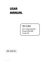
4.3 Name plate
The servo drive features two name plates. A comprehensive name plate can be found on the
right-hand side. An extract showing the main data can be found at the top of the servo drive.
1
Catalog number
6
Output rated voltage
11
Customer-specific
2
Max. ambient temperature
7
Output rated current
12
wye-source only
3
Input rated voltage
8
Output frequency range
13
CE - Conform
4
Input rated current
9
Protection class
14
cULus – Listed
5
Input frequency
10
Serial number
Large
name
plate
Small
name
plate

BECKHOFF Drive Technology 4 Product description
AX5000 Version : 4.5 17
4.4 Technical data
UL-Listing!
It is essential to observe chapter 3.3 if you wish to operate an AX5000 in
USA or Canada.
4.4.1 Permissible ambient and operating conditions
Ambient / operating conditions
Permissible values
Ambient temperature during operation
0 °C to +50 °C
Ambient temperature during transport /
storage
-25 °C to +70 °C
Air humidity
5 % to 95 %, non-condensing
Pollution degree
2 according to EN 60204/EN 50178
Corrosion protection
Normally not required.
Under extreme operating conditions separate
measures must be agreed with the manufacturer.
Operating altitude
up to 1000 m above sea level
Installation position
vertical
Ventilation
Total device current ≤ 3 A: free convection
Total device current > 3 A: built-in temperature-
controlled fan
Protection class
IP 20
Vibration test (EN 60068-2-6)
Frequency range: 10-500 Hz
Amplitude: 10-58 Hz = 0,075 mm pk-pk
59-500 Hz = 1 g
Shock test (EN 60068-2-27)
Half sine wave amplitude: 5 g
Duration: 30 ms
Number of shocks: 3 per axis and direction
(total 18)
Repetitive shock test (EN 60068-2-27)
Half sine wave amplitude: 5 g
Duration: 30 ms
Number of shocks: 1000 per axis and direction
(total 6000)
EMC
Category C3 - standard
Category C2, C1 - auxiliary filter required
4.4.2 Electrical data - single-channel servo drive (AX51xx)
4.4.2.1 Single-phase connection
Electrical data
AX5101
AX5103
AX5106
Rated output current
1.5 A
3 A
4.5 A
Minimum channel current at full current
resolution
0.35 A 1 A 1 A
Max. output current
(1)
4.5 A
7.5 A
13 A
Rated supply voltage
1x 100
-10%
– 240
+10%
V
AC
Max. DC link voltage
890 V
DC
Rated apparent power

4 Product description BECKHOFF Drive Technology
18 Version : 4.5 AX5000
Electrical data
AX5101
AX5103
AX5106
S1 mode (selection)
120 V
230 V
0.3 kVA
0.6 kVA
0.6 kVA
1.2 kVA
1.2 kVA
2.4 kVA
Power dissipation
(2)
35 W
50 W
85 W
Max. continuous braking power
(with internal brake resistor)
50 W 50 W 150 W
Max. braking power
(with internal brake resistor)
14 kW
Min. brake resistor
(external brake resistor)
47 Ω
Max. braking power
(with external brake resistor)
15 kW
(1)
I
eff
for max. 7 s
(2)
S1 mode, including power supply unit, without brake chopper
4.4.2.2 Three-phase connection
Electrical data
AX
5101
5103
5106
5112
5118
5125
5140
Rated output current [A]
1,5
3
6
12
18
25
(1)
40
Minimum channel current [A]
at full current resolution
0,35 1 1 6 8 12 18
Max. output current
(3)
[A]
4,5
7,5
13
26
36
50
80
(4)
Rated supply voltage [V
AC
]
3x 100
-10%
– 480
+10%
(2)
Max. DC link voltage [V
DC
]
890
Rated apparent power [kVA]
S1-mode (selection)
120 V
230 V
400 V
480 V
0,3
0,6
1,0
1,2
0,6
1,2
2,1
2,5
1,2
2,4
4,2
5,0
2,5
4,8
8,3
10,0
3,4
7,2
12,5
15,0
4,8
10,0
17,3
20,8
8,3
16,0
27,7
33,3
Power dissipation
(5)
[W]
35
50
85
160
255
340
510
Max. continuous braking power [W]
(with internal brake resistor)
50 50 150 90 200 200 150
Max. braking power [kW]
(with internal brake resistor)
14 26 26 26
Min. brake resistor [Ω]
(external brake resistor)
47 47 47 30 22 22 22
(4)
Max. braking power [kW]
(external brake resistor)
15 15 15 23,5 32 32 32
(1)
cULus = 24 A
(2)
cULus = AX5118 und AX5125 = 3 x 480 V
AC
± 10%
(3)
I
eff
for max. 7 s
(4)
I
eff
for max. 7 s, if rotating field frequency >3 Hz at max. 40°C
(5)
S1 mode, including power supply unit, without brake chopper
(4)
Brake resistor < 22 Ω –> Please consult our Application Department

BECKHOFF Drive Technology 4 Product description
AX5000 Version : 4.5 19
4.4.3 Electrical data - two-channel servo drive (AX52xx)
4.4.3.1 Single-phase connection
Electrical data
AX5201
AX5203
AX5206
Rated output current / channel
1.5 A
3 A
6 A
Minimum channel current at full current
resolution
0.35 A 1 A 1 A
Maximum rated channel current
3 A
4.5 A
9 A
Total rated output current
3 A
4.5 A
9 A
Max. output current
(1)
/channel
5 A
10 A
13 A
Max. output current
(1)
total device
current
10 A 20 A 26 A
Rated supply voltage
1x 100
-10%
– 240
+10%
V
AC
Max. DC link voltage
890 V
DC
Rated apparent power
S1 mode (selection)
120 V
230 V
0.6 kVA
1.2 kVA
1.2 kVA
2.4 kVA
2.5 kVA
4.8 kVA
Power dissipation
(2)
55 W
85 W
160 W
Max. continuous braking power
(with internal brake resistor)
50 W 150 W 90 W
Max. braking power
(with internal brake resistor)
14 kW
Min. brake resistor
(external brake resistor)
47 Ω
Max. braking power
(with external brake resistor)
15 kW
(1)
I
eff
for max. 7 s
(2)
S1 mode, including power supply unit, without brake chopper
4.4.3.2 Three-phase connection
Electrical data
AX5201
AX5203
AX5206
Rated output current per channel
1.5 A
3 A
6 A
Minimum channel current at full current
resolution
0.35 A 1 A 1 A
Maximum rated channel current
3 A
6 A
9 A
Total rated output current
3 A
6 A
12 A
Max. output current
(1)
/channel
5 A
10 A
13 A
Peak output current
(1)
total device
current
10 A 20 A 26 A
Rated supply voltage
3x 100
-10%
– 480
+10%
V
AC
Max. DC link voltage
890 V
DC
Rated apparent power
S1 mode (selection)
120 V
0.6 kVA
1.2 kVA
2.5 kVA

4 Product description BECKHOFF Drive Technology
20 Version : 4.5 AX5000
Electrical data
AX5201
AX5203
AX5206
230 V
400 V
480 V
1.2 kVA
2.1 kVA
2.5 kVA
2.4 kVA
4.2 kVA
5.0 kVA
4.8 kVA
8.3 kVA
10.0 kVA
Power dissipation
(2)
55 W
85 W
160 W
Max. continuous braking power
(with internal brake resistor)
50 W 150 W 90 W
Max. braking power
(with internal brake resistor)
14 kW
Min. brake resistor
(external brake resistor)
47 Ω
Max. braking power
(with external brake resistor)
15 kW
(1)
I
eff
for max. 7 s
(2)
S1 mode, including power supply unit, without brake chopper
4.4.4 Mechanical data (single-channel servo drive)
Mechanical data
AX
5101
5103
5106
5112
5118
5125
5140
Weight [kg]
ca. 4
ca. 4
ca. 5
ca. 5
ca. 11
ca. 11
ca. 13
Width [mm]
92
185
Height without plugs [mm]
274
Depth without connectors/ [mm]
accessories
232
4.4.5 Mechanical data (two-channel servo drive)
Mechanical data
AX5201
AX5203
AX5206
Weight
approx. 5 kg
approx. 6 kg
approx. 6 kg
Width
92 mm
Height without plugs
274 mm
Depth without connectors / accessories
232 mm
/