Blue Sea Systems PN 7712 User manual
- Category
- Motorcycle Accessories
- Type
- User manual
This manual is also suitable for

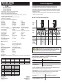
The ML-Series Remote Battery Switch provides high-current carrying and switching under load.
The Remote Battery Switch should be installed close to the battery banks to avoid voltage drop.
Install a single pole double throw (SPDT) or single pole single throw (SPST) control switch in a convenient
location near other electrical controls or companionway to allow quick access in the event of an emergency
(see Illustration on reverse).*
* Although a SPST switch may be used if desired, use of a SPDT switch improves immunity to inadvertent
switching if the controls become damp.
ML- RBS
Remote Battery Switches
PN 7712 / PN 7712B / PN 7712100B
PN 7714 / PN 7714B / PN 7714100B
980010060 Rev.004
• Magnetic Latch (ML) - draws very low current continuous and draws
moderate current for very short time when changing state
• Silver alloy contacts provide high reliability for switching live loads
• Manual override provides LOCK OFF capability for servicing and ON/OFF control with or without power
• LED output to remotely indicate switch state
• Tin-plated copper studs for maximum conductivity and corrosion resistance
• Label recesses for circuit identication
• PNs 7712 and 7714 include a Remote Control Switch PN 2155
Specications 12VDC 24VDC
Cranking Rating See table below See table below
Intermittent Rating See table below See table below
Continuous Rating See table below See table below
ML-Coil Function Auto releasing Auto releasing
Operating Current: Continuous <13mA@ 25°C nominal voltage <13mA @ 25°C nominal voltage
Changing Stage (20 ms) <7A@ 25°C nominal voltage <4A @ 25°C nominal voltage
Contact Circuit Voltage 16V DC Max. 32V DC Max.
Live Current Switching 300A @ 12V DC—10,000 Cycles 150A @ 24V DC—10,000 Cycles
‡
Mechanical Endurance 100,000 Cycles 100,000 Cycles
Control Circuit Voltage 9–16V DC 18–32V DC
Terminal Stud Size 3/8"-16 3/8"-16
Maximum Terminal Stud Torque 140 in-lb (15.8 N•m) 140 in-lb (15.8 N•m)
Ring Terminal Size 3/8" (M10) 3/8" (M10)
Terminal Ring Diameter Clearance 1.18" (30 mm) 1.18" (30 mm)
‡
Predicted performance
RemoteSwitchPN2155
Action SPDT, ON-ON
Seals Internal & External Gasket Panel Seal
Mounting Hole 0.83"x 1.45" (21.08 mm x 36.83 mm)
LED Rating 100,000 hours half-life
HarnessConnector:(selectmodels) Deutsch DTM Series DTM 06-6S
Mating Part Requirements See LADD Industries www.laddinc.com
Receptacle Shell DTM-04-6P
Wedgelock WM-6P
Terminal Pins 1060-20-0122
Sealing Plugs 0413-204-2005
Hand Crimp Tooling DTT-20-0
RegulatoryMeets ISO 8846 and SAE J1171 external ignition protection requirements, CE marked, Rated IP66
Marine Electrical Prod
ucts
PN Termination Control Circuit
Remote Control
Switch Included
7712 Tinned Wires 12V DC SPDT, ON-ON
7712B Tinned Wires 12V DC -
7712100B Deutsch Connector 12V DC -
7714 Tinned Wires 24V DC SPDT, ON-ON
7714B Tinned Wires 24V DC -
7714100B Deutsch Connector 24V DC -
OverviewofApplication
Wire Size (AWG) Metric (mm²) Cranking 10 sec. Cranking 1 min. Intermittent 5 min. Continuous (UL 1107)
2/0 70 2,000A 750A 400A 225A
4/0 120 2,200A 750A 400A 300A
2x (4/0) 2x (120) 2,500A 1,100A 700A 500A
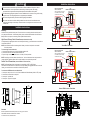
RemoteLEDIndicatorembeddedinPN2155SPDTON-ONConturaSwitch
indicates Remote Battery Switch state or condition as follows:
LED Indication Remote Battery Switch State or Condition
LED is OFF Remote Battery Switch is OFF
LED is ON Remote Battery Switch is ON
LED double blinking ON-OFF
Manual override--check Remote Battery Switch for switch states.
OR Remote Battery Switch mechanical failure
To connect battery bank to load, or combine
battery banks
Set remote switch 2155 to position marked “ON”.
Remote LED indicates closed connection.
To disconnect battery bank from load, or
isolate battery banks that are connected
Set remote switch 2155 to position marked “OFF”.
The remote LED embedded in PN 2155 indicates a closed connection between battery bank and load, or
between two battery banks when used as an emergency cross-connect.
RemoteOperation. PN 2155 (SPDT, ON-ON) Remote Control Contura Switch in the ON position can either
connect the battery bank to the load or combine two battery banks. In the OFF position it can either
disconnect a battery bank from a load or isolate two batteries from each other.
BlueSeaSystemsInc. p360.738.8230
425SequoiaDrive f360.734.4195
Bellingham,WA98226USA [email protected]
www.bluesea.com
Remote
Switch
State
ON OFF
Manual
Control
Knob
Position
Remote Operation Enabled
Remote
Disabled
Remote Operation Enabled
Remote
Disabled
ML-RBS
Relay State
ON
(Closed)
OFF
(Open)
OFF
(Open)
ON
(Closed)
OFF
(Open)
OFF
(Open)
ML-RBS Relay
State will change
to Remote
Switch State
after 10 minutes
-
ON
(Closed)
-
OFF
(Open)
- -
ON
OFF
ML-RBS7712and7714RemoteOperationTable
CAUTION If the ML-RBS Relay state is changed using the Manual Control Knob to a state that is
different than the Remote Switch 2155, the relay state will automatically change to match the Remote Switch
state after 10 minutes. The two scenarios where this will occur are shaded in the table above.

LED
1
2
3
+8
-7
LED
1
2
3
+8
-7
2
AMP MIN.
A
B
START
BATTERY
2155
REMOTE CONTROL SWITCH
SPDT, ON-ON
ENGINE
NOTE: For optional SPST
switch connections
Wire connections are the same
as the SPDT, ON-ON except
the Ground is omitted.
No Connection
orange
green
brown
CONTROL (red)
GROUND (black)
LED OUTPUT (yellow)
+12V DC (red)
1
2
3
6
4
2
AMP MIN.
A
B
START
BATTERY
2155
REMOTE CONTROL SWITCH
SPDT, ON-ON
ENGINE
NOTE: For optional SPST
switch connections
Wire connections are the same
as the SPDT, ON-ON except
the Ground is omitted.
GROUND (black)
LED OUTPUT (yellow)
+12V DC (red)
CONTROL (red)
1.965"
49.91mm
1.010"
25.65mm
.595"
15.10mm
1.125"
28.58mm
TEST CUT
HOLE IN
ACTUAL
CENTER
1.450"
36.83mm
0.830"
21.08mm
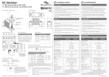
InstallationInstructions
InstallationInstructions
Mounting
Install as close as possible to battery bank. To avoid corrosion to connecting wires and terminals, mount in
a dry and protected location. Avoid mounting directly above vented lead acid batteries so that the Remote
Battery Switch is not exposed to corrosive gasses expelled from the batteries.
HighCurrentPrimaryCircuitConnections (studterminalsAandB)
For help selecting the appropriate wire size and circuit protection rating, go to www.bluesea.com and click the
Circuit Wizard quick link.
NOTE: Stud terminals A and B are interchangeable. A battery connection is required on one terminal
for device operation
Toconnecthighcurrentcircuitwires:
1. Connect the battery bank to one of the stud terminals marked A or B.
2. Connect the load to the other stud terminal marked B or A.
3. Torque the high current terminal stud nuts to 140 in-lbs (15.5 N•m) maximum.
NOTE: If switching an inverter, windlass, bow thruster, etc., the circuit wires must have circuit protection to
comply with ABYC guidelines. Wires used for engine starting do not require circuit protection.
ControlCircuitConnections (wirescontainedinthewireharness)
NOTE: The Remote Battery Switch is designed to be controlled by a SPDT or SPST switch.
Use minimum 16 AWG wire for the Control Circuits. For help selecting the appropriate wire size for the load
cables, go to www.bluesea.com and click the Circuit Wizard quick link.
ToconnecttheSPDTRemoteControlSwitch2155:
1. Connect pin 3 and pin 8 to +12V or +24V Power available when Remote Battery Switch is OFF. (fused)
2. Connect the red control wire to switch pin 2.
3. Connect pin 7 to yellow wire.
4. Connect pin 1 to ground or negative.
4.50"
114.30mm
3.00"
76.20mm
5.47"
138.94mm
3.75"
95.25mm
2.03"
51.56mm
1.90"
48.26mm
1.03"
26.16mm
Guarantee
Blue Sea Systems stands behind its products for as long as you own them.
Find detailed information at www.bluesea.com/about.
For customer service, call 800-222-7617.
These instructions are intended to provide assistance with the installation of this product, and are
not a substitute for a more comprehensive understanding of electrical systems. We strongly
recommend that a competent electrical professional perform the installation of this product.
The illustrated wiring diagram represents a common installation and is not meant to be a guide for wiring
a specic vessel. The wiring diagram shows a single battery bank installation.
Disconnect all negative battery connections before beginning the installation.
All unused control wires should be carefully insulated from each other and from accidental contact
using heat shrink tubing or electrical tape. External contact or shorting between control wires can lead
to malfunction.
CAUTION
TinnedWireTermination
DeutschDTMConnectorTermination
-
 1
1
-
 2
2


Blue Sea Systems PN 7712 User manual
- Category
- Motorcycle Accessories
- Type
- User manual
- This manual is also suitable for
Ask a question and I''ll find the answer in the document
Finding information in a document is now easier with AI
Related papers
-
Blue Sea Systems Automobile Battery Charger PN 7712 User manual
-
-
-
-
Blue Sea Systems 7700 Operating instructions
-
-
-
-
-
Other documents
-
 DIODE LED 12mm Tape Light Terminal Block Connector Installation guide
-
Miele RBS 36 User guide
-
Panasonic AJ8R User manual
-
 tbs electronics DC Modular 500A Remote Battery Switch Installation guide
-
 tbs electronics EN 500A User manual
-
tbs electronics TBS Installation guide
-
 ParkPower 30ARVE25 User manual
-
tbs electronics 48V 350A User manual
-
 SUPER-B TBS Remote Battery Switch Relay User manual
-
SUPER-B TBS to BCI User guide


